Spark and arc protection devices were first developed in the USA and Western countries in the late nineties.
And if their experience already allows them to produce reliable and practical copies, then our manufacturers are still faced with many problems that provoke false alarms of this protection. Among the domestic brands of similar fire-fighting devices, UZM 51MD from the Meander company and UZIS-S1-40 from Ecolight stand out.
Let's take a closer look at each type, with all their pros and cons. Why is such protection needed at all and what our rules and GOSTs say about it, whether it is mandatory for individual buildings and premises, read the article below.
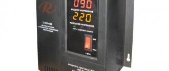
Relay UZM 51MD
First of all, it must be said about this UZM that it is a multifunctional device, and not just protection against sparks and arcs. Until now, another popular product from Meander was widely known - simply UZM-51 M, without the D index.
Simply put, a modular voltage relay that has proven itself on the positive side.
The latest UZM 51MD models, unlike the original ones, which had many complaints, have already begun to provide reasonable protection against dangerous sparking and arc breakdown.
By the way, old models from the manufacturer Meander can also be reflashed and they will get rid of their errors and false positives.
In addition to sparks, this device still protects against both voltage surges and voltage drops below normal. Successfully triggers when the zero is broken and protects equipment.
It also has varistor protection against high-voltage pulse surges in mains voltage.
But don’t place high hopes on it; normal SPDs have not yet been canceled. Without an SPD, it will still be impossible to assemble a full-fledged high-quality electrical panel.
It is quite stupid to rely on the versatility of only one modular protection device.
Scope of application
The use of UZM-51 allows you to prevent failure of electrical equipment during sudden power surges in the network. The device is used mainly in everyday life, installed at the entrance of the power cable to an apartment or individual home. The location of the UZM is not accidental - with this method of placement, it becomes possible to completely shut down the house or part of it in the event of an emergency without stabilizing the voltage.
UZM-51 is an indispensable device for protecting devices and electrical equipment from voltage surges
According to GOST, the voltage in the household electrical network should be 220-230 V with a tolerance of ±10%. That is, a voltage of 207-253 V is considered safe for electricity consumers.
If the voltage diverges from the permissible values, installation of protective devices is required, to which UZM-51 belongs.
The causes of voltage drops are:
- phase distortion, that is, the load on one phase is greater than on the second;
- separation or burnout of “zero” with an increase in voltage to 380V;
- short circuit in one of the lines;
- switching on too much power consumers;
- hitting a power line or directly into a consumer with a powerful lightning discharge.
How it works and where to install
In an emergency, the UZM 51MD device detects an arc, analyzes the parameters of the current passing through it and independently breaks the circuit. It does not require any additional contactor or starter to supply the shutdown pulse.
The rated operating switching current is 63A. Which is more than enough for all apartments and private buildings.
All technical characteristics of UZM 51MD (click '+' to view)
It would seem that on the one hand this is good. However, on the other hand, significant problems with the sensitivity of the protection may arise. Either it will be too sensitive, or, on the contrary, it will not respond to small values.
Setting the settings in such a wide current range is not a trivial task. Catching an arc at Imax=1A is not quite the same as at I=63A.
Why do you think foreign analogues are usually produced with ratings up to 20-25A and less. They have clearly already encountered these problems and have developed a more competent approach.
For example, you don’t install an RCD with a leakage current of 10-30mA at the main input. Otherwise, due to the summation of all interference and “left” interference, there will be constant false shutdowns. It has already become the norm for everyone that such RCDs are installed on separate lines or groups.
Another note about installation on the main input of the distribution board is our winter conditions. Think about what will happen to the boiler room in winter at minus 30 degrees, if in your absence this device catches a glitch and falsely turns off all power supply.
Therefore, the more correct approach here would be the same as with UZOshki. It is wiser to place them on separate groups of lines, rather than on the entire house.
In the West, many TB specialists generally prohibit the installation of such devices on inputs. (link to original)
And if the total load exceeds 63A, can such a protection device be connected via a contactor to increase the switching capacity of the relay? No you can not.
The load current must always pass through the AFDD only. If you put it on the starter coil, then this device will not bring you any benefit.
Main operating parameters
For ease of reference, the technical characteristics of the protective device are given in the table:
| Parameter name | Index |
| Adjustable overvoltage value for disconnecting the consumer, Volt | 243-297 |
| Adjustable voltage drop value for disconnecting the consumer, Volt | 217-163 |
| Permissible voltage difference between phases, % | less than 25 |
| Permissible fluctuations in network frequency, Hz | +5; -5 |
| max current that can be absorbed during a single mains pulse, A | 6500 |
| max current that can be absorbed during repeated network pulses, A | 4500 |
| Rated consumer power, kW | 14,5 |
| Adjustable on timer, | 2s-8min |
| Permissible cross-section of cable cores for terminals, mm² | up to 25 |
| Work mode | around the clock |
| Air humidity at temperature +25°С, % | 80 |
| Weight, kg | no more than 0.45 |
| Work resource, years | 10 |
There are operating conditions, the observance of which will ensure that the device performs its assigned functions:
- the formation of condensation on the product is unacceptable;
- preventing splashes of liquids from entering the housing;
- use at altitudes up to 2 km above sea level;
- the state of the surrounding space is non-aggressive and explosion-proof in terms of gas composition.
Storage of the product in original packaging is allowed at temperatures from -40 to +70°C for 3 years.
It is important to know that UZM-3-63 should not be used in the absence of three-phase equipment. In this case, it is better to install three separate devices, for example UZM-51M, which will prevent de-energization of other consumers in the absence of voltage on one of the phases .
An example of using three single-phase ultrasonic devices installed on each phase
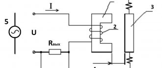
Connection diagram
Three possible connection diagrams for a spark-arc protection device are presented below:
There is nothing complicated here. You simply pass zero and phase through the device. By the way, according to two circuits, the zero generally only needs to be connected to the upper terminal of the device to ensure its operation.
Only a phase will pass through the relay and break inside.
If the accident was short-lived and the network parameters were restored, then after the first operation, the UZM 51MD will automatically turn on the electricity after 30 seconds. Thus, all the food in the refrigerator will be saved from spoilage, the heating pipes will be saved from defrosting, and the fish in the aquarium will be saved from painful death.
If the situation repeats, the device will work again. Just keep in mind that this restart after 30 seconds is a one-time occurrence.
When triggered again, the relay turns off for 4 minutes. And if there was a triple arc detection, further activation can only be done manually by pressing the corresponding button.
By the way, this is a significant contradiction with the rules. According to clause 8.2.2 of GOST 62606, any spark protection device must have a free release mechanism. That is, it turns out that no automatic switching should be provided at all.
The operating instructions for the UZM say something completely different:
This is all connected, of course, with its second function - a voltage relay. Multifunctionality is not always useful, but rather the opposite.
It negatively affects the basic defense and provokes violation of the rules. The device from Ecolight, discussed below, does not provide for any restarts, although it also saves you from overvoltages.
Well-known foreign brands do not have a similar automatic reclosure function.
Operating instructions UZM-51MD - .
Analogs
Analogues of the UZM-51 device include the following devices:
- OM-63 from ;
- RN-106 from NovaTek.
RN-106 is a voltage relay that protects against unauthorized entry into an apartment with a voltage of 380 V. Too high a voltage leads to the failure of all household appliances connected to the network at that moment.
Voltage relay RN-106 prevents failure of home appliances
The OM-63 power limiter is used primarily in single-phase networks. The device immediately turns off the power supply to the home when the power consumption exceeds the established threshold. The device also protects electrical equipment connected to the network from the negative effects of significant voltage drops from nearby lightning strikes or the inclusion of overly powerful equipment.
UZIS S1-40
There is another domestic model of a spark protection device - UZIS S1-40 from the Ecolight company.
First of all, pay attention to the connection diagram. Here the 220V supply voltage must be supplied to the lower terminals, otherwise the device will not work normally.
But for example, in similar “automatic machines” AFDD from ABB ARC1, the connection is freely made both from above and from below. As evidenced by the inscriptions on the case.
Here are 3 diagrams for connecting an AFSD depending on the switching device at the input:
Some are concerned about the question - what will happen if you confuse the connection of phase and zero, because it is not for nothing that the device is marked L and N.
In most cases, the work will be normal, without any comments. But if a parallel phase breakdown occurs on a grounded part of the equipment, an unforeseen situation may arise.
The current that should go through a special sensor will not go through it. His path will run through neutral. As a result, the parameters of the throws will be completely unpredictable for the UZIS, both in shape and in magnitude.
So it is better not to confuse zero with phase when connecting.
Characteristics
The general indicators will be approximately the same for all types of devices. The most important thing is to know what they are needed for and what parameters to pay attention to when choosing a device. All characteristics are reflected in more detail in the technical documentation.
The most significant among them are the following:
- The ability to limit voltage with a current interference of 100A does not exceed 1.2 kV.
- The maximum energy absorption capacity of a single pulse of 10/1000 μs is 200 J.
- Standard impulse protection should operate within 25 ns or less.
- Load cut-off thresholds for exceeding the upper limit are set in the range from 240 to 290 volts.
- The same thing with the upper critical threshold and accelerated load shedding - 300 V plus or minus 15 volts.
- The low voltage shutdown threshold is set in the range from 210 to 100 V.
- The lower critical threshold and accelerated shutdown are set at 80 V plus or minus 10 volts.
- The average power supply indicators for devices are: rated voltage – 230 V, frequency – 50 Hz, maximum voltage – 440 V.
- The electricity supplied to operating devices for their needs is 1.5 Wh, power - 1.5 W.
- Load current (nominal) subject to the use of copper wires with a cross-sectional area of at least 16 mm2 - 63 A.
- Load power (nominal) at a voltage of 250 V – 14.5 kW.
- The maximum load current that the device can withstand for 30 minutes is 80 A.
- The maximum load power in a similar situation is 20 kW.
- The maximum permissible short circuit current is 4500 A.
Switching off short-circuit currents
Another design criticism that worries many experienced electricians is the complete lack of any resemblance to arc chutes.
On the same UZM-51MD it is indicated that its maximum breaking capacity is 4.5 kA.
But here there is nothing. How will this affect the contacts during operation during switching shutdowns and switching ons? Not under normal conditions.
This can be explained primarily by the fact that the ultrasonic protection system should functionally only work in tandem with a circuit breaker or a differential switch, which is responsible for the entire function of short-circuit protection and disconnection of emergency current loads.
At short-circuit currents up to 6 kA, the contacts of the ultrasonic device will be closed and its main task is to “endure” and pass this current through itself without consequences, which it successfully copes with. It is precisely the circuit breaker that should break an arc of such magnitude.
Why does electricity fluctuate?
The main root causes of surges include:
- short circuit of the power and neutral lines, as a result of which the voltage rises to 380 V;
- burnout or breakage of the zero phase at low voltage will increase its performance to 380 V;
- phase imbalance, in which the load is not distributed equally, and most of it moves to 1 phase, which leads to a decrease in voltage.
Return to content
How to check the spark protection device
In addition to the module itself, it comes with a testing and verification device. The so-called spark simulator UZIS-I-002.
How does he work? When it is plugged into a socket, an instant current pulse is released. It has a very steep leading edge.
In real networks there is no such peak. And if the device is really working and there is no interference on the line to dampen the pulse, then the ultrasonic device from this “plug” should work 100% of the time.
When using models from other manufacturers, some consumers artificially want to check the performance of such devices. They risk their health by creating sparks themselves by connecting a phase into a gap through carbon brushes.
Or even directly. Never do this or conduct such experiments.
For ultrasonic devices from Ecolight, just plug the tester into a socket and the device should immediately come out. With its help, you can easily determine the boundaries of the protected circuit.
When the wiring in a large house is too long and branched, then if there is a spark in the farthest outlet, the arc and spark protection device may not work. Why is this possible?
Because the arc current simply will not reach its minimum threshold for triggering.
According to GOST IEC 62606, the minimum permissible arc current for detection and subsequent shutdown is 2.5A in addition to the main load current.
The greater this arc current, the faster the relay will turn off. This does not depend on the load itself.
If your line is idling and sparking has started, then a current of approximately 1.5A is sufficient for an ultrasonic device from Ecolight. It has been experimentally established that if the arc current is less than a certain value (I = 2.5A), then this will not lead to any fire.
And in the UZIS S1-40 this threshold is lowered by almost one and a half times! The same cannot be said about the UZM 51MD. There the minimum operating current is as much as 5A! Apparently to combat false shutdowns.
However, a current of such magnitude is a direct violation of GOST requirements. Keep this in mind.
Principle of operation
It is also important to explain how the UZM-51M works. After turning on the device to the network, there is a time delay before turning on, at this moment the input voltage is measured. If the voltage is within acceptable limits, the green indicator turns on - the device is ready for operation, power is supplied to consumers. Otherwise, the yellow indicator lights up and the load is not connected to the network.
If during operation of the UZM the voltage approaches the upper threshold, the yellow LED begins to flicker, and when it goes beyond it, the load is turned off and the red light comes on. This signals that the set parameters have been exceeded. In the case when the voltage drops to the lower threshold, the green LED begins to flicker, and when it goes beyond the set limits, the red indicator lights up and flickers.
When you press the “Test” button on the device body, the red and green LEDs switch alternately, and the load is disconnected from the network. To return to working condition, you must press the “Test” button again.