Instead of an introduction
I would like to say right away that in this article I will not delve very deeply into the intricacies of programming; it is assumed that the reader has at least the minimum basics. I’ll tell you in general how the resources were used and interesting points. The prerequisites for creating this method arose during the creation of my electric car: Click here! I will say right away that this was created more out of sporting interest than for serious practical work, but nevertheless it works and can be useful to someone.
Writing a sketch
The data that the Bluetooth module receives comes via UART (aka Serial connection) at a speed of 9600 bps. There is no need to configure the Bluetooth module: it is immediately ready for use. Therefore, the sketch should be able to do the following:
Features of sketch filling
To communicate Bluetooth-Bee with the controller, the same pins (0 and 1) are used as for the firmware. Therefore, when programming the controller, the “SERIAL SELECT” switch on the “Wireless Shield” must be set to the “USB” position, and after flashing it must be returned to the “MICRO” position.
What is the entire system based on and how is it implemented in hardware?
The workflow is as follows: we read the file containing the data from the server using a program running on a PC/laptop.
This program sends data to the controller via USB. The controller receives data and performs actions on it. The scheme with a server is attractive because you can manage the scheme without an application, simply by accessing the site from any smartphone/tablet/PC/laptop anywhere in the world where there is access to the Internet. PS. The server part is described below.
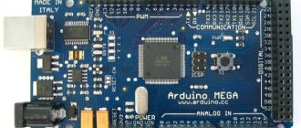
In this article I will control the Arduino MEGA 2560 (Chinese equivalent), but behind the scenes the circuit worked smoothly with the PIC16F877A, the only thing I had to use was a USB-TTL adapter:
Of course, the program for PIC is somewhat different from the program for Arduino, due to different types of MK, but the principle is the same:
We receive data via the COM port, compare it with the internal command table and perform the appropriate action.
The scheme initially seemed very simple to me, but there was one BUT - there was no program that would read a file on the Internet and send the data to the COM port. Accordingly, such a program had to be written.
The program was written in VB6. To read a file from the server, the VB6 component is used: Microsoft Internet Transfer Control 6.0. It simply reads a text file on the server into a string variable. Once read, this string is sent to the COM port using the VB6: Microsoft Comm Control 6.0 component. The entire process of reading a file and sending a string is read in a loop using a timer. The timer interval can be changed in the program config, or directly during operation. In addition, you can select the port operating mode, its number, Internet connection operating mode and a link to the file to be read.
I would like to make a note that with large file sizes and small intervals the program freezes, but continues to work. The buffer size of my program is 512 bytes. Considering that my MK has a smaller buffer, this is enough.
Important point. The program in MK does not know how to parse data, it can only read which character was transmitted to the input via the serial port. Without errors, I was able to accept the Latin alphabet (26 characters AZ and 10 numbers 0-9). A total of 36 commands, if the algorithm is modified and data parsing is introduced into the MK, then any data can be transferred. There is also the possibility of “doping” the software for two-way data exchange.
Arduino IDE
Installation
Download the Arduino IDE development environment from the official website and install the current version for your operating system. In the download window, click JUST DOWNLOAD to start downloading without donating
- to installer 1.8.13 for Windows 7 and higher
- If you have Windows XP, download version 1.6.13
- During installation, the program will ask you to install the driver - we agree to everything
- Installation on Linux from the system repository - read here
- Installation on MacOS – read here
- It is CRITICALLY NOT RECOMMENDED to install the Arduino Windows app from the Windows 10 app store, as well as Beta Builds, Hourly Builds and older versions!
Unpacking the portable
Instead of completely installing the program, you can download an archive with an already “installed” one; on the download page it is called a Windows ZIP file. Here is a direct link to 1.8.13. After unpacking the archive, we get a portable version of the Arduino IDE, which can be transferred to a flash drive and used on any computer without installing the program. But you will need to install the driver for Chinese boards, as well as the drivers from the folder with the Arduino IDE program. You may need to install Java.
IDE update
Before installing a new version, you need to remove the old one. Under no circumstances should you delete the folder of the installed IDE from Program Files; you need to delete it through “Add or Remove Programs”, or by running the uninstall.exe file from the folder with the installed program. Otherwise, the installer will refuse to install the new program, since traces of the old one remain in the system. The solution to this problem is described in the video below. Briefly about how to remove IDE manually:
- Program folder
- C:\Program Files (x86)\Arduino\ (64-bit Windows)
C:\Program Files\Arduino\ (32-bit Windows)
- Documents\Arduino\
- C:\Users (or Users)\Your_user\AppData\Local\Arduino15\
Removing traces from the registry:
- Open the system registry editor:
- Windows 10: Start/regedit
Previous: Start/Run/regedit
- In the search window we write arduino\uninstall
- Search
Problem solving
- If the Arduino IDE stops starting, delete the preferences.txt file from C:\Users (or Users)\Your_user\AppData\Local\Arduino15\
Software
HTML code. Form with 2 buttons, turning on/off the LED on the board: Controlling the LED LED: PHP code, here we write command A to the file if the LED should be on, and B if it should go out: Now the actual code for Arduino: int val; // free up memory in the controller for the variable void setup() { Serial.begin(9600); // connect the serial port pinMode(13, OUTPUT); // declare pin 13 as output } void loop() { // check if any commands are coming if (Serial.available()) { val = Serial.read(); // variable val is equal to the received command if (val == 'a') {digitalWrite(13, HIGH);} // when a turns on the LED if (val == 'b') {digitalWrite(13, LOW);} / / at b turn off the LED }} The program itself for reading information on the server with forwarding to the COM port and its source code are in the archive at the link: Yandex-Disk The program is compiled into several code variants, there may be some differences in operation, but must not be. When you run the EXE for the first time, a help file and a config file are generated. Data from this file is read when the program starts, if it exists. If the file does not exist (for example, when the program is launched for the first time), then the config file is created with default values.
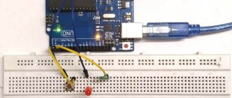
Connection diagram
We connect resistors directly to the RGB pins and Arduino pins. We are using a common anode RGB LED, so the common pin must be connected to 5V. If you are using a common cathode RGB LED, you should connect the common pin (which is longer) to GND (ground) instead.
We'll use digital outputs 3, 4 and 5, but you can use other pins if you want.
Send an example
The following figure shows an example of sending instructions from an Android application. It controls the LED switch via the Bluetooth module, and you can see that the command can be sent not only through the button on the app interface, but also through voice. Specific content will be presented in steps 1, 2 and 3.
Figure 1: Android App Control LED
Rice. 2. Android application interface.
Receiving data from the device
In the code snippet above, notice the line containing serialPort.read(mCallback). Here, the read function is passed a reference to a Callback object, which will automatically fire when incoming data is detected.
UsbSerialInterface.UsbReadCallback mCallback = new UsbSerialInterface.UsbReadCallback() { // Define a callback method that is called when data is received. @Override public void onReceivedData(byte[] arg0) { String data = NULL; try { data = new String(arg0, "UTF-8"); data.concat("/n"); tvAppend(textView, data); } catch (UnsupportedEncodingException e) { e.printStackTrace(); } } };
The received data will be in the form of raw bytes. We will have to re-encode them into a readable format, such as UTF-8. They are then added to the TextView using the special tvAppend() method. This is done this way because any changes to the UI can only be done on the UI thread. Since this Callback will be run as a background thread, it cannot directly affect the user interface.
private void tvAppend(TextView tv, CharSequence text) { final TextView ftv = tv; final CharSequence ftext = text; runOnUiThread(new Runnable() { @Override public void run() { ftv.append(ftext); } }); }
Preparing for work
Most microcontrollers have multiple I/O ports. The UART protocol is the most suitable for communication with a PC. This is a serial asynchronous data transfer protocol. To convert it to a USB interface, there is a USB-RS232 – FT232RL converter on the board. To complete the examples in this article, you will only need an Arduino-compatible board. We use EduBoard. Make sure your board has an LED connected to pin 13 and a reset button.
Virtuino
An Android program designed to monitor the sensor. Controls electrical devices via Bluetooth, Wi-Fi or the Internet.
With the help of Virtuino you can create:
The application is able to combine several projects into one. Controls excellent platforms simultaneously via Bluetooth and Wi-fi. Free to use. Belongs to the System Maintenance subcategory. It is possible to design interior design with different visualizations.
You can learn Virtuino using tutorials and video lessons with library support. For now the application works in English mode.
USB Serial Library
Setting up a serial connection in Android is quite labor intensive as it requires you to manually configure a lot of things, so I found a few libraries that do it all automatically. I tested several of them and finally settled on the UsbSerial library from Github user felHR85. Among similar libraries that I found, it is the only one that is still updated. It's quite easy to set up and use. To add the library to your project, download the latest JAR file from Github. Place it in the libs subdirectory of your project directory. Then, in the file explorer in Android Studio, right-click on the JAR file and select “Add as Library”. That's all!
Creating an application
Select File->New->Project.
Since we are creating an application for android, select Android->Android Application Project, and click Next
The following dialog box:
Application Name -> write the application name, Project Name -> write the project name, Package Name -> We don’t write anything, it is created automatically! Minimum Required SDK -> this is the minimum requirement; we indicate our version of Android; I have 4.1 and that’s what I choose. Target SDK -> select your version of Android Compile with -> select your version of Android Theme: to begin with, I would advise choosing None. Click Next. You don't need to change anything in the next window. Just click Next.
Next, we are offered to create our own icon for the application, you can change the standard shortcut by uploading your picture, but to begin with, I suggest just clicking Next.
Next, select the Blank Activity menu item and click Next.
Click Finish and after a few seconds the main window of our program opens. Select the Activity_main.xml tab and see our editor:
- Our project files.
- Run Launches the emulator to check the program for errors
- Text button panel and much more from here you will select what you need and add as application elements
- To select the display size of your phone or tablet
- Selecting orientation. Two types: horizontal and vertical
- API level (better not to touch)
- Everything that you have added to the application will be displayed here; you can also rename your added elements or delete them.
- Shows the properties of the element, its size, color, etc., you can also edit the element here
- Indicates the presence of errors.
- Select editing (graphic or text). For beginners, of course, it is better to use the graphical mode
- Your application window, you can see the interface of the future application
Now let's add two buttons to the application interface. Select the Button element and move it to the form.
At the top right we see the objects we added. It is also important which of the objects is currently selected. At the bottom right you can edit the button, let's change the button label text and its color. To do this, in the properties field of the “Text” element, enter the value “ON” instead of button1, and “OFF” for button2. It should look like this: We can run the newly created application on the emulator. Go to the launch settings “Run” → Run Configurations”, on the left side click on “Android Application”. A new configuration “New_configuration” appears. On the right side of the window, select the “Target” tab and select the “Launch on all compatible devices/AVD” option and add the device. We check that the buttons have appeared and can be pressed. If everything is good, we continue further. Now in the project files select bin->AndroidManifest.hml
Now click on AndroudManifest.hml from below
We will need to add two lines to this file:
They will ask you to turn on Bluetooth when the application starts; if it is turned off, the application will ask the user to turn it on. You need to add it here:
Next, open another file: src->com.example(name)
This file will contain our main code. All its contents need to be deleted and this code inserted:
package com.example.NAME;//Instead of NAME, enter the name of your project import java.io.IOException; import java.io.OutputStream; import java.util.UUID; import com.example.NAME.R; import android.app.Activity; import android.bluetooth.BluetoothAdapter; import android.bluetooth.BluetoothDevice; import android.bluetooth.BluetoothSocket; import android.content.Intent; import android.os.Bundle; import android.util.Log; import android.view.View; import android.view.View.OnClickListener; import android.widget.Button; import android.widget.Toast; public class MainActivity extends Activity { private static final String TAG = "bluetooth1"; Button button1, button2;//Indicate the id of our buttons private static final int REQUEST_ENABLE_BT = 1; private BluetoothAdapter btAdapter = NULL; private BluetoothSocket btSocket = NULL; private OutputStream outStream = NULL; // SPP UUID of the service private static final UUID MY_UUID = UUID.fromString("00001101-0000-1000-8000-00805F9B34FB"); // MAC address of the Bluetooth module private static String address = "00:00:00:00:00"; //Instead of “00:00” You will need to enter the MAC of our bluetooth /** Called when the activity is first created. */ @Override public void onCreate(Bundle savedInstanceState) { super.onCreate(savedInstanceState); setContentView(R.layout.activity_main); button1 = (Button) findViewById(R.id.button1); //Add the names of our buttons here button2 = (Button) findViewById(R.id.button2); btAdapter = BluetoothAdapter.getDefaultAdapter(); checkBTState(); button1.setOnClickListener(new OnClickListener() //If button 1 is pressed then { public void onClick(View v) { sendData("1"); // Send number 1 via bluetooth Toast.makeText(getBaseContext(), "Turn on LED ", Toast.LENGTH_SHORT).show(); //display a message on the device } }); button2.setOnClickListener(new OnClickListener() { public void onClick(View v) { sendData("0"); // Send number 1 via bluetooth Toast.makeText(getBaseContext(), "Turn off LED", Toast.LENGTH_SHORT).show (); } }); } @Override public void onResume() { super.onResume(); Log.d(TAG, "...onResume - connection attempt..."); // Set up a pointer to the remote node using it's address. BluetoothDevice device = btAdapter.getRemoteDevice(address); // Two things are needed to make a connection: // A MAC address, which we got above. // A Service ID or UUID. In this case we are using the // UUID for SPP. try { btSocket = device.createRfcommSocketToServiceRecord(MY_UUID); } catch (IOException e) { errorExit("Fatal Error", "In onResume() and socket create failed: " + e.getMessage() + "."); } // Discovery is resource intensive. Make sure it isn't going on // when you attempt to connect and pass your message. btAdapter.cancelDiscovery(); // Establish the connection. This will block until it connects. Log.d(TAG, "...Connecting..."); try { btSocket.connect(); Log.d(TAG, “...The connection is established and ready to transmit data...”); } catch (IOException e) { try { btSocket.close(); } catch (IOException e2) { errorExit("Fatal Error", "In onResume() and unable to close socket during connection failure" + e2.getMessage() + "."); } } // Create a data stream so we can talk to server. Log.d(TAG, "...Creating Socket..."); try { outStream = btSocket.getOutputStream(); } catch (IOException e) { errorExit("Fatal Error", "In onResume() and output stream creation failed:" + e.getMessage() + "."); } } @Override public void onPause() { super.onPause(); Log.d(TAG, "...In onPause()..."); if (outStream != NULL) { try { outStream.flush(); } catch (IOException e) { errorExit("Fatal Error", "In onPause() and failed to flush output stream: " + e.getMessage() + "."); } } try { btSocket.close(); } catch (IOException e2) { errorExit("Fatal Error", "In onPause() and failed to close socket." + e2.getMessage() + "."); } } private void checkBTState() { // Check for Bluetooth support and then check to make sure it is turned on // Emulator doesn't support Bluetooth and will return NULL if(btAdapter==NULL) { errorExit("Fatal Error" , "Bluetooth is not supported"); } else { if (btAdapter.isEnabled()) { Log.d(TAG, “...Bluetooth is enabled...”); } else { //Prompt user to turn on Bluetooth Intent enableBtIntent = new Intent(btAdapter.ACTION_REQUEST_ENABLE); startActivityForResult(enableBtIntent, REQUEST_ENABLE_BT); } } } private void errorExit(String title, String message){ Toast.makeText(getBaseContext(), title + » — » + message, Toast.LENGTH_LONG).show(); finish(); } private void sendData(String message) { byte[] msgBuffer = message.getBytes(); Log.d(TAG, "...Sending data: " + message + "..."); try { outStream.write(msgBuffer); } catch (IOException e) { String msg = "In onResume() and an exception occurred during write: " + e.getMessage(); if (address.equals("00:00:00:00:00:00")) msg = msg + ".\n\nYou have 00:00:00:00:00:00 written in the address variable, you need register the real MAC address of the Bluetooth module"; msg = msg + ".\n\nCheck SPP UUID support: " + MY_UUID.toString() + " on the Bluetooth module you are connecting to.\n\n"; errorExit("Fatal Error", msg); } } }
NECESSARILY! Enter instead of 00:00:00:00:00 the MAC of your Bluetooth module, which can be found through the Bluetooth terminal!!! Your application is ready. Now we need to check how it behaves on the device. Run the simulator for this. If it starts normally without errors, then a file with your program will be created in the folder where you created your project. You need to copy it and install it on your device.
Bluetooth Controller 8 Lamp
The Arduino platform was created in 2003. It achieved universal attention thanks to its low price, as well as a multi-million dollar community aimed at in-depth study of programming. Microprocessors and microcontrollers come with boards. Arduino is considered the most popular. Italian models have many functions to expand and explore built-in Pro systems.
Bluetooth Controller 8 Lamp is designed to regulate the functions of Arduino with an 8-channel controller. Works using Bluetooth modules HC-05, HC-06 and HC-07. 8 button interface corresponds to each light bulb.
The method is active only within visibility. Compared to other wireless methods, this is the cheapest. Board components cost less than $1. Even used options are suitable for the job. Static devices, using an infrared controller in ceiling LED strips, easily solve problems that arise during the process.