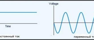
Electrical circuits are characterized by the presence of different types of voltage. Linear voltage (LV) occurs between the phase conductors of a three-phase circuit. All parts (phases) of a multiphase circuit have an identical current characteristic. The name of the circuits (six-, three- or 2-phase) is determined by the number of phases. Three-phase electrical circuits are most widespread, as they are the most economical in comparison with multiphase or 2-phase ones. They also make it possible to obtain LN and phase voltage (PV) on one unit.
Features of Line Voltage
Electrical circuits are characterized by the presence of different types of voltage. Linear voltage (LV) occurs between the phase conductors of a three-phase circuit. All parts (phases) of a multiphase circuit have an identical current characteristic. The name of the circuits (six-, three- or 2-phase) is determined by the number of phases. Three-phase electrical circuits are most widespread, as they are the most economical in comparison with multiphase or 2-phase ones. They also make it possible to obtain LN and phase voltage (PV) on one unit.
Which voltage is called linear and which phase?
Linear is the voltage between 2 phases of a line or when the value between 2 wires of different phases is determined.
The voltage between any phase and zero is phase. It is measured between the initial and final stages of the phase. In practice, FN differs from LN by 58-60 percent. That is, the LN values are 1.73 times greater than the FN values.
Three-phase circuits have 380V LN, which allows you to get 220V phase.
Nuances
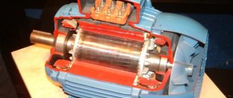
Continuing the conversation about engines, we cannot ignore the issue of choosing a switching circuit. The fact is that usually the engine on its nameplate contains the following markings:
In the first line you see the symbols for a triangle and a star, note that the triangle comes first. Next, 220/380V is the voltage on the delta and star, which means that when connecting with a delta, the line voltage must be equal to 220V. If the voltage in your network is 380, then you need to connect the motor to a star. While phase is always 1.73 less, regardless of the linear value.
An excellent example is the following engine:
Here the rated voltages are already 380/660, which means that for linear 380 it needs to be connected with a triangle, and the star is intended for power supply from three phases of 660V.
If in powerful loads they often operate with interphase voltage values, then in lighting circuits in 99% of cases phase voltage is used (between phase and zero). The exception is electric cranes and the like, where a transformer with secondary windings with linear 220 V can be used. But these are rather subtleties and specifics of specific devices. It’s easier for beginners to remember this: phase voltage is the one in the socket between phase and zero, linear voltage is in the line.
Differences
The specificity of the LN is an indicator by which currents and other quantities of a three-phase circuit are calculated. This scheme allows you to connect single- and three-phase contacts. The nominal value is 380V and changes with changes in a limited network, for example, due to surges.
The most popular is a circuit with a neutral and grounding. Connection in such a system is made according to the following scheme:
- Single-phase wires are connected to phase wires;
- to 3-phase - 3-phase.
The breadth of use of LN is determined by its safety and convenience of chain branching. In this case, the equipment is connected to the phase output, and only this is not safe.
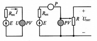
Calculation of the system is simple; standard physical formulas apply. The parameters of the LN network are measured with a multimeter, and the FN parameters are measured with special devices, for example, a voltmeter, a current sensor, or a tester.
- The wiring of such wiring does not require the use of professional equipment. Screwdrivers that have indicators are sufficient.
- The risk of electric shock is very low. This is explained by the free neutral present in the circuit. The connection of conductors does not require connecting the 0th pin.
- The circuit is suitable for all types of current.
Important! A 1-phase circuit can be connected to a 3-phase circuit. The opposite cannot be done.
- This connection scheme is suitable for many devices that require high power to operate. LN allows you to increase engine efficiency by 33%.
When switching the generator windings to a triangle from a star, it causes an increase in the value of LN by 1.73 times.
Important! The difficulty of detecting damage in a linear connection is an important disadvantage of the circuit, since this can result in a fire.
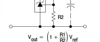
The difference between LN and FN is the difference in the connected winding wires. To control the parameters of LN and FN, you will need a pulse stabilizer, or, in other words, a linear stabilizer. This device makes it possible, while maintaining the indicator at the same level, to normalize the voltage if it has increased sharply. The device can be connected to the contacts of electrical equipment, a regular outlet.
Ratio of phase and line voltage
The ratio between line and phase voltage is 1.73. That is, at one hundred percent of the LN power, the phase voltage will be 58%. That is, LN exceeds FN by 1.73 times and is stable.
The voltage in a three-phase circuit is estimated based on the parameters of the linear component. Usually it is 380 volts and is identical to 220 volts of the phase component of a three-phase electric current network. In electrical networks where there are four wires, the 3-phase voltage is designated 380/220V. This allows you to connect to such a network equipment with 1-phase electricity consumption of 220V and powerful devices that can operate on 380V.
A three-phase circuit with 380/220V 0 wire is universal and acceptable in most cases. Electrical appliances that operate on a single-phase voltage of 220V can, when connected to a pair of FN wires, be powered by the LN.
Electrical equipment that is powered from a three-phase network can only work if there is a connection simultaneously to 3 terminals of different phases. Then grounding is not necessary, but if the insulating material of the wire is damaged, then the absence of 0 significantly increases the risk of electric shock.
Important! As the LN decreases, the FN values change. With the value of the phase-to-phase voltage already determined, it will not be difficult to determine the value of the FN.
What we do in practice
We have figured out how we get two voltages in a three-phase network, now let’s figure out how this is used in practice.
In everyday life, most electrical appliances are powered by single-phase voltage. The voltage in the electrical network is standardized - 230V with a frequency of 50 Hz, and all household appliances are designed to be powered by this voltage. If the device requires a reduced voltage, for example, 5, 12, 19, 36 volts or any other value, then it has either a built-in or remote power supply, which, in fact, generates the required voltage.
When it is necessary to connect powerful devices, for example, electric boilers and stoves, welding equipment, machine tools and other things, a problem arises - high current. For example, a regular socket is designed for a current of up to 16A, which can carry a cable with a conductor cross-section of 2.5 mm² for a long time; through it you can power devices with a power of up to 3.5 kW.
Therefore, powerful devices are often connected via a separate line directly to the circuit breaker or through 32A power sockets. But for such a current you need to use a cable with a cross-section of current-carrying conductors of 6 mm² or more. Moreover, the maximum load in such a line is 7 kW.
When connecting the load to linear voltage, that is, to two wires of the supply network between which there is 380V and the current consumption is the same 32A, the power of the connected load will already be about 12 kW. That is, a cable with the same core cross-section will be able to power an almost 2 times more powerful load. And a three-phase device with the same current of 32A will already have a power of 21 kW.
And keep in mind that to connect it you won’t need to lay power lines with thicker wires, you won’t have to lay power cables with thick conductors from the distribution board, and so on... Whereas in a single-phase circuit, a device with a power of 21 kW will consume a current of about 95A, and for it for power supply you will need to use a cable with 25 mm² conductors versus 6-8 mm² and 32A in a three-phase circuit.
To reduce the supply current, powerful electrical appliances are made three-phase. But a device designed for 380V is not always three-phase. There are single-phase consumers with a rated voltage of 380V, for example, welding transformers such as TSM-250 and others like that.
From the characteristics we see that the supply voltage is 1x380. That is, its primary winding is connected to two phases. It is curious that many people call such transformers “two-phase”, but this is completely wrong. One EMF acts on the primary winding, just like in any other single-phase device.
There is nothing outstanding here, and this voltage of the primary winding was chosen for the same purpose - to reduce the supply current, which will make it possible to wind the winding with a wire of a smaller cross-section and use cables with a smaller cross-section TPG for connecting to the network.
If it were designed for power supply from 220V, then in maximum load mode the current consumption would be 16,000/220 = 72A, and when powered from 380V, the current would be no more than: 16,000/380 = 42A.
Thus, the presence of two voltages in a three-phase network allows you to connect electrical equipment of any power and different configurations. Which certainly increases the flexibility and ease of use of this power system.
What is it measured in?
According to GOST 13109, the voltage standard in the electrical network varies in the range from 198V to 242V (that is, 220V plus or minus 10 percent). If household appliances, lamps often break down or flicker, you will need to measure the voltage in the electrical wiring. A similar check is done with a multimeter or voltmeter. At night, when electrical appliances are used to a minimum, the values obtained will be maximum.
A multimeter measures the voltage in a three-phase network as follows:
- Between working 0 and each of the phases: A-N, B-N, C-N.
- Linear voltages: A-B, A-C, B-C.
There should be six dimensions in total. Sometimes another measurement is made - between the grounding and neutral working conductor: N-PE.
How to measure
You can measure such a system with a multimeter or using physical formulas.
LN is calculated using the Kirchhoff formula: ∑ Ik = 0. Here the current strength is zero in all parts of the electrical circuit, that is, k = 1. Ohm's law is also used: I=U/R. By applying both formulas, you can calculate the parameters of the brand or electrical network.
In a system of several lines, you will need to find the voltage between 0 and phase IL = IF. The IL and IF values are not constant and change with different connection variations. Therefore, the linear parameters are exactly the same as the phase ones.
Phase
In order to obtain phase connection readings, you will need special equipment, for example, a multimeter, voltmeter. In order to measure currents and voltages in three-phase circuits, it is usually enough to know the data of one linear current and one linear current.
FN is measured when the linear sag (falls). The square root of three is taken from linear quantities. The resulting indicator is the parameters of the physical function.
What are the main differences between linear and phase voltage?
One type of system with multiple phases is represented by circuits consisting of three phases. They operate with electromotive forces of a sinusoidal type, arising at a synchronous frequency, from a single energy generator, and have a difference in phase.
By phase we mean independent blocks of a system with multiple phases, having current parameters identical to each other. Therefore, in the electrical field, the definition of phase has a double interpretation.
Firstly, as a value that has a sinusoidal oscillation, and secondly, as an independent element in an electrical network with many phases. In accordance with their quantity, a specific circuit is marked: two-phase, three-phase, six-phase, etc.
Today in the electric power industry, the most popular are circuits with three-phase current. They have a whole list of advantages that distinguish them from their single-phase and multiphase analogues, since, firstly, they are cheaper in terms of technology for installing and transporting electricity with minimal losses and costs.
Secondly, they tend to easily form a magnetic field moving in a circle, which is the driving force for asynchronous motors, which are used not only in enterprises, but also in everyday life, for example, in the lifting mechanism of high-rise elevators, etc.
Electric circuits with three phases allow you to simultaneously use two types of voltage from one source of electricity - linear and phase.
Types of voltage
Knowledge of their features and operating characteristics is extremely necessary for manipulations in electrical panels and when working with devices powered by 380 volts:
- Linear. It is designated as interphase current, that is, passing between a pair of contacts or identical marks of different phases. It is determined by the potential difference of a pair of phase contacts.
- Phase. It appears when the initial and final terminals of a phase are short-circuited. Also, it is designated as the current that occurs when one of the phase contacts with the zero terminal is closed. Its value is determined by the absolute value of the difference between the leads from the phase and the Earth.
Differences
In an ordinary apartment or private house, as a rule, there is only a single-phase type of network 220 volts , therefore, basically two wires are connected to their power supply panel - phase and zero, less often a third is added to them - grounding.
High-rise apartment buildings with offices, hotels or shopping centers are supplied with 4 or 5 power cables at once, providing three phases of a 380 volt network.
Why such a strict division? The fact is that three-phase voltage, firstly, is itself characterized by increased power, and secondly, it is specifically suitable for powering special heavy-duty three-phase electric motors, which are used in factories, in electric elevator winches, escalator lifts, etc.
When connected to a three-phase network, such motors produce many times more force than their single-phase counterparts of the same dimensions and weight.
When connecting conductors, you do not need to mount a zero contact , because the probability of breakdown is very low, thanks to the unoccupied neutral.
But such a network diagram also has its weak point, since in a linear installation diagram it is extremely difficult to find the location of conductor damage in the event of an accident or breakdown, which can increase the risk of a fire.
Thus, the main difference between the phase and linear types is the different wiring diagrams for connecting the windings of the source and consumer of electricity.
Determining the phase with an indicator screwdriver
The simplest method for determining the phase, which is suitable for any layman, is to use an indicator screwdriver, or as it is also called a “control”.
The control screwdriver is very similar in appearance to a regular one, with the exception of its internal filling. I do not recommend using the blade of a screwdriver to loosen or screw in screws. This is what most often leads to its failure.
How to determine phase and zero with this screwdriver? Everything is very simple:
- ⚡touch the contact with the tip of the screwdriver
- ⚡press or touch the metal button on the top of the screwdriver with your finger
- ⚡if the LED inside the screwdriver lights up, this is a phase conductor; if not, it is a zero conductor
Do not confuse an indicator screwdriver with a dial screwdriver. The latter has batteries in its design. Here , in order to determine the phase and zero, when the tip touches the contacts, you do not need to touch the metal pad at the end with your finger. Otherwise, the screwdriver will glow anyway.
According to the rules, an indicator light designed for 220-380V should glow at a voltage of 50V or more.
The phase in a socket, switch and any other equipment is determined in a similar way.
Safety precautions when working with the “probe”
- ⚡never touch the bottom of the screwdriver when measuring
- ⚡the screwdriver must be clean before measuring, otherwise an insulation breakdown may occur
- ⚡if you need to use an indicator screwdriver to determine the absence of voltage, rather than its presence, in order to safely work with the wiring, first check the functionality of the device on equipment that is known to be energized .
Ratio
The phase voltage value is equal to about 58% of the power of the linear analogue . That is, under normal operating parameters, the linear value is stable and exceeds the phase value by 1.73 times.
The assessment of voltage in a three-phase electric current network is mainly carried out based on the indicators of its linear component. For current lines of this type supplied from substations, it is usually equal to 380 volts, and is identical to the phase analogue of 220 V.
In electrical networks with four wires, the three-phase current voltage is marked with both values - 380/220 V. This makes it possible to power devices from such a network, both with single-phase electricity consumption of 220 volts, and more powerful units designed for a current of 380 V.
The most accessible and universal system has become a three-phase type 380/220 V system , which has a neutral wire, the so-called grounding. Electrical units operating on a single phase of 220 V can be powered from line voltage when connected to any pair of phase terminals.
In this case, the use of the neutral terminal as grounding is not necessary, although in the event of damage to the wire insulation, its absence seriously increases the likelihood of an electric shock.
Why is there 220 volts on one phase and 380 volts on three phases?
Why 3 phases of 220 volts turns out to be 380 volts.
There are 220 volts on one phase, and 380 volts on three phases, because the phase vectors are directed at an angle of 120 degrees to each other. Because of this, in this case it is not arithmetic addition that works, but geometric addition. This is how it is explained.
The 3-phase electrical voltage, which is indicated by R – S – T in the picture below, will show 380 volts when measured with a voltmeter. But, if each phase shows 220 volts, why is this happening?
Everything is very simple. 380 volts, 3 phases, R – S – T form phase angles of 120 degrees each, see picture:
Any of these angles looks like a triangle
We use the triangle rule: the sum of the angles in a triangle is 180 °, the resulting angle RTN and TRN, respectively (180 ° -120 °) / 2 = 30 degrees.
Thus, it turns out that the voltage of 3 phases is 380 volts, while one phase is 220.
They confused a man's head with some triangles, degrees and drawings. There are no geometric figures in the current, this is an ABSTRACT.
And such a difference between the phases occurs due to the fact that between the voltage supply in each of the three phases there is a time difference of a third of the cycle.
For example, to simplify, let’s imagine that the frequency of our network is 1 Hertz (= 1 generator revolution per second).
After starting a three-phase generator, in the first phase the maximum voltage surge will occur in the 0th millisecond, in the second phase in the 333rd millisecond, in the third phase in the 666th.
Then a new cycle begins, in the first phase the shock increases to the 1000th, in the second to 1333, in the third to 1666 and so on.
So, while in the first phase the current excited its maximum of 220 by the 2000th second, the second phase had not yet had time to do this and was excited only by minus 160, respectively, the difference between them is 220-(-160) = 380.
Scheme
Three-phase current units have two connection schemes to the network: the first is “star”, the second is “triangle”. In the first option, the initial contacts of all three windings of the generator are closed together in a parallel circuit, which, as in the case of conventional alkaline batteries, will not increase power.
The second, serial circuit for connecting the windings of the current source, where each initial terminal is connected to the final contact of the previous winding, gives a threefold increase in voltage due to the effect of summing the voltages when connected in series.
Calculation of linear and phase voltage
Networks with linear current have found wide application due to their characteristics of lower risk of injury and ease of wiring such wiring. All electrical devices in this case are connected to only one phase wire, through which the current flows, and only one is dangerous, and the second is the ground.
It is not difficult to calculate such a system; you can be guided by the usual formulas from a school physics course. In addition, to measure this network parameter, it is enough to use a conventional multimeter, while to take readings of a phase-type connection, you will have to use an entire system of equipment.
To calculate the line current voltage, use the Kirchhoff formula:
The equation of which states that for each part of the electrical circuit, the current strength is zero – k=1.
And Ohm's law:
Using them, you can easily calculate each characteristic of a particular brand or electrical network.
If the system is divided into several lines, it may be necessary to calculate the voltage between phase and zero:
These values are variable and change with different connection options. Therefore, the linear characteristics are identical to the phase ones.
However, in some cases, it is necessary to calculate what the ratio of phase and linear conductor is.
To do this, use the formula:
Ul – linear, Uph – phase. The formula is valid only if – IL = IF.
When adding additional outlet elements to the electrical system, it is necessary to calculate the phase voltage individually for them. In this case, the Uph value is replaced with digital data of the independent stamp.
When connecting industrial systems to the power grid, it may be necessary to calculate the value of three-phase reactive power, which is calculated using the following formula:
Identical structure of the active power formula:
Calculation examples:
For example, the coils of a three-phase current source are connected in a star configuration, their electromotive force is 220V. It is necessary to calculate the line voltage in the circuit.
The line voltages in this connection will be the same and are defined as:
Testing the two-phase model
The stator and many other structural elements of a two-phase electric motor have their own distinctive features, which determine the features of the test. The features of checking a two-phase electric motor include the following points:
- In this case, the resistance on the housing must be checked. A reading that is too low indicates that the stator needs to be rewinded.
- To obtain more accurate readings, it is recommended to use a megohmmeter, but such a measuring tool is extremely rare at home.
Before testing an electric motor, a visual inspection should be performed. Mechanical damage can lead to serious performance problems.
How does three-phase voltage differ from single-phase
Three phase = line voltage 380 Volts, Single phase = phase voltage 220 Volts
The article is addressed to novice electricians. I, too, was once a beginner, and I am always happy to share knowledge and raise the professional level of my readers.
So, why do some electrical panels receive a voltage of 380 V, and some - 220? Why do some consumers have three-phase voltage, while others have single-phase? There was a time when I asked myself these questions and looked for answers to them. Now I’ll tell you in a popular way, without the formulas and diagrams that textbooks abound.
Very briefly, for those who will not read further: the voltage of 380 V is called linear and operates in a three-phase network between any of the three phases. The 220 V voltage is called phase and operates between any of the three phases and neutral (zero).
In other words. If one phase approaches the consumer, then the consumer is called single-phase, and its supply voltage will be 220 V (phase). If they talk about three-phase voltage, then we are always talking about a voltage of 380 V (linear). Who cares? More details below.
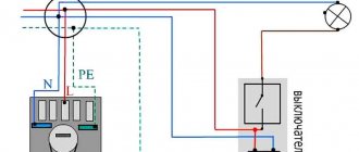
The use of three-phase lines in apartment buildings
Not everyone knows that apartment buildings are also supplied with 380 V. This is what allows shops and various workshops to operate on the first or ground floors. In access switchboards, the three-phase circuit is distributed apartment by apartment, with the result that each of them has one phase and zero. It is they who provide the phase voltage of 220 V.
PHOTO: This is how a three-phase network is divided into three single-phase ones
If it is necessary to connect equipment in the apartment that requires a voltage of 380 V, the owner can submit an application to the management company. The specialist will determine the possibility of such a connection, after which it will be possible to install a three-phase line into the apartment, after first replacing the electricity meter with an appropriate one.
PHOTO: A three-phase electricity meter is much larger than a single-phase one
How are three phases different from one?
In both types of power there is a working neutral conductor (ZERO). I talked in detail about protective grounding here; it is a broad topic. In relation to zero in all three phases - the voltage is 220 Volts. But in relation to these three phases to each other, they have 380 Volts.
Voltages in a three-phase system
This happens because the voltages (with active load, and current) on the three phase wires differ by a third of the cycle, i.e. at 120°.
You can read more in the electrical engineering textbook - about voltage and current in a three-phase network, and also see vector diagrams.
It turns out that if we have three-phase voltage, then we have three phase voltages of 220 V each. And single-phase consumers (and there are almost 100% of them in our homes) can be connected to any phase and zero. You just need to do this in such a way that the consumption in each phase is approximately the same, otherwise phase imbalance is possible.
Read more about phase imbalance and what causes it - here.
And it is best to protect yourself from phase imbalance using a voltage relay, for example Barrier or FiF EuroAutomatika.
In addition, it will be difficult for the overly loaded phase and it will be offensive that others are “resting”)
How to determine zero and phase without instruments
According to the PUE (Electrical Installation Rules), each wire that has its own functional purpose has its own specific color marking:
- the phase wire has insulation in black, white, brown (the most commonly used) colors and their many shades;
- the neutral wire has blue insulation with any shades of it;
- the earth is insulated with yellow-green stripes.
If the regulations were strictly observed, then there would be no problems with determining where the phase is, where the zero is, and where the ground is. In order to make it easier to navigate switching diagrams, phase, zero and ground designations are introduced on many electrical devices. All conductors are designated in accordance with state standards:
- L - this Latin letter designates the phase;
- N - this sign is used to find the neutral wire;
- PE - this combination of letters has always denoted land.
However, the visual method has some subjectivity; it is not always possible to accurately determine the correct color of the conductor insulation. In addition, not all electricians adhere to regulatory documents when carrying out electrical installation work. In old buildings, there is no need to talk about any standards for color marking of wiring.
Therefore, this method of finding phase and zero without instruments exists with a high degree of conditionality; it does not have a 100% guarantee. However, it is the only real way among others, such as using raw potatoes, to determine phase and zero without instruments. To obtain a reliable result, it is better to use data on the compliance of the wires with phase, neutral or grounding, tested using an indicator screwdriver or a multimeter.
Advantages and disadvantages
Both power systems have their pros and cons, which change places or become insignificant when the power passes the 10 kW threshold. I'll try to list.
Single-phase network 220 V, advantages
- Simplicity
- Cheapness
- Below dangerous voltage
Single-phase network 220 V, cons
- Limited consumer power
Three-phase network 380 V, advantages
- Power is limited only by wire cross-section
- Savings with three-phase consumption
- Power supply for industrial equipment
- Possibility of switching a single-phase load to a “good” phase in case of deterioration in quality or power failure
Three-phase network 380 V, cons
- More expensive equipment
- More dangerous voltage
- Limits the maximum power of single-phase loads
Conclusion
Using the capabilities of a three-phase circuit (four-wire circuit), connections can be made in different ways, which makes it possible for its wide application. Experts consider three-phase voltage for connection to be a universal option, since it makes it possible to connect high-power loads, residential premises, and office buildings.
In apartment buildings, the main consumers are household appliances designed for a 220 V network; for this reason, it is important to distribute the load evenly between the phases of the circuit; this is achieved by connecting apartments to the network according to the checkerboard principle. The distribution of the load of private houses differs; in them it is carried out according to the load values on each phase of all household equipment, and the currents in the conductors passing during the period of maximum switching on of the devices.
Source: domelectrik.ru
What's new in the VK SamElectric.ru group?
Subscribe and read the article further:
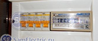
And at the input (in front of the counter) there are approximately the following “boxes”:
Three-phase input. Introductory machine in front of the counter.
A significant disadvantage of a three-phase input (noted above) is the limitation on the power of single-phase loads. For example, the allocated power of three-phase voltage is 15 kW. This means that for each phase - a maximum of 5 kW. This means that the maximum current in each phase is no more than 22 A (practically 25). And you have to spin, distributing the load.
I hope it is now clear what three-phase voltage 380 V and single-phase voltage 220 V are?
Why is it necessary to check the phase voltage before turning it on?
When connecting equipment that requires a voltage of 380 V (for example, an asynchronous electric motor), you should check the voltage on each of the three phases and compare the indicators. This is especially true in private sectors where the voltage is unstable or electricians are insufficiently qualified. The fact is that in villages they often do not pay attention to load distribution. As a result of such actions, one of the phases may be overloaded with minimal load on the others. Coupled with outdated transformers, this leads to phase imbalance. It turns out that in one of the phases the voltage decreases significantly. This leads to overheating of three-phase motors or other equipment and its failure.
Star and Delta circuits in a three-phase network
There are various variations for connecting a load with an operating voltage of 220 and 380 Volts to a three-phase network. These patterns are called “Star” and “Triangle”.
When the load is designed for a voltage of 220V, it is connected to a three-phase network according to the “Star” circuit , that is, to phase voltage. In this case, all load groups are distributed so that the powers in the phases are approximately equal. The zeros of all groups are connected together and connected to the neutral wire of the three-phase input.
All our apartments and houses with single-phase input are connected to Zvezda; another example is the connection of heating elements in powerful heaters and convection ovens.
When the load has a voltage of 380V, it is switched on according to the “Triangle” circuit, that is, to linear voltage. This phase distribution is most typical for electric motors and other loads where all three parts of the load belong to a single device.
What is three-phase current
This is a system that combines three electrical circuits with currents that differ in phase by 1/3 of a period. Moreover, their own EMFs coincide in frequency and amplitude and have the same phase shift. For such a structure, the phase and line voltages are respectively 220 V and 380 V. The frequency of periodic oscillations is 50 hertz (Hz).
If you connect current sinusoidal signals from a three-phase network to an oscilloscope, you will see that they pass through their maximum points in a regular phase sequence.
The general formula for AC power is:
P = I*U*cosϕ,
Where:
- P – power, (W);
- I – current, (A);
- U – voltage, (V);
- cosϕ – power factor.
The cosϕ value should tend to unity. The average power factor lies in the range of 0.7-0.8. The higher it is, the greater the efficiency of the installation.
In the case of 3-phase networks, the power will depend on the connection diagram of the source and load.
Three-phase current graph