5 common questions asked by beginning radio mechanics; 5 best transistors for regulators, circuit composition test
An electrical voltage regulator is needed so that the voltage can be stabilized. It ensures reliable operation and longevity of the device.
The regulator consists of several mechanisms.
TEST:
The answers to these questions will allow you to find out the composition of the 12 volt voltage regulator circuit and its assembly.
- What resistance should the variable resistor have?
a) 10 kOhm
b) 500 kOhm
- How should the wires be connected?
a) Terminals 1 and 2 – power, 3 and 4 – load
b) Terminals 1 and 3 – load, 2 and 4 – power
- Do I need to install a radiator?
a) Yes
b) No
- The transistor must be
a) KT 815
b) Any
Answers:
Option 1. The resistor resistance is 10 kOhm - this is the standard for installing the regulator, the wires in the circuit are connected according to the principle: 1 and 2 terminals for power, 3 and 4 for load - the current will be distributed correctly to the required poles, a radiator must be installed - to protect against overheating, The transistor used is KT 815 - this will always do. In this embodiment, the constructed circuit will work, the regulator will begin to work.
Option 2. Resistance 500 kOhm - too high, the smoothness of the sound in operation will be disrupted, or it may not work at all, terminals 1 and 3 are the load, 2 and 4 are power, a radiator is needed, in the circuit where there was a minus there will be a plus, any transistor - You can really use whatever you want. The regulator will not work because the circuit is assembled incorrectly.
Option 3. Resistance 10 kOhm, wires - 1 and 2 for load, 3 and 4 for power, resistor has a resistance of 2 kOhm, transistor KT 815. The device will not be able to work, since it will overheat greatly without a radiator.
What is a 220V voltage regulator
The abbreviated name of the device in question is RN 0-220 V. The simplest device of this type is a dimmer for incandescent lamps.
The device regulates the parameters of the mains voltage, increases / decreases the degree of the output signal in the range according to the value of the potential difference at its output. Maintains the specified voltage in the consumer circuit. The device regulates (smoothly or gradually) the voltage itself, on which the power in the power range of the connected unit also depends. Works with both reactive and resistive loads, you just need to check whether a particular assembly is suitable, especially for the latter. In addition, it is always necessary to compare the operating power (W) for which the circuit is designed.
PH changes, in accordance with user settings, the level of the output signal from the 220 V network supplied to the load connected to it. Thus, a suitable parameter is set to power a particular device and, more often, to regulate its operation (reducing / increasing the speed of low-power electric motors, light brightness).
The voltage regulator is used:
- in all cases, if a certain voltage, for example 12 V, must be created in the circuit.
- change the rotation speed of small motors of household appliances (the speed of a blender, hair dryer), less often, since not all circuits are suitable, to more powerful motors (for example, drills);
- for other devices whose operation can be configured. And more often (and this is the most correct and effective use) of the lighting level (dimmer), sound volume, heating of heating elements, soldering iron,
Most often, household 0-220 V RNs are used to gradually turn on/off devices.
Factory models usually also have a voltage stabilization chip during power surges, ensuring the devices operate in any mode. According to British standards, a thyristor regulator is called a voltage controller. PH is equipped with universal power supplies on which the voltage can be adjusted.
Types, principle of operation, characteristics
The RN on our topic is intended only for alternating voltage, that is, for a regular 220 V home network.
Most often they are assembled based on the following details:
- transistor.
- thyristors;
- triac;
The circuits also contain capacitors, fixed resistors, and tuning resistors. The selectors of the latter are adjusted. Complex assemblies may include microcircuits.
PH is most effective for resistive loads (resistive, ohmic), meaning they are part of the connected/disconnected user's energy consumption. This is the resistance to the flow of current, such as in the form of a resistor, at the point where electricity is converted into heat.
Resistive loads are heating elements, heating elements, incandescent lamps (not “rulers”).
In an inductive load, the current (much lower than the resistive load) lags behind the voltage and creates reactive power. These are asynchronous electric motors, electromagnets, inductors, transformers, rectifiers. Launch vehicles will not work with them, or will work but ineffectively, creating the risk of equipment failure. There voltage regulators are not always practical.
The thyristor device cannot be used with LED (economical) and fluorescent lamps. Capacitor regulators do not allow smooth voltage fluctuations.
DC motor speed controller using 2 14 volt capacitors.
The practicality of such motors has been proven; they are used in mechanical toys, fans, etc. They have low current consumption, so voltage stabilization is required. Often there is a need to adjust the rotation speed or change the speed of the engine to adjust the fulfillment of the goal presented to any type of electric motor of any model.
This task will be performed by a voltage regulator that is compatible with any type of power supply.
To do this, you need to change the output voltage, which does not require a large load current.
Required parts:
- 2 Capacitors
- 2 variable resistors
Connecting the parts:
- We connect the capacitors to the regulator itself.
- The first resistor is connected to the negative of the regulator, the second to ground.
Now change the engine speed of the device according to the user’s wishes.
The 14 volt voltage regulator is ready.
Simple 12 volt voltage regulator
DIY thyristor charger
There are many electronic circuits, including complex ones, with a full range of adjustments and protection, a significant number of parts, often not cheap. But most car enthusiasts prefer simple thyristor chargers, made from several inexpensive components, which can often be extracted from used equipment, such as a computer.
Selection of the scheme and principle of its operation
First, it is worth noting the main advantage of the proposed thyristor charger circuit: availability and low financial costs. There are other advantages when using the inexpensive thyristor KU202 as the main component:
- Good charging current up to 10 A.
- The energy output is pulse type, which extends the service life of the charged battery.
- For assembly you will need widely available inexpensive parts that are not difficult to find.
- The circuit of a thyristor charger for a car battery can be easily repeated even by a car enthusiast with little knowledge of radio engineering, and an experienced electronics engineer will need no more than an hour to put the device into operation.
According to the principle of operation, this is a phase-pulse power regulator made on a thyristor and allows you to change the current strength. The control electrode KU202 is powered by a transistor circuit. To protect the thyristor charger circuit for a car battery from current surges, a diode VD2 is used. Resistance R5 affects the charging current, the value of which, as is known, is 1/1 of the battery capacity. To power the circuit, you will need a transformer that reduces the mains U = 220 V to 18–22 V. If you have a transformer with a high output voltage at your disposal, the resistance R7 needs to be increased to approximately 2 kOhm (you may have to select a resistor). The rectifier bridge diodes and thyristor must be installed on aluminum radiators to prevent overheating of the parts. When installing conventional elements of type D242–245, do not forget to place an insulating washer under the body.
The schematic diagram of a thyristor charger for a car battery is as follows:
Since the circuit is simple, it does not have electronic protection: its role is played by a fuse installed at the output. When charging batteries with a capacity of no more than 60 A*h, a fuse-link with a rating of 6.3 A is sufficient. Installing a series-connected device - an ammeter - will help control the charging procedure. Below is a printed circuit board that simplifies the assembly of the charger:
List of components in the circuit and selection of possible analogues
The circuit uses an electrolytic capacitor that can withstand a voltage of at least 63 V. The power of resistors R1-R6 is 0.25 W, R7 is 2 W. The diodes in the rectifier bridge pass a current of up to 10 A and maintain a reverse U of 50 V. The pulse diode VD2 must withstand the same voltage. Transistors VT1 and VT2: KT3107, KT502, KT361 and KT503, KT315, KT3102, respectively.
Calculation of transformer, thyristor and diode parameters
One of the negative aspects of thyristor charging is low efficiency, partly due to the secondary winding of the transformer, which must freely pass a current three times greater than the power consumed by the battery. How to fix it? To do this, you can move the thyristor from winding II of the transformer to winding I, as shown in the diagram of a thyristor battery charger:
The whole difference of this thyristor charger for car batteries lies in the connection of the diode bridge and the regulating thyristor to the primary winding of the transformer. Since winding current II is approximately 10 times less than the charging current, very little thermal energy is released on the diodes and thyristor: you don’t even need to use cooling radiators (but this does not apply to VD5-VD8).
Components and their analogues:
- rectifier unit KTs402.405 with any index (A, B, C);
- Zener diode type KS524, KS518, KS522;
- transistor KT117 with letters from “B” to “G”;
- the diode bridge located at the output must consist of components rated at 10 A (D242-247).
Power regulator on triac BTA 12-600
A triac is a semiconductor device, classified as a type of thyristor and used for current switching purposes. It operates on alternating voltage, unlike a dinistor and a conventional thyristor. The entire power of the device depends on its parameter.
Answer to the question. If the circuit were assembled using a thyristor, a diode or diode bridge would be needed.
For convenience, the circuit can be assembled on a printed circuit board.
The plus of the capacitor must be soldered to the control electrode of the triac, it is located on the right. Solder the minus to the third outer pin, which is on the left.
Solder a resistor with a nominal resistance of 12 kOhm to the control electrode of the triac. A substring resistor must be connected to this resistor. The remaining pin must be soldered to the central leg of the triac.
To the minus of the capacitor, which is soldered to the third terminal of the triac, you must attach the minus from the rectifier bridge.
Plus the rectifier bridge to the central terminal of the triac and to the part to which the triac is attached to the radiator.
We solder 1 contact from the cord with a plug to the required device. A 2 contact to the AC voltage input on the rectifier bridge.
It remains to solder the remaining contact of the device to the last contact of the rectifier bridge.
The circuit is being tested.
We connect the circuit to the network. Using a trimmer resistor, the power of the device is adjusted.
The power can be developed up to 12 volts for a car.
Speed controller circuit for an electric motor
To assemble a speed controller for an engine, you will need a PWM pulse generator and a triac to control the engine. The diode and resistor D1 and R1 allow you to reduce the voltage to power the motor, and the capacitor C1 is designed to filter the current at the input of the electrical circuit.
Elements P1, R5 and R3 are voltage dividers with the ability to adjust its values. Resistor R2, which is indicated on the diagram of the electric motor speed regulator, allows you to synchronize the internal blocks of the regulator with the main triac (VT139), on which the speed regulator actually operates.
Below in the figure you can see a visual arrangement of all elements of the speed controller for electric motors. It is imperative to place the elements safely, since the regulator operates from a dangerous voltage of 220 Volts.
Symptoms of a problem
So, in case of low voltage, the battery simply will not charge. That is, in the morning you will not be able to start the car, the lights on the dashboard may not even light up, or troubles will arise while driving. For example, dim headlights at night, unstable operation of the electrical system (problems with electrical appliances - wipers, heaters, radio, etc.).
In case of increased voltage, there is a high probability of a decrease in the electrolyte level in the battery banks, or its boiling. A white coating may also appear on the battery case. When overcharging, the battery may behave inappropriately.
Signs, malfunctions, repair of generator and voltage regulator
In addition, you can also identify the following signs of a faulty voltage regulator (in some cases, some of them may or may not be present, it all depends on the specific situation):
- the control light on the dashboard (although this may be a sign of other malfunctions, for example, that it has burned out, the contact has fallen out, and so on);
- after starting, the battery indicator on the dashboard does not go out, that is, there are obvious malfunctions in charging the battery;
- the brightness of the headlights becomes dependent on the engine speed (you can check this somewhere in a deserted place by placing the car against a wall and accelerating - if the glow changes, then most likely the voltage regulator is faulty);
- the car stopped starting normally the first time;
- constantly discharged quickly ;
- when the engine speed exceeds 2000 rpm, the indicators on the dashboard turn off ;
- the dynamic characteristics of the car decrease , this is especially noticeable at high engine speeds;
- In some cases, the battery may boil .
How to make a current stabilizer for LEDs yourself
Making a stabilizer for LEDs with your own hands is carried out in several ways. It is advisable for a beginner to work with simple circuits.
Driver based
You will need to choose a chip that is difficult to burn out - LM317. It will act as a stabilizer. The second element is a variable resistor with a resistance of 0.5 kOhm with three terminals and an adjustment knob.
Assembly is carried out according to the following algorithm:
- Solder the conductors to the middle and extreme terminals of the resistor.
- Set the multimeter to resistance mode.
- Measure the parameters of the resistor - they should be equal to 500 Ohms.
- Check connections for integrity and assemble the circuit.
The output will be a module with a power of 1.5 A. To increase the current to 10 A, you can add a field switch.
Stabilizer for car lighting
Stabilizer L7812
To operate, you will need a linear device in the form of an L7812 microcircuit, two terminals, a 100n capacitor (1-2 pcs.), textolite material and a heat-shrinkable tube. Manufacturing is carried out step by step:
- Selecting a circuit for L7805 from the datasheet.
- Cut out the required size piece from the PCB.
- Mark the paths by making notches with a screwdriver.
- Solder the elements so that the input is on the left and the output is on the right.
- Make a housing from a thermal tube.
The stabilizing device can withstand up to 1.5 A load and is mounted on a radiator.
Let's take a look inside your potentiometer
The first thing I want to do is introduce you to how a potentiometer works. This means you have to open it up, which is why your list of parts needed included purchasing two potentiometers, just in case you couldn't put the first one back together.
Most potentiometers are held in place by small metal tabs when assembled. You can probably hook these tabs with your side cutters (wire cutters) or pliers, and then bend them up and slightly to the sides. If you do this, the potentiometer should open as shown in Fig. 2 .
Fig.2.
The wire or conductive film has some resistance (2 kOhm in this case), and when turning the potentiometer axis, any corresponding point of the resistive element (wire or non-wire) is contacted with the central terminal of the potentiometer. After disassembling the potentiometer, you can try to assemble it again, but if this does not work, then you need to take a spare similar potentiometer. To test your potentiometer, you need to use a multimeter to measure its resistance in ohms, while ensuring constant contact of the test leads with the leads of the potentiometer and rotating its axis in one direction and the other, as shown in Fig. 3 .
Fig.3.
DIY power supply with current and voltage regulation
Enough words, let's get down to business!
This figure shows a power supply circuit with voltage and current regulation from 2.4V to 28V and current up to 30A.
Power supply circuit with current and voltage adjustment from 2.4V to 28V 30A
An important element of this circuit is the adjustable voltage stabilizer microcircuit TL431 or, as it is also called, a controlled zener diode, which allows you to smoothly regulate the voltage from 2.4 volts to 28 volts. Thanks to four power transistors mounted on large radiators, the power supply can withstand current up to 30A. There is also current regulation and reverse polarity protection, so the power supply can and should even be used as a charger for a car battery.
A voltage divider built on a powerful 5 W resistor R1 and a variable resistor P1 limits the current at the cathode and at the control electrode of the zener diode TL431. By rotating the knob of the variable resistor P1, the output voltage of the zener diode is set; the voltage stabilizer TL431 automatically stabilizes the voltage set by the variable resistor P1. From the TL431 chip, current flows to the base of transistor T1. The transistor acts as a switch and controls two powerful bipolar transistors T2 and T3 connected in parallel to increase the output power. Equalizing resistors R2 and R3 are installed in the output stage of the transistors. Next, the current flows to the positive terminal of the power supply.
How does current regulation work?
This circuit implements the current limiting function on two powerful field-effect transistors T4 and T5 connected in parallel. Let's look at how this works. From the diode bridge, current flows to the L7812CV voltage stabilizer, the voltage drops to 12V, this is a safe value for transistor gates. Next, the current flows to a voltage divider assembled on a variable resistor P2 and a constant resistor R4. From the variable resistor P2 motor, the current passes through the current limiting resistors R5 and R6, opening the gates of field-effect transistors T4 and T5. Transistors conduct a certain amount of current through themselves depending on the resistance of the variable resistor P2. In this circuit, the current is regulated at any output voltage.
There is also protection against polarity reversal, consisting of two LEDs. The green LED indicates the correct connection of the car battery to the power supply output, and the red LED indicates a connection error. Resistors R7 and R8 limit the current for the LEDs.
Ah, here is the printed circuit board!
This figure shows a printed circuit board for a power supply with current and voltage regulation from 2.4V to 28V 30A
Printed circuit board of the power supply with current and voltage adjustment from 2.4V to 28V 30A
You can make a printed circuit board using laser ironing technology for advanced ones, as well as by hanging mounting; this method is more suitable for beginner radio amateurs and they are well aware of it. To make a printed circuit board you will need foil fiberglass laminate measuring 100x83 mm. Most of the parts are installed on the printed circuit board with the exception of transistors T2, T3, T4, T5, as well as the L7812CV voltage regulator and resistors R2, R3, P1, P2. Bipolar transistors T2 and T3 are installed on a separate radiator without insulating gaskets, because the collectors of the transistors are still connected together according to the circuit. Field-effect transistors T4, T5 must also be installed on a separate radiator without insulation.
This picture shows two radiators with transistors installed. The radiators are fastened together with two strips of double-sided automotive tape that acts as electrical insulation. A plastic fastening plate is screwed onto the top of the radiators with screws, adding rigidity to the structure. An additional plate with a printed circuit board and a fan will be attached to it.
Since the equalizing resistors R2 and R3 are quite large, a special printed circuit board is provided for them, which is shown in this figure. The size of the printed circuit board is 85x40 mm.
Resistor block printed circuit board
Dimming the brightness of your LED
First of all, turn the potentiometer axis all the way counterclockwise, otherwise you may burn out your LED before starting the experiment. (Very few potentiometers increase or decrease resistance in a manner other than the one I describe here, but since you are using the potentiometer shown in Figure 1 , my description should be fairly detailed.) After this, make all connections as shown in Fig. 4 , being careful not to allow the metal parts of the alligator clips to touch each other. Now, very slowly clockwise, begin to turn the potentiometer axis. As a result, you should notice that the LED will glow brighter and brighter, and eventually, suddenly go out. So, have you experienced how easily modern electronics can be damaged? Throw away this LED. It will never light up again. Replace it with a new LED, but now be much more careful. To measure the voltage in a circuit that uses batteries, you need to select the mode on the multimeter for measuring voltage at direct current - “V” and “DC”, “V” or “VDC”, where DC (direct current) is direct current, like this is shown in Fig. 5 . Now touch the LED leads with the test leads. Try, while holding the probes in place, to slightly turn the potentiometer axis, first in one direction and then in the other. You should see a corresponding change in voltage across the LED terminals. We call this the potential difference between the two terminals of the LED.
Fig.5.
If you use a small incandescent light bulb instead of an LED, then when you measure, you will get a potential difference that will change to a much greater extent, since the light bulb behaves like a “simple” resistance, while the LED self-adjusts to some extent, changing its resistance by depending on changes in supply voltage. Now, to measure the potential difference between the potentiometer leads, touch them with test leads. The potentiometer and LED share all available voltage between themselves in such a way that when the potential difference (voltage drop) across the potentiometer increases, then the potential difference between the LED terminals drops, and vice versa ( Fig. 6, 7 ).
Fig.6.
There are several things to keep in mind. • If you add up all the voltage drops across each element in the circuit, the sum will be equal to the voltage supplied by the battery. • When measuring voltage, you are always measuring the relative voltage between two points in a circuit. • Connect the test leads of your device very carefully, like a stethoscope, without any disturbance or damage to the connections in the circuit.
Fig.7.
In Fig. 7 :
a — The device shows the voltage value on the LED;
b - The device shows the voltage value on the potentiometer.
Main components of a regulated power supply
The transformer power supply in most cases is made according to the following block diagram.
Transformer power supply units.
A step-down transformer reduces the network voltage to the required level. The resulting alternating voltage is converted into pulsed voltage using a rectifier. The choice of its circuit depends on the circuit of the secondary windings of the transformer. The most commonly used full-wave bridge circuit is used. Less often - half-wave, since it does not allow the transformer’s power to be fully used, and the ripple level is higher. If the secondary winding has a center point brought out, then the full-wave circuit can be built with two diodes instead of four.
Full-wave rectifier for midpoint transformer.
If the transformer is three-phase (and there is a three-phase circuit to power the primary winding), then the rectifier can be assembled using a three-phase circuit. In this case, the ripple level is the lowest, and the power of the transformer is used most fully.
After the rectifier, a filter is installed that smoothes the pulse voltage to constant. Typically, the filter consists of an oxide capacitor, parallel to which a low-capacity ceramic capacitor is placed. Its purpose is to compensate for the structural inductance of the oxide capacitor, which is made in the form of a rolled strip of foil. As a result, the resulting parasitic inductance of such a coil worsens the filtering properties at high frequencies.
Next is the stabilizer. It can be either linear or pulsed. The pulse type is more complicated and negates all the advantages of a transformer power supply in the output current niche of up to 2..3 amperes. If you need an output current higher than this value, it is easier to switch the entire power supply, so a linear regulator is usually used here.
The output filter is based on an oxide capacitor with a relatively small capacitance.
Generalized block diagram of a pulse power supply.
Switching power supplies are built on a different principle. Since the current consumed is sharply non-sinusoidal, a filter is installed at the input. It does not affect the performance of the unit in any way, which is why many industrial manufacturers of Economy class power supplies do not install it. You don’t have to install it in a simple homemade source, but this will lead to the fact that devices on microcontrollers powered by the same 220 volt network will begin to fail or work unpredictably.
Then the mains voltage is straightened and smoothed out. An inverter using transistor switches in the primary winding circuit of the transformer creates pulses with an amplitude of 220 volts and a high frequency - up to several tens of kilohertz, in contrast to 50 hertz in the network. Due to this, the power transformer is compact and lightweight. The secondary winding voltage is rectified and filtered. Due to the high conversion frequency, smaller capacitors can be used here, which has a positive effect on the dimensions of the device. Also, in high-frequency voltage filters, it becomes advisable to use chokes - small-sized inductors effectively smooth out HF pulsations.
Voltage regulation and current limitation are performed through feedback circuits, which are supplied with voltage from the source output. If, due to an increase in load, the voltage begins to decrease, then the control circuit increases the interval of the open state of the keys without reducing the frequency (pulse width control method). If the voltage needs to be reduced (including to limit the output current), the time the switches are open is reduced.
Reasons for failure of the relay regulator
The reasons for the failure of the voltage regulator may be:
- short circuit in the circuit, including interturn short circuit of the excitation winding;
- failure of the rectifier bridge (diode breakdown);
- reverse polarity or incorrect connection to the battery terminals;
- penetration of moisture into the housing of the regulator and/or generator (for example, when washing a car or driving in heavy rain);
- mechanical damage to the unit;
- natural wear and tear of the unit, including brushes;
- poor quality of the device being directly tested.
There are a number of simple methods for checking the regulator, regardless of whether the unit is removable or not.
Introduction.
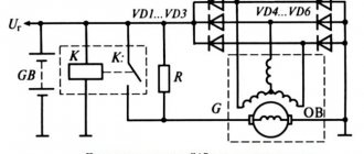
Many years ago, I made a similar regulator when I had to earn extra money repairing radios at a customer’s home. The regulator turned out to be so convenient that over time I made another copy, since the first sample was constantly installed as an exhaust fan speed regulator. https://oldoctober.com/
By the way, this fan is from the Know How series, as it is equipped with an air shut-off valve of my own design. Description of the design >>> The material can be useful for residents living on the top floors of high-rise buildings and who have a good sense of smell.
The power of the connected load depends on the thyristor used and its cooling conditions. If a large thyristor or triac of the KU208G type is used, then you can safely connect a load of 200... 300 Watts. When using a small thyristor, type B169D, the power will be limited to 100 Watts.
Construction and details
Now let's move on to the design of the device. Diode bridges, a capacitor, resistor R2 and diode VD6 are installed on a circuit board measuring 55x35 mm, made of foil getinax or textolite with a thickness of 1...2 mm (Fig. 9.7).
The following parts can be used in the device. Transistor - KT812A(B), KT824A(B), KT828A(B), KT834A(B,V), KT840A(B), KT847A or KT856A. Diode bridges: VD1...VD4 - KTs410V or KTs412V, VD6 - KTs405 or KTs407 with any letter index; diode VD5 - series D7, D226 or D237.
Variable resistor - type SP, SPO, PPB with a power of at least 2 W, constant - BC, MJIT, OMLT, S2-23. Oxide capacitor - K50-6, K50-16. Network transformer - TVZ-1-6 from tube TVs, TS-25, TS-27 - from the Yunost TV or any other low-power one with a secondary winding voltage of 5...8 V.
The fuse is designed for a maximum current of 1 A. The toggle switch is TZ-S or any other network switch. XP1 is a standard power plug, XS1 is a socket.
All elements of the regulator are housed in a plastic case with dimensions of 150x100x80 mm. A toggle switch and a variable resistor equipped with a decorative handle are installed on the top panel of the case. The socket for connecting the load and the fuse socket are mounted on one of the side walls of the housing.
On the same side there is a hole for the power cord. A transistor, transformer and circuit board are installed at the bottom of the case. The transistor must be equipped with a radiator with a dissipation area of at least 200 cm2 and a thickness of 3...5 mm.
Rice. Printed circuit board of a powerful 220V mains voltage regulator.
The regulator does not need to be adjusted. With proper installation and serviceable parts, it begins to work immediately after being plugged into the network.
Dinistor and 4 types of conductivity.
This device is called a trigger diode. Has little power. There are no electrodes in its interior.
The dinistor opens when the voltage increases. The speed at which voltage increases is determined by the capacitor and resistors. All adjustments are made through it. Works on direct and alternating current. You don’t have to buy it, it is in energy-saving lamps and is easy to get from there.
It is not often used in circuits, but in order not to spend money on diodes, a dinistor is used.
It contains 4 types: PNP N. This is the electrical conductivity itself. An electron-hole transition is formed between 2 adjacent regions. There are 3 such transitions in the dinistr.
Scheme:
We connect the capacitor. It starts charging with 1 resistor, the voltage is almost equal to that in the network. When the voltage in the capacitor reaches the level of the dinistor, it will turn on. The device starts working. Don't forget about the radiator, otherwise everything will overheat.
DIY adjustable power supply
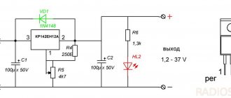
A power supply is a necessary thing for every radio amateur, because to power electronic homemade products you need a regulated power source with a stabilized output voltage from 1.2 to 30 volts and a current of up to 10A, as well as built-in short circuit protection. The circuit shown in this figure is built from the minimum number of available and inexpensive parts.
Scheme of an regulated power supply on an LM317 stabilizer with short-circuit protection
The LM317 IC is an adjustable voltage regulator with built-in short circuit protection. The LM317 voltage stabilizer is designed for a current of no more than 1.5A, so a powerful MJE13009 transistor is added to the circuit, capable of passing through itself a really high current of up to 10A, according to the datasheet, a maximum of 12A. When you rotate the knob of the variable resistor P1 by 5K, the voltage at the output of the power supply changes.
There are also two shunt resistors R1 and R2 with a resistance of 200 Ohms, through which the microcircuit determines the output voltage and compares it with the input voltage. 10K resistor R3 discharges capacitor C1 after the power supply is turned off. The circuit is powered by voltage from 12 to 35 volts. The current strength will depend on the power of the transformer or switching power supply.
I drew this diagram at the request of novice radio amateurs who assemble circuits using wall-mounted installations.
Scheme of an regulated power supply with short-circuit protection on LM317
It is advisable to carry out the assembly on a printed circuit board, so it will be beautiful and neat.
Printed circuit board of the regulated power supply on the LM317 voltage regulator
The printed circuit board is made for imported transistors, so if you need to install a Soviet one, the transistor will have to be unfolded and connected with wires. The MJE13009 transistor can be replaced with the MJE13007 from the Soviet KT805, KT808, KT819 and other npn structure transistors, it all depends on the current you need. It is advisable to reinforce the power paths of the printed circuit board with solder or thin copper wire. The LM317 voltage stabilizer and the transistor must be installed on a radiator with sufficient area for cooling; a good option is, of course, a radiator from a computer processor.
It is advisable to screw a diode bridge there. Don't forget to insulate the LM317 from the heatsink with a plastic washer and a heat conductive gasket, otherwise there will be a big boom. Almost any diode bridge can be installed with a current of at least 10A. Personally, I installed the GBJ2510 at 25A with double the power reserve, it will be twice as cool and reliable.
And now the most interesting part... Testing the power supply for strength.
I connected the voltage regulator to a power source with a voltage of 32 volts and an output current of 10A. Without load, the voltage drop at the output of the regulator is only 3V. Then I connected two series-connected halogen lamps H4 55 W 12V, the lamp filaments were connected together to create a maximum load, the result was 220 W. The voltage dropped by 7V, the nominal voltage of the power supply was 32V. The current consumed by four halogen lamp filaments was 9A.
The radiator began to heat up quickly, after 5 minutes the temperature rose to 65C°. Therefore, when removing heavy loads, I recommend installing a fan. You can connect it according to this diagram. You can not install the diode bridge and capacitor, but connect the L7812CV voltage stabilizer directly to capacitor C1 of the regulated power supply.
Connection diagram of the fan to the power supply
What happens to the power supply if there is a short circuit?
In the event of a short circuit, the voltage at the output of the regulator is reduced to 1 volt, and the current is equal to the current of the power source, in my case 10A. In this state, with good cooling, the unit can remain for a long time; after the short circuit is eliminated, the voltage is automatically restored to the limit set by the variable resistor P1. During the 10-minute short-circuit test, no parts of the power supply were damaged.
Radio components for assembling an adjustable power supply on LM317
- Voltage stabilizer LM317
- Diode bridge GBJ2501, 2502, 2504, 2506, 2508, 2510 and other similar ones designed for a current of at least 10A
- Capacitor C1 4700mf 50V
- Resistors R1, R2 200 Ohm, R3 10K all resistors with a power of 0.25 W
- Variable resistor P1 5K
- Transistor MJE13007, MJE13009, KT805, KT808, KT819 and other npn structures
Friends, I wish you good luck and good mood! See you in new articles!
I recommend watching a video on how to make an adjustable power supply with your own hands
How to Read Technical Data Sheets
As with most things, the answer to this question can be found on the Internet.
Here we describe how you can find reference sheets of technical data for products (their technical descriptions) produced by a particular manufacturer ( Fig. 14 ). First, find the component you are interested in from an email ordering supplier. Then Google the part number and manufacturer's name. Typically, data sheets for that component will be among the first search results. Using sources such as the Mouser Electronics website makes searching even easier by providing a direct link to technical data sheets for many products.
Rice. 14. A typical technical data sheet that includes the relevant technical specifications for a product, in this case a high efficiency LED in a 5mm diameter package.
Let's give an example. Let's say I want to use a red LED like the TLHR5400 from Vishay Semiconductor, which has become so common that I can buy it separately for $0.09 each. Click on the link to the technical data sheet provided by Vishay Semiconductor. Almost immediately, a PDF file page will appear on your computer screen. This data sheet is for LED types TLHR, TLHG and TLHY, which respectively have red, green and yellow colors, indicated by the letters "R", "G" and "Y" in the LED name. I scroll through the document and find the table “OPTICAL ELECTRICAL CHARACTERICS” (optical and electrical characteristics). It contains information that when the current through the LED is 20 mA, it has a typical value (“TYP.”) Forward voltage of 2 V. The word “MAX.” in the table means the maximum value, which is 3 V.
Now let's look at another data sheet since they all have the same shape. I'll choose another LED, Kingbright's WP7113SGC component. I click on the link on the manufacturer's website and I get the second page of the data sheet, where the typical forward voltage is 2.2V, the maximum is 2.5V, and the maximum forward current is 25mA. Also, I found some additional information: the maximum allowable reverse voltage is 5V, and the maximum allowable reverse current is 10uA (meaning a microamp, which is 1000 times smaller than an ampere). This data tells us that we should not apply excess voltage to the LED when connecting with reverse polarity. If the maximum permissible reverse voltage value for an LED is exceeded, there is a danger of its failure. Therefore, always try to maintain the correct polarity when connecting!
Kingbright provides information about the temperature the LED can withstand: 260°C (500°F) for a few seconds. This is useful information because pretty soon we'll be putting aside our alligator clips and using hot solder melted with a soldering iron to connect electrical components. Since we've already destroyed the battery, fuse, and LED in just four experiments, you probably won't see us ruining at least a few more components when determining their temperature limits when exposed to a soldering iron.
In any case, now we know what is needed for the LED to work properly, and we can do all the relevant calculations.
| Fundamentals |
| Ohm's law For reasons I'll explain later, electric current is usually represented by the letter "I". The letter "U" represents voltage and the letter "R" represents resistance, usually represented in ohms (since it is not easy to type the letter "Ω" using most keyboards). Using these symbols, you can write Ohm's law in three different ways: U = I × R.I = U/R.R = U/I.It should be remembered that U is the potential difference (voltage) between two points in a simple circuit, R is the resistance in ohms between those two points, and I is the current in amperes that passes through that circuit between the two points. The letter "I" is used because current strength is measured according to the inductance created by the current, which means the ability of the current to induce (create) a magnetic field. To designate electric current, the use of the letter “A” would raise much fewer questions, but, unfortunately, it is too late to change anything. |
| Basic information |
| What voltage drops across the wire? Usually, we can ignore the resistance of wires, for example, in short-length wires that connect resistances, since it is obvious. However, if you are trying to pass a large amount of current through a long, thin wire, then it becomes important to consider its resistance. How important is this? To determine this, we can again use Ohm's law. Let's assume that a very long piece of wire has a resistance of 0.2 ohms. Let's say we want to pass a current of 15 A through this wire. What voltage will be taken from the circuit due to its resistance? We begin again to write the equation that you already know: R = 0.2 Ohm I = 15 A We want to know the voltage U, the voltage drop, for the wire, so we'll use Ohm's law, which puts the voltage U on the left side of the equation: U = I × R.Now you need to put into this formula the values that were specified in the condition: U = 15 A × 0.2 Ohm = 3 V Three volts is not too much if you have a high voltage source, but if you are using, for example, a car battery with a voltage of 12 V, but a wire of that length will take a quarter of the available voltage in the circuit ( Fig. 15 ). Now you should understand why the wires in cars are quite thick - this is due to the fact that their resistance should be much less than 0.2 ohms.
|
| Fundamentals |
| Decimal separator position¹ Legendary British politician Sir Winston Churchill was famous for complaining about “those bloody dots.” He was aware of decimal points. Since Churchill was Chancellor of the Exchequer at this time and was responsible for all government spending, his difficulties with the use of decimal points created quite a lot of problems. Nevertheless, be that as it may, he always brought things to the end, which you will probably do too. Alternatively, you can use a pocket calculator - or the following two basic rules. When performing multiplication: move decimal points Let's assume. You need to multiply 0.04 by 0.005:
When performing division: cancel decimal points Let's assume. You need to divide 0.006 by 0.0002:
|
Types of Variable Resistors
Wire
It consists of a tubular plastic or ceramic frame, on which a thin wire with high resistance (manganin or constantan) is laid in the form of a single-layer winding.
A metal slider slides along the surface of the wire, which, when moved, touches the next turn of the winding before leaving the previous one - this ensures smooth adjustment.
To ensure reliable contact between the slider and the conductive layer, the surface of the wire is carefully polished.
Thin film
It consists of a frame in the form of a horseshoe-shaped dielectric plate coated with a thin film made of carbon, boron, metallized or composite materials. A slider, firmly connected to the adjustment mechanism, slides over the surface of the film.
Simple DIY CH
Parametric voltage stabilizer
A 12-volt voltage stabilizer for LEDs, backlights of automotive on-board systems is quickly and conveniently performed using microcircuits: LM317, LD1084, L7812, KREN 8B and similar devices. Several diodes, a resistance and the microcircuit itself are the components of such a circuit.
Stabilizer on LM317
Depending on the manufacturing option of the LM317 case, the arrangement of parts on the board is selected.
LM317 with heatsink mount
Making a stabilizer comes down to the following:
- a resistance with a nominal value of 130 Ohms is soldered to the output (Vout);
- a wire supplying voltage for stabilization is connected to the input contact (Vin);
- the adjustment input (Adj) is connected to the second terminal of the resistor.
When connecting LED lights, strips, etc. as a load. no radiator required. Assembly takes 15-20 minutes with a minimum of parts. Using a simple formula, you can calculate the value of resistance R to obtain a certain value of the permissible load current.
CH circuit on LM317
Circuit on the LD1084 chip
The use of this microassembly will help maintain the 12 V voltage constant for LED illumination devices connected to the vehicle’s on-board network.
Datasheet LD1084
Here, to assemble a homemade CH, the following is included in the circuit binding circuit of the microcircuit:
- two electrolytic capacitors of 10 μF * 25 V;
- resistors: 1 kOhm (2 pcs.), 120 Ohm, 4.7 kOhm (can be constant);
- diode bridge RS407.
The device is assembled as follows:
- the voltage removed from the rectifier diode bridge is supplied to the input of LD1084;
- the emitter of the KT818 transistor is connected to the contact that controls the stabilization mode (Adj), the base of which is connected through two single-column resistors to the power supply circuits for the headlights (low and high);
- the output circuit of the microcircuit is connected to resistors R1 and R2, as well as a capacitor.
By the way. Resistor R2 can be taken not as a variable, but as a tuning one, using it to set the output voltage to 12 V.
SN for on-board network
Stabilizer on diodes and assembly L7812
A similar microcircuit in conjunction with a diode and capacitors can supply LEDs with a stable voltage of 12 V.
The scheme is built according to the principle outlined below:
- The 1N401 Schottky diode passes current from the positive terminal of the battery through itself and supplies it to the input of the microcircuit. In this case, the “+” of the electrolyte (330 μF capacitor) is also connected to the cathode of the diode;
- a load circuit and a “+” capacitor with a capacity of 100 μF are connected to the output of L7812;
- all negative terminals (from the battery and both electrolytic capacitors) are connected to the control input of the microcircuit.
Electrolytic capacitors are selected for a voltage of at least 25 V.
12 V stabilizer circuit on IC L7812
The simplest stabilizer is the KREN board
Schemes using rolls are quite popular. This is the name for ICs whose markings include combinations of the letters KR and EN. These are powerful SNs that allow you to supply a current of up to 1.5 A to the load. They have a stable 12 V output when a voltage of up to 35 V is applied to the input.
The circuit using this microcircuit is assembled like this:
- voltage from the positive terminal of the battery (rechargeable battery) to the bank input is supplied through a 1N4007 diode, it protects the battery circuit from reverse voltages;
- the negative terminal of the battery is connected to the control electrode KREN;
- The output voltage is supplied to the load.
If necessary, the microcircuit is screwed to the radiator.
KR142EN8B, connection diagram
Assembling 12 V voltage stabilizers with your own hands using linear and integrated MV circuits is not difficult. In this case, it is necessary to monitor the heating temperature of the housing of the elements and, when T0C is higher than permissible, install them on heat sinks (radiators).
Checking an Individual Regulator
Checking the voltage regulator of the G-222 generator: 1 - battery; 2 - voltage regulator; 3 - control lamp.
As a rule, separate voltage regulators were installed on old cars, including domestic VAZs. But some manufacturers continue to do this to this day. The verification process is similar. To do this, you need to have a power supply with a voltage regulator, a 12 V light bulb, a multimeter and a directly tested regulator.
To check, you need to assemble the circuit shown in the figure. The process itself is similar to the one above. In normal condition (at a voltage of 12 V), the light bulb lights up. When the voltage value increases to 14.5 V, it goes out, and when it decreases, it lights up again. If during the process the lamp lights up or goes out at other values, it means that the regulator has failed.
Checking relay type 591.3702-01
Relay test diagram type 591.3702-01
You can also still find a voltage regulator of type 591.3702-01, which was installed on rear-wheel drive VAZs (from VAZ 2101 to VAZ 2107), GAZ and Moskvich. The device is mounted separately and installed on the body. In general, the test is similar to that described above, but the differences are in the contacts used.
In particular, it has two main contacts - “67” and “15”. The first of them is a minus, and the second is a plus. Accordingly, to check it is necessary to assemble the circuit shown in the figure. The verification principle remains the same. In normal condition, at a voltage of 12 V, the light bulb lights up, and when the corresponding value increases to 14.5 V, it goes out. When the value returns to its original value, the light comes on again.
A classic regulator of this type is a device of the PP-380 brand, installed on VAZ 2101 and VAZ 2102 cars. We provide reference data regarding this regulator.
| Adjustable voltage at regulator and ambient temperature (50±3)° C, V: | |
| at the first stage | no more than 0.7 |
| on the second stage | 14,2 ± 0,3 |
| Resistance between plug “15” and ground, Ohm | 17,7 ± 2 |
| Resistance between plug “15” and plug “67” with open contacts, Ohm | 5,65 ± 0,3 |
| Air gap between armature and core, mm | 1,4 ± 0,07 |
| Distance between second stage contacts, mm | 0,45 ± 0,1 |
Making your own device
Initially we need a 12 volt voltage regulator circuit. It needs to be etched and cleaned before it can be used in practice. Next, you should solder the necessary parts as indicated. And as a result, here is a pulse voltage stabilizer (12 volts, 1.5 Amperes), which can be used in a car to adjust the backlight. For convenience and protection, the entire device can be placed in a special container. It is advisable to use plastic as its material, which can easily withstand significant temperatures and ensures tightness. Conductive metals should only be used if there are insulators on the wires and all parts of parts that could potentially cause an electric shock.
Selecting a new generator relay
Selecting a new relay regulator is quite simple. It doesn’t even make much sense for a car enthusiast to understand what specific type of device it is. What he really should take advantage of are the electronic catalogs of advanced online stores - such stores have their own cross-code database and allow you to select both the original relay and its analogues. The search can be carried out using the following parameters:
- Vehicle VIN code;
- Code of an already installed relay. Painted or embossed on the device body;
- Vehicle data. We are talking about the make and model, the year of manufacture, and engine parameters.
The easiest way to search is by the code of the existing relay, since the device is easy to get to and it is always marked. By the way, it may be difficult to select analogues for relay regulators of the latest car models from German automakers
.
The device may have a program-controlled microprocessor in its element base (introduced by BMW
and
Audi
) and, as a rule, is produced only under the brand of the automaker - there are no analogues on the spare parts market.
Adjustment features
It makes sense to talk about this or that 12 volt regulator only if you provide additional data:
- DC or AC voltage must be regulated;
- what is the maximum current in the load;
- the magnitude of the potential difference in front of the regulator;
- load voltage parameters in the regulation range.
Each of the listed parameters is associated with certain technical solutions that are reflected in the diagram. The general circuit of the regulator is a load that is connected to some device. It is conventionally indicated by a rectangle in the diagram shown below. Inside this rectangle there may be one or another diagram that corresponds to the additional data mentioned above. The simplest regulator is a variable resistor. It allows you to regulate AC voltage without distortion. This resistor is also applicable for direct current.
Circuit with variable resistor.
Elementary diagram of the regulator
Circuit with variable resistor
If the potential difference at the input is significantly greater than 12 volts at the output, energy will be lost in the regulator. The variable resistor will generate heat. To avoid heat loss, it is necessary to use variable inductance on alternating current, which can be LATR. Its throughput is limited, as in a variable resistor, by the design of the moving contact. But if switching is permissible by placing jumpers with reliable contacts between the turns, a significant current can be obtained.
Inductive regulator
Another way to regulate 12 volt alternating voltage with your own hands is to change the inductance of the regulator. To do this, manually change either the gap or the number of turns specifically designed for this. An adjustable welding transformer used to power a voltaic arc is designed according to this principle. If the 12 volt voltage regulator does not have the properties of a stabilizer and is controlled by yourself, the potential difference across the load must be monitored with a voltmeter.
A variable resistor and variable inductance can also be used as a current regulator. In this case, it is necessary to monitor the current in the load with an ammeter. If the voltage parameters at the load are not specified, with the exception of its value of 12 V, you can regulate it with a dimmer. This can be a powerful regulator since it is usually thyristor based. And modern thyristors are produced for a very wide range of potential difference and current.
Checking the voltage relay
Calculator for calculating leakage current in a car
Calculation of permissible current leakage in a car |
Online calculator Checking the generator voltage regulator is sometimes necessary when problems with the battery begin to occur. In particular, it began to undercharge or overcharge. When such a malfunction occurs, it’s time to check the generator voltage regulator relay.
The relay should turn off at 14.8 V
The task of this simple device is to regulate the voltage of the electric current that is supplied from the generator to the battery. When it fails, the battery is either not charged enough or, on the contrary, overcharged, which is also dangerous, since this significantly reduces the battery life.
Agree that such a prospect is not very good because of one small detail. This is why it is so important to monitor the operating condition of the voltage regulator (it can also be called a pill or a chocolate bar). But in order to properly check the voltage regulator, you need to know its type and several important features.