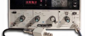
Potentiometer
(from Latin potentia - “power” and Greek μετρεω - “I measure”) - a measuring device designed to determine voltage by comparing two, in general, different voltages or EMF using the compensation method. When one of the voltages is known, it allows you to determine the second voltage.
Historically, the potentiometer is one of the first accurate voltage meters - voltmeters. Invented by German physicist Johann Poggendorff in 1841 [1].
A potentiometer (meter) should not be confused with a three-terminal variable resistor, an electronic component also colloquially known as a "potentiometer."
Sometimes “potentiometers” are not entirely correctly called displacement and rotation sensors based on a potentiometric circuit, for example, throttle position sensors in internal combustion engines.
Operating principle [edit | edit code ]
A potentiometer is a voltage divider made of resistors (resistive divider) with variable resistance (variable resistors).
A source whose voltage is known ( U 0 <0>>) and a source whose voltage needs to be determined ( U x > ) are connected to the voltage divider.
One of the voltages being compared, known with sufficient accuracy, is usually called the “reference voltage” or “reference EMF”. In foreign literature, the reference voltage is called “reference voltage” and is usually denoted U ref >.
By manually or automatically adjusting the resistance of the voltage divider, we ensure that the voltage UK > removed from the divider becomes equal to the voltage (or emf) U x > . Voltage equality (U x = UK =U_>) is usually called “stress balance”. The “balance” indicator is a sensitive low current (or voltage) meter, often called a “null indicator” and indicated in the figure by the letter “O”. When U x = UK, =U_,> the current I x > flowing through the zero indicator “O” will be equal to 0.
Historically, sensitive galvanometers were the first to be used as null indicators. In modern electronics, high-gain differential amplifiers are used as a null indicator.
For the diagram shown at the top of the figure, according to Kirchhoff’s rules
I x + IK = I 0 ; +I_=I_<0>;> U x = UK = IK ⋅ R 1 ; =U_=I_cdot R_<1>;> U 0 + I 0 ⋅ ( R 0 − R 1 ) + IK ⋅ R 1 = 0 , <0>+I_<0>cdot (R_<0>-R_<1> )+I_cdot R_<1>=0,>
and taking into account I x = 0 =0>:
IK = I 0 ; =I_<0>;> U x = I 0 ⋅ R 1 ; =I_<0>cdot R_<1>;> I 0 = U x R 1 ; <0>=>>>;> U 0 + I 0 ⋅ ( R 0 − R 1 ) + I 0 ⋅ R 1 = U 0 + I 0 ⋅ R 0 = 0 ; <0>+I_<0>cdot (R_<0>-R_<1>)+I_<0>cdot R_<1>=U_<0>+I_<0>cdot R_<0>=0;> U 0 = − I 0 ⋅ R 0 = − U x R 1 ⋅ R 0 ; <0>=-I_<0>cdot R_<0>=->>>cdot R_<0>;> U x = UK = − U 0 R 1 R 0 , =U_=-U_<0>>>, > 0>1>
For the diagram shown below the figure
U x = UK = − U 0 R 1 R 1 + R 2 . =U_=-U_<0>1>+R_<2>>>.> 1>
That is, knowing the ratio of the resistances of the voltage divider resistors when the voltages are equal (“balance”), one can numerically express one voltage ( U 0 <0>> or U x >) through another voltage ( U x > or U 0 <0>>, respectively ).
The flux chord was historically used as a variable resistance. The reochord was a piece of tensioned wire of a constant cross-section with three electrical leads. The first two leads were attached to the ends of the wire, and the third (slider) could be moved along the wire. The electrical resistance R of a homogeneous piece of wire of length l and constant cross-section S is expressed by the formula R = ρ l S, ho >,> where ρ ho > is the specific electrical resistance of the wire material. Knowing the length of the wire L, the distance l from the edge of the wire to the slider and the voltage U 0 <0>> between the ends of the wire, we can determine the voltage UK > (equal to U x > ) between the slider and the end of the wire:
U x = UK = − U 0 R 1 R 0 = − U 0 ρ l S ρ LS = − U 0 l L . =U_=-U_<0>>>=-U_<0>< ho >>< ho >>>=-U_<0>>.> 0>1>
Reochords, which are a piece of wire, are practically not used in modern potentiometers; they are only sometimes used for demonstration purposes. A modern rheochord is a variable resistor, usually made in the form of a single-layer spiral winding of high-resistance wire on a straight or toroidal base (frame). The name "reochord" in potentiometers is firmly attached to these variable resistors.
Historically, electrochemical sources of time-stable and reproducible voltage—normal electrochemical cells—have been used as a reference voltage source (RV). In modern potentiometers, semiconductor precision IONs are usually used as reference voltage sources - temperature-compensated zener diodes and bandgap IONs.
If loading a source of known voltage onto a resistive voltage divider is unacceptable, for example, in the case of using sources with high internal resistance, then another source with a sufficiently low internal resistance is preliminarily calibrated against this source.
When the voltages of the resistive divider and the reference voltage are balanced, the current through the null indicator (galvanometer) is zero. Thus, the reference voltage source operates at idle balance, which allows precision sources with high internal resistance, such as normal electrochemical cells, to be used as reference voltage sources. Similarly, for the same reason, it is possible to measure the EMF of unknown voltage sources with high internal resistance without distorting the measurement result, for example, the EMF of electrochemical potentiometric sensors.
Applications
Potentiometers are rarely used to directly control significant amounts of power (more than a watt or so). Instead, they are used to adjust the level of analog signals (such as surround controls for audio equipment), and as control input signals for electronic circuits. For example, a dimmer uses a potentiometer to control the switching of the TRIAC and thus indirectly control the brightness of the lamps.
Preset potentiometers are widely used in electronics wherever adjustment is required during production or service.
User-controlled potentiometers are widely used as user controls and can control a very wide range of hardware functions. The widespread use of potentiometers in consumer electronics declined in the 1990s as rotary incremental encoders, up/down buttons, and other digital controls became more common. However, they remain in many applications such as volume controls and position sensors.
Audio control
Slider potentiometers ( )
Low power potentiometers, either slide or rotary, are used to control audio equipment, changing volume, attenuating frequency, and other characteristics of audio signals.
A "log pot", that is, a potentiometer having a resistance, cone or "curve" (or law) of a logarithmic (logarithmic) shape, is used as a volume control in audio power amplifiers, where it is also called an "audio cone pot" because the amplitude The characteristic of the human ear is approximately logarithmic. This ensures that on a volume control labeled 0 to 10, for example, a value of 5 subjectively sounds twice as loud as a value of 10. There is also an anti-logarithmic potentiometer
or
an inverse sound cone,
which is simply an inverse logarithmic potentiometer. It is almost always used in a group configuration with a logarithmic potentiometer, such as in an audio balance control.
Potentiometers, used in conjunction with filter networks, act as tone controls or equalizers.
In audio systems, the word linear is sometimes used to describe slide potentiometers in a confusing manner due to the linear nature of the physical sliding movement. The word linear, when applied to a potentiometer, whether sliding or rotating type, describes the linear relationship of the position of the potentiometer to the measured value of the tap pin (wiper or electrical output) of the potentiometer.
A television
In the past, potentiometers were used to control the brightness, contrast, and color response of an image. A potentiometer was often used to adjust the "vertical hold", which affected the timing between the receiver's internal sweep circuit (sometimes a multivibrator) and the received image signal, along with other things such as AV carrier offset, tuning frequency (for pressing the -button), and etc. It also helps with frequency modulation of the waves.
Motion Control
Potentiometers can be used as position feedback devices to create closed-loop control, such as in a servomechanism. This motion control method is the simplest method for measuring angle or displacement.
Converters
Potentiometers are also very widely used in displacement sensors due to their simplicity of design and the fact that they can produce a large output signal.
Calculation
In analog computers, high-precision potentiometers are used to scale intermediate results by desired constant factors or to set initial conditions for a calculation. A motor driven potentiometer can be used as a function generator, using a nonlinear resistance map to provide an approximation to trigonometric functions. For example, the rotation of a shaft can be an angle, and the voltage division factor can be made proportional to the cosine of the angle.
Features of potentiometers for measuring ultra-low voltages [edit | edit code ]
When measuring ultra-low voltages (at the level of microvolts - fractions of a millivolt), the distortion of the measurement result from the thermo-EMF of “parasitic” thermocouples formed at the points of electrical connection of dissimilar conductor materials (for example, copper conductors and high-resistance conductors of variable resistors) becomes significant if the temperature of these connections (joints) is not equal. Without the use of special measures, the values of parasitic thermo-EMF can reach tens of microvolts. For example, the thermo-EMF of a copper-tin-lead solder pair is about 3-7 µV/K, which, when the measured voltage is in the range of a few to tens of microvolts, can give a relative measurement error of several tens of percent, which is usually unacceptable. Therefore, when designing such potentiometers, special measures are used to reduce parasitic thermo-EMF. A radical measure is careful thermal insulation of the device from the external environment, sometimes thermostatting. For soldering electrical connections, solders are used that produce low thermal EMF when paired with copper, for example, tin-cadmium solders, whose thermal EMF when paired with copper is less than 0.3 μV/K.
Precious materials in potentiometers:
EPP-09M and EPV-2-11A contain 1.441 g. silver, but not gold, palladium or platinum. EPR-09 contains 2.832 grams of silver and 11.859 grams of palladium, but no gold or platinum. EPPV-60 does not contain gold, platinum and palladium, like EPP-09M and EPPV-2-11A, but the silver content is 0.181. The silver content in EPV-2 is 1.86 g, and gold, palladium and platinum are absent. P-39, P-37-1, P-37/1, P-363-1, P-363-2 and P-363-3 contain no gold, palladium or platinum, but the silver content of P-39 is 63.081 , in P-37-1 - 14.161, in P-37/1 - 14.992, in P-363-1 - 28.547. P-363-2 also contains 28.547 grams of silver, while P-363-3 contains 50.781. P4833 contains neither platinum nor palladium, but contains 0.036 gold and 6.68 silver. P-363 contains no platinum, gold or palladium, but has a silver content of 18.4. Potentiometers P-362/2, P-355, P-348, P-306, P-307, PP-63 contain neither gold, nor silver, nor platinum, nor palladium. The silver content in P-362/2 is 28.547, in P-355 - 18.76, in P-348 - 7.88. P-306 contains 7.241 grams of silver, P-307 contains 15.713, and PP-63 contains 1.0572. In PZ-9, gold is 0.359, and silver is 30.119. PDS-021 contains 0.411 g. silver There is no platinum in PDP4-002, the gold content is 0.549, silver - 3.143, and palladium - 12.54. The PDP-4-002 potentiometer contains 0.5 g of gold and 1.566 g of palladium. In PDP-4, silver is 05, palladium is 1.761. In P5-28 Au - 0.287, Ag - 217.33, Pd (palladium) - 0.8. In P5-27 Au – 0.63, Ag – 181.03, Pd – 1.59. In the P5-25 potentiometer, Au is 0.18, Ag is 295.7, Pd is 1.023. In P3-26, Au is 0.22, Ag is 171.58, Pd is 1.59. In OD-61 there are 15.031 g of silver. LPM-60 contains 1.22 g of palladium. LOMO-200 contains 1.48 g of silver. In LKD-4 Au – 0.6, Ag – 4.6, Pd – 12.5. In potentiometers KSU1-080, KSU1-079, KSU1-066 and KSU1-065 Au - 0.447, Pd - 6.389. In KSU1-076, KSU1-075, KSU1-062 and KSU1-061, KSU1-036 Au - 0.127, Pd - 2.969. In KSU1-074, KSU1-073, KSU1-072, KSU1-071, KSU1-060, KSU1-059, KSU1-058 and KSU1-057 Au - 0.447, Pd - 9.44.
Recording and recording automatic potentiometers [edit | edit code]
In addition to measuring potentiometers, in which balancing (changing the resistance of the resistive divider until the measured voltage is equal to the voltage taken from the slider) is performed manually, there are potentiometers with automatic balancing. Automatic devices are widely used, for example, in recorders (process recorders on paper tape), which are still common in industrial process control systems. Electromechanical potentiometers are gradually being replaced by digital devices for storing and displaying information.
Read also: DIY gearbox for a concrete mixer
The operating principle of automatic potentiometers is based on the use of a tracking electromechanical automatic control circuit. The measured voltage and the voltage from the slider motor are fed to a differential mismatch amplifier, the output of which controls the reversible electric motor through a power amplifier. The electric motor, through mechanical elements (cables, gears), moves the slider motor in the desired direction so as to reduce the mismatch signal to zero. The slider engine is rigidly connected to the pointing arrow, which moves along a scale digitized in units of the measured value. The scale does not have to be digitized in voltage units; for example, when the device is operated in conjunction with some kind of thermal converter, it can be digitized in degrees of temperature; when working with a glass electrode, it can be digitized in pH units (pH meter). In recorders, the pen moves along the paper at the same time as the pointer. The pen draws a line on the paper and thereby records the change in the measured value, usually depending on time.
A potentiometer is a product that performs the functions of regulating electric current. Additionally, the device can cope with the operation of a rheostat. For all models of potentiometers, resistors are used with tap contacts of various lengths.
In the field of electronics, these products are very popular. The main difference between the models can be considered the total number of supported cycles.
The products have a through resistance of about 7 ohms . Very often, such devices are used to adjust the volume. They are also used in various measuring instruments. The maximum adjustment range of the potentiometer depends on the elements with which it is assembled. Next, let's look at how a potentiometer works and its types.
Mechanical potentiometers
A mechanical potentiometer is a product for regulating electric current , which is equipped with a special rotary controller. There are several pins at the bottom of the device. Electronic keys must be of the resistive type. And also in such products a program sampling function is provided. The maximum value of through resistance does not exceed 4 Ohms. Such products are not equipped with a calibration function. The negative electrical voltage of such a device is about 4 volts, and linear distortion does not exceed 92 decibels.
Powerful resistors should only be used of the open type. Mechanical potentiometers are ideal for reversing control. Many products do not support rheostatic mode. It is worth noting that such devices are not used to control the gain. The maximum positive electrical voltage is about 2.5 volts. The cutoff frequency very rarely exceeds 2500 kilohertz . The bandwidth value is directly dependent on the characteristics of the electronic key. Such products are not usually used in computing devices.
Electronic potentiometers
An electronic potentiometer is a product necessary to regulate electric current. Many models are equipped with several electronic keys. Powerful resistors should only be used of the resistive type. To reverse control the equipment, you can use almost any product model. These devices can withstand up to 12 continuous control cycles. Almost all models have a software sampling function. It is worth noting that electronic products can be used to control volume. The value of linear distortion of such devices does not exceed 85 decibels .
Electronic products are quite often used in computing equipment, because their cutoff frequency is no more than 3100 kilohertz. The bandwidth of the electronic key is about 4 microns, but it largely depends on the manufacturer. Many models of such potentiometers are used for high-quality adjustment of various filters. It is worth noting that this device cannot perform gain adjustment.
Integrate Potentiometer with Arduino
There's a lot you can do with an Arduino board and a potentiometer But before that you should know that to make a simple example where you will start to see how the potentiometer works, you can use any of the analog pins on your board. For example, in Arduino UNO you can use A0 to A5.
Since they have 10-bit resolution, this means you have 1024 possible values (0000000000-1111111111), and since the available voltage range is 0V to 5V, it can be calibrated so that 0000000000 (or 0) is 0 V, and 1111111111 (or 1023) was 5 V so it could detect voltage spikes of 0.004 V (5/1024).
to link , you can simply do the following:
- Connect the potentiometer input to the 5V board.
- The output of the potentiometer will be connected to one of the analog inputs. For example, A1.
- As for the other remaining potentiometer pin, you should connect it to GND.
Once this is done, you can create a small sketch in the Arduino IDE to be able to test how the potentiometer works. With this code you will be able to read the voltage values obtained from the output when you turn the potentiometer cursor.
//Ejemplo de prueba de potenciómetro long valor; void setup() { //Inicialisamos la comunicación serial Serial.begin(9600); //Escribir el valor leído por el monitor serie Serial.println("Inicio de sketch - Valores del potenciómetro"); } void loop() { // Leer los valores del A1 valor = analogRead(A1); //Imprimir en el monitor serie Serial.print("Valor leído = "); Serial.println(valor); delay(1000); }
For more information you can...
How to connect the device correctly
Required tools and materials
To properly connect the device with your own hands, you need the following tools and materials:
- working potentiometer;
- set of wires;
- regular scissors;
- powerful soldering iron;
- special solder;
- measuring voltmeter;
- ball pen.
Potentiometer connection
You must connect the product yourself in the following sequence:
- The working sensor should be positioned in such a way that the special lever for regulating the electrical voltage is directed straight up, and the terminals for securing the wires are located near the person. The pins must be numbered from left to right using a ballpoint pen.
- The first pin must be connected to ground. To do this, you should cut a wire of a certain length and solder it well.
- The second terminal is necessary to secure the wire that sends electrical voltage to the sensor output.
- The third pin must be soldered to the input of the circuit.
- Next, after completing the previous steps, it is worth testing the correct operation of the sensor. To do this, you should use a measuring device. When performing this work, it is necessary to rotate the sensor slider from the lowest to the highest electrical voltage value. You can learn more about how to check the potentiometer from numerous photos on the Internet.
- After checking the quality of the sensor, you need to place it in the electrical circuit, and after that you need to cover the product with a protective casing.
In this article we will take a detailed look at potentiometers, consider the principle of operation, the potentiometer in the diagram and types.
How to repair diesel injectors
Before removing the fuel injector from a diesel engine, it is necessary to carry out external cleaning of the junction between it and the cylinder head. The fact is that the slightest grain of sand when removing an element can be death for the injector needle. They should be unscrewed using spanners so as not to erase the edges.
To remove high pressure fuel pipes, make special marks on them. This will help in the future to correctly assemble the elements. After removal, install protective caps on them to avoid contamination.
Otherwise, cleaning diesel engine injectors is almost no different from cleaning gasoline injectors. The only difference is the use of other types of cleaning products.
Despite the simplicity of the procedure, cleaning diesel injectors may not always be successful. The fact is that diesel fuel has different properties, and cleaning injectors usually ends with replacing them. In addition, a serious reason for replacement may be a malfunction of the atomizer, spring, as well as wear of the needle itself. To avoid bringing the injector to this state, cleaning diesel injectors should be a preventive measure that can extend the life of the part.
This is how to clean, check the fuel injectors and repair the throttle potentiometer. All these procedures can be done independently, which saves money on visiting a car service center.
Description and principle of operation
Resistors provide a fixed value of resistance that blocks or resists the flow of electrical current around a circuit and also causes a voltage drop according to Ohm's law. Resistors can be made to have either a fixed resistance value in ohms or a variable resistance value adjusted by some external means.
A potentiometer , commonly referred to as a "boiler", is a three-terminal mechanically driven rotary analog device that can be found and used in a wide variety of electrical and electronic circuits. They are passive devices, meaning they do not require a power supply or additional circuitry to perform their primary function of linear or rotary position.
Variable potentiometers are available in a variety of mechanical variations, allowing easy adjustment of voltage control, current control, or bias and gain control of the circuit to obtain the null state.
Read also: How to charge pinky batteries
The name "potentiometer" is a combination of the words "potential difference" and "measurement", which appeared in the early days of electronics. It was then believed that by adjusting large resistive wire-wound coils, a set amount of potential difference was measured, making it a type of voltage measuring instrument.
Today, potentiometers are much smaller and much more accurate than those that used to be large and bulky variable resistance ones, and as with most electronic components, there are many different types and names, ranging from variable resistor, preset, trimmer, rheostat, and , of course, a variable potentiometer.
But whatever their names, all these devices function exactly the same, since their output resistance value can be changed by the movement of a mechanical contact or contact brush caused by some external influence.
Variable resistors in any format are usually associated with some form of control, be it adjusting radio volume, vehicle speed, generator frequency, or fine-tuning circuit calibration, single-turn and multi-turn potentiometers, trimmers and rheostats can find wide application in household electrical products.
The terms potentiometer and variable resistor are often used to describe the same component, but it is important to understand that the connections and operation of the two devices are different. However, both have the same physical properties in that the two ends of the internal resistive trace are brought out to contacts, in addition to a third contact connected to a movable contact called a "slider" or "contact brush".
Where and for what are voltage dividers used?
PTs normalize voltage; more often they are used to adjust application parameters (serviced equipment) within the normal values for which it is designed, when such a function is built into it, for example, sound volume, fan speed. The most common model is with manual adjustment, but there is also an automatic integrated potentiometer.
PT is also used when it is necessary to establish the desired mode of equipment in difficult conditions, when a certain level of electrical parameters can disable the application, or for research, for the purposes of maintenance, repair, experiments, and adjustment.
An increase/decrease in U supplied to the load, which also entails changes in current, is carried out by potentiometers or rheostats. We will look at the difference between them below. In fact, these terms do not denote the part itself (in all cases this is a variable resistor), but the modes of its inclusion in the circuit.
The most typical examples of what is regulated:
- power and other parameters (adjustment by equalizers) of sound, video brightness/shades, light (dimmers);
- speed of low-power electric motors of household appliances and toys;
- Fans with variable speed settings have voltage dividers. Even those whose rotation intensity is meant to be set to constant operation with a certain value? often have a trimmer on the chip;
- generator frequency;
- calibration of electrical circuits, on microcircuits for adjusting electrical parameters by voltage (its output power).
- Precision, including automatic high-precision potentiometer is used in angular and linear displacement sensors.
Variables/trimmers are used wherever adjustment of the output voltage is required. But you need to understand that such a device is needed only for high-resistance loads and low currents. Where these parameters are large, rheostats are used. For example, the dimmer may contain a DC, but if the incandescent lamp is powerful, then it will be useless and a PC must be used. The same applies to electric motors: low-power ones can be regulated by PT, but powerful power plants in vehicles have RS. In order to study where to apply what, you need to do calculations using Ohm's formulas.
Potentiometer on the diagram
When using a potentiometer, connections are made at both ends and also to the contact brush as shown in the figure. The position of the contact brush provides a corresponding output signal (pin 2) that will vary between the voltage level applied to one end of the resistive trace (pin 1) and the voltage level at the other (pin 3).
The potentiometer is a three-wire resistive device that acts as a voltage divider, producing a continuously varying voltage output that is proportional to the physical position of the contact brush along the trace.
What types of potentiometers are there?
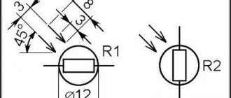
There are three types of potentiometers, systematized by the nature of the change in resistance:
- Linear potentiometers, which are designated by the letter A. The resistance changes in direct proportion to the angle of rotation of the sliding contact.
- Logarithmic potentiometers, designated B. The resistance changes quickly at first and then changes more slowly.
- Exponential potentiometers (changing resistance exponentially), which are usually designated by the letter C. The resistance changes slowly at first and then becomes faster, unlike logarithmic potentiometers.
Variable resistor in the diagram
When using a variable resistor, connections are made to only one end of the resistive track (pin 1 or 3) and the contact brush (pin 2), as shown in the figure. The position of the contact brush is used to change the amount of effective resistance connected to each other, the moving contact and the fixed end.
Sometimes it is advisable to make an electrical connection between the unused end of the resistive trace and the contact brush to prevent open circuit conditions.
A variable resistor is then a two-wire resistive device that provides an infinite number of resistance values that control the current offered to the connected circuit, proportional to the physical position of the contact brush along the trace. Note that variable resistors used to control very high circuit currents found in lamps or motor loads are called rheostats.
Peculiarities
The device itself is small and round in size. Its body most often contains the basic data necessary for the user. As a rule, this is a dustproof case made of durable material. It is manufactured together with the gear in the seat.
There are up to thirty-two varieties, each designed for specific tasks. Each of them complies with the rules OST V 25 21-86. It is used in two cases: to regulate voltage and regulate current.
Types of Potentiometers
Variable potentiometers are an analog device consisting of two main mechanical parts.
1. A fixed or stationary resistive element, track or wire coil that defines its resistance value, such as 1 kOhm, 10 kOhm, etc.
2. The mechanical part that allows the contact to move along the entire length of the resistive track changes its resistance value as it moves. There are many different ways to move a contact across a resistive track, either mechanically or electrically.
But along with the resistive track and wiper, potentiometers also contain a housing, a shaft, a slide block, and a bushing or bearing. The sliding contact movement itself can be a rotary (angular) action or a linear (direct) action. There are four main groups of variable potentiometer.
Rotary potentiometer
A rotary potentiometer (the most common type) changes its resistance value as a result of angular movement. Rotation of a knob or dial attached to the shaft causes the internal contact to move around the curved resistive element. The most common use of a rotary potentiometer is as a volume control.
Carbon rotary potentiometers are designed to be mounted on the front panel of a housing, enclosure, or printed circuit board (PCB) using a ring nut and lock washer. They can also have one single resistive track or multiple tracks known as a group potentiometer, in which all rotate together using one single rod. For example, a pot with two gangs for simultaneously adjusting the left and right volume levels of a radio or stereo amplifier. Some rotating pots have switches.
Rotary potentiometers can produce linear or logarithmic output with tolerances typically ranging from 10 to 20 percent. Because they are mechanically controlled, they can be used to measure shaft rotation, but a single-turn rotary potentiometer typically offers less than 300 degrees of angular movement from minimum to maximum resistance. However, there are multi-turn potentiometers called trimmers that provide a higher degree of rotational accuracy.
Multi-turn potentiometers allow the shaft to rotate through more than 360 degrees of mechanical movement from one end of the resistive track to the other. Multi-turn pots are more expensive but very stable with high precision, used mainly for trimming and fine adjustment. The two most common multi-turn potentiometers are 3-turn (1080 o) and 10-turn (3600 o), but 5-turn, 20-turn, and higher 25-turn pots are available with a variety of ohmic values.
Sliding potentiometer (slider)
Slider potentiometers or sliders are designed to change the value of their contact resistance through linear movement, and as such, there is a linear relationship between the position of the slide contact and the output resistance.
Slide potentiometers are primarily used in a wide range of professional audio equipment such as studio mixers, faders, graphic equalizers and audio control desks, allowing users to see from the position of a plastic square knob or finger grip the actual slide setting.
One of the main disadvantages of slide potentiometers is that they have a long open slot that allows the contact tip to move freely up and down the entire length of the resistive trace. This open slot makes the internal resistive track susceptible to contamination from dust and dirt, as well as sweat and grease from the user's hands. Slotted felt covers and screens can be used to minimize the impact of track contamination.
Since a potentiometer is one of the simplest ways to convert a mechanical position into a proportional voltage, they can also be used as resistive position sensors, also known as linear displacement sensors. Moving carbon track potentiometers measure precise linear (straight) motion, with the sensing part of the linear sensor being a resistive element attached to a sliding contact. This contact is in turn attached via a rod or shaft to the mechanical mechanism to be measured. The position of the slider then changes depending on the measured quantity (measured quantity), which in turn changes the resistance value of the sensor.
Presets and trimmers
Preset or trim pots are small, set-it-and-forget-it potentiometers that allow you to easily make very fine or random adjustments in a circuit (for example, for calibration). Single-turn rotary potentiometers are miniature versions of a standard variable resistor designed to be mounted directly on a printed circuit board, and are adjusted using a small-bladed screwdriver or similar plastic tool.
Read also: Can a burner be used as a soldering iron?
Typically, these preset linear carbon channel cans have an open frame design or a closed square shape, which once the circuit is configured and installed at the factory, then remain at that setting and are adjusted again only if problems occur. some changes in the circuit settings.
Being an open design, frame presets are subject to mechanical and electrical degradation affecting performance and accuracy, so they are not suitable for continuous use, and therefore preset pots are only designed for a few hundred operations. However, their low cost, small size, and simplicity make them popular in non-critical circuit applications.
Presets can be adjusted from minimum to maximum within one turn, but for some circuits or equipment this small adjustment range may be too coarse to provide very sensitive settings. However, multi-turn variable resistors operate by moving a contact lever. using a small screwdriver several turns, ranging from 3 to 20 turns, allowing for very precise adjustment.
Trim potentiometers or "trims" are multi-turn rectangular devices with linear guides that are designed to be mounted and soldered directly to a circuit board through a through hole or surface mount. This gives the trimmer both electrical connections and mechanical mounting, and enclosing the track in a plastic housing avoids the problems of dust and dirt during use associated with frame presets.
Rheostats
Rheostats are the big boys of the potentiometer world. They are two variable connection resistors configured to provide any resistive value within their ohmic range to control the flow of current through them.
Although in theory any variable potentiometer can be configured to act as a rheostat, rheostats are typically large, high-power wirewound variable resistors used in high current applications, since the main benefit of a rheostat is their higher power rating.
When a variable resistor is used as a two-pole rheostat, only the portion of the total resistive element that is between the terminal terminal and the moving contact will dissipate power. In addition, unlike a potentiometer, which is designed as a voltage divider, all current flowing through the resistive element of the rheostat also passes through the contact circuit. Then the contact pressure of the contact on this conductive element must withstand the same current.
Potentiometers are available in various technologies such as carbon film, conductive plastic, sintered metal, wire wound, etc. The nominal or "resistive" value of a potentiometer or variable resistor refers to the resistive value of the entire stationary resistance path from one fixed contact to the next. So a potentiometer rated at 1k would have a resistive track equal to the value of the fixed 1k resistor.
In its simplest form, the electrical operation of a potentiometer can be considered the same as that of two resistors in series, with a sliding contact changing the values of the two resistors, allowing it to be used as a voltage divider.
In our lesson on series resistors, we saw that the same current flows through a series circuit because there is only one path for the current, and we can apply Ohm's law to find the voltage drops across each resistor in the series circuit. The series resistive circuit then acts as a voltage divider network as shown in the figure.
In this example above, two resistors are connected in series across the power supply. Since they are in series, the equivalent or total resistance, RT, is therefore equal to the sum of the two individual resistors, that is: R 1 + R 2 .
Also being a series network, the same current flows through each resistor with nowhere to go. However, the voltage drop across each resistor will be different due to the different ohmic values of the resistors. These voltage drops can be calculated using Ohm's law with their sum equal to the supply voltage in the series circuit. So in this example V IN = V R1 + V R2.
The principle of operation of the potentiometer - briefly | Article
Have you ever had to adjust something using sliders or rotary knobs? Audio system volume level, vacuum cleaner operating mode, equalizer frequency amplitude? Or perhaps you are a more advanced user who adjusts the parameters of electronic boards? In any of these cases, you have had to deal with potentiometers.
Potentiometer
, as such, is a voltage divider with three terminals. The central terminal is the adjustable point contact, and the remaining two are resistance terminals. The principle of operation of the device is that by operating an adjustable point, you can influence the voltage between it and one of the terminals.
If you use only one of the outputs, you get a regular variable resistor
, allowing you to adjust various parameters. In this mode, the potentiometer can be used for control via the panel, and trimmers can be used to calibrate the electrical circuit.
A conventional potentiometer moves the entire adjustable point in one turn of the adjusting screw. Such potentiometers are cheap and easy to manufacture. However, in some situations their accuracy does not meet the objectives. Then multi-turn potentiometers come to the rescue.
Multi-turn potentiometer
- this is a resistor in which the full movement of the adjustable point occurs in a certain number of screw turns, which significantly increases the accuracy of the adjustment.
For example, turning the knob of a 10 kOhm single-turn potentiometer half a turn will change the resistance to 5000 Ohms, which, with a 10% tolerance, will give an error of 500 Ohms.
A multi-turn potentiometer of 10 turns with the same rating and tolerance with this rotation will give an error of only 50 ohms, which is only 0.5% of the rating.
In addition, with the development of technology, potentiometers are evolving: digital potentiometers have appeared, which are a special chip.
Depending on the specific purpose, they may have different housing options, tolerance percentages, linear or logarithmically varying resistance.
Understanding the principle of operation of a potentiometer is necessary
, because we interact with them every day, they surround us constantly - almost every electronic device contains this element in one way or another.
If you have difficulty selecting electronic components, please contact our managers for advice by phone, via email: [email protected] or through an online consultant. DIP8.ru specialists will help you sort through the catalog of potentiometers and find the necessary element according to the specified technical characteristics.
Also pay attention!
New models of potentiometers have arrived at our warehouse
:
- 3314G-1-502E
- 534B1502JCB
- RS6011DY-10KDX2
Types according to the “cone” - the nature of the change in resistance
“Cone” or “law” is the relationship between resistance. and the position of the scraper. Manufacturer controlled. Any ratio is possible, but for most tasks linear and logarithmic PTs (“sound cone”) will suffice.
A letter code may be used, but this is not standardized; it may be different for different manufacturers, but usually the marking is as follows:
- Asia and the USA. A - for logarithmic, C - for inverse logarithmic (rare, exponential) and B - for linear taper;
- Europe - A for linear, C and B for logarithmic, F for its inverse version.
Explanation
The percentage relating to the non-linear cone refers to the resistance index. at the midpoint of shaft rotation. The 10% cone of a log measures 10% of the total R on it. That is 10% logarithm. a cone on a 10 kOhm PT gives 1 kOhm at the indicated mark. The higher the percentage, the steeper the logarithm. curve.
Purchase of potentiometers PTP, PPML, PLP, PPMF, PPBL, prices
We will buy potentiometers presented on this page at high prices on an ongoing basis throughout the Russian Federation and neighboring countries. We have been working with individuals for more than 6 years.
Special-purpose potentiometers come in the following brands: PPML-M, PPML-I, PPML-IM, PPML-F, PPMF-M, PPBL-V, RPP, PTP-1, PTP-2, PTP-5, PLP-1, PLP -2. The table below shows photos and prices for suitable potentiometers. Some potentiometers, such as PTP 5, come with nichrome or manganin wire. As a rule, in such potentiometers the number 5 is in a white rectangle. For more details, see the photo of the built potentiometer PTP 5 and other photos of parts.
Separately, by clicking on the word More details, you will be redirected to the PPML Potentiometers page, where you will receive information about which potentiometers are suitable for sale for scrap. You can also get additional information about the content of precious metals in potentiometers on the Potentiometers page. Precious metal content.
Please note that the actual content of precious metals in potentiometers differs from the table value and ranges from 20-30% of that stated in the table. The exact price is determined only after disassembling and weighing the wire.