• Gradual increase in temperature and its exit beyond the permissible limit:
• insufficient cooling
• high ambient temperature
• low atmospheric pressure (work at high altitudes above sea level)
• high temperature of the working fluid
• too high viscosity of the working fluid
• frequent switching on/off of the electric motor
• too high load moment of inertia (different for each pump)
• Sudden rise in temperature:
• rotor blocking
• phase failure
To protect the network from overloads and short circuits when any of the above failure conditions occur, it is necessary to determine which network protection device will be used. It should automatically turn off power from the network. A fuse is a simple device that performs two functions. As a rule, fuses are connected to each other using an emergency switch, which can disconnect the motor from the power supply. In the following pages we will look at three types of fuses in terms of their operating principle and applications: fuse switch, fast-blow fuses and time-lag fuses.
Fusible safety switch
A safety switch is an emergency switch and a fuse combined in a single housing. A switch can be used to open and close a circuit manually, while a fuse protects the motor from overcurrent. Switches are typically used in connection with maintenance work when it is necessary to interrupt the current supply.
The emergency switch has a separate casing. This cover protects personnel from accidental contact with electrical terminals and also protects the switch from oxidation. Some emergency switches are equipped with built-in fuses, other emergency switches are supplied without built-in fuses and only have a switch.
The overcurrent protection device (fuse) must distinguish between overcurrent and short circuit. For example, minor short-term overcurrents are quite acceptable. But if the current increases further, the protection device must operate immediately. It is very important to prevent short circuits immediately. A fused switch is an example of a device used for overcurrent protection. Properly selected fuses in the switch open the circuit during current overloads.
Fast-blow fuses
Fast-blow fuses provide excellent short-circuit protection. However, short-term overloads, such as motor starting current, can cause this type of fuses to break. Therefore, fast-blow fuses are best used on circuits that are not subject to significant transient currents. Typically, these fuses will withstand about 500% of their rated current for one-fourth of a second. After this time, the fuse insert melts and the circuit opens. Therefore, in circuits where the inrush current frequently exceeds 500% of the fuse rated current, fast-blow fuses are not recommended.
Time delay fuses
This type of fuse provides both overload and short circuit protection. Typically, they allow 5 times the rated current for 10 seconds, and even higher current values for shorter periods. This is usually enough to keep the motor running and prevent the fuse from opening. On the other hand, if overloads occur that last longer than the melting time of the fuse element, the circuit will also open.
Fuse response time
The fuse operating time is the time it takes for the fuse element (wire) to melt for the circuit to open. Fuses have an operating time that is inversely proportional to the current value - this means that the greater the overcurrent, the shorter the period of time for the circuit to trip.
In general, we can say that pump motors have a very short acceleration time: less than 1 second. In this regard, time-delay fuses with a rated current corresponding to the full load current of the electric motor are suitable for electric motors.
The illustration on the right shows the principle of generating the fuse response time characteristic. The x-axis shows the relationship between actual current and full load current: if the motor draws full load current or less, the fuse will not open. But at a current value 10 times the full load current, the fuse will open almost instantly (0.01 s). The y-axis shows the response time.
During starting, a fairly large current passes through the induction motor. In very rare cases this results in shutdown via relays or fuses. To reduce the starting current, various methods of starting an electric motor are used.
What is a circuit breaker and how does it work?
An automatic current switch is an overcurrent protection device. It automatically opens and closes the circuit at a preset overcurrent value. If the current switch is used within the range of its operating parameters, opening and closing does not cause any damage to it. Immediately after an overload occurs, you can easily resume operation of the circuit breaker - it is simply reset to its original position.
There are two types of circuit breakers: thermal and magnetic.
Thermal circuit breakers
Thermal circuit breakers are the most reliable and economical type of protective devices suitable for electric motors. They can withstand the large current amplitudes that occur during motor starting and protect the motor from faults such as locked rotor.
Magnetic circuit breakers
Magnetic circuit breakers are accurate, reliable and economical. The magnetic circuit breaker is resistant to temperature changes, i.e. Changes in ambient temperature do not affect its operating limit. Compared to thermal circuit breakers, magnetic circuit breakers have a more precisely defined response time. The table shows the characteristics of two types of circuit breakers.
Operating range of circuit breaker
Automatic circuit breakers differ in the level of operating current. This means that you should always select a circuit breaker that can withstand the highest short circuit current that may occur in a given system.
What is it for?
Special phase controllers are in demand in places where it is necessary to frequently connect to the power supply and where it is important to observe their alternation. As an example, the situation is usually considered when the connected equipment is constantly transferred from one place to another. In this case, the probability of mixing up the phases of linear voltages is very high.
In some loads, incorrect alternation of them can lead to improper operation of the device and subsequent breakdown. Any unit connected to such a network for a long time is likely to fail. When operating such a device, you can easily make a mistake in assessing its condition, believing that the device needs repair.
Overload relay functions
Overload relay:
• When starting the electric motor, they allow you to withstand temporary overloads without breaking the circuit.
• Open the motor circuit if the current exceeds the maximum permissible value and there is a risk of damage to the motor.
• They are reset automatically or manually after the overload has been removed.
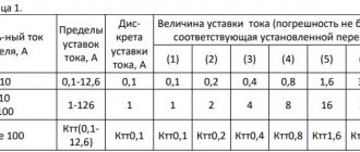
IEC and NEMA standardize trip classes for overload relays.
Trigger class designation
Typically, overload relays respond to overload conditions according to their tripping characteristics. For any standard (NEMA or IEC), the division of products into classes determines how long the relay requires to open when overloaded. The most common classes are: 10, 20 and 30. The digital designation reflects the time required for the relay to operate. A Class 10 overload relay operates in 10 seconds or less at 600% full load current, a Class 20 relay operates in 20 seconds or less, and a Class 30 relay operates in 30 seconds or less.
The angle of inclination of the response characteristic depends on the protection class of the electric motor. IEC motors are usually tailored to a specific application. This means that the overload relay can handle excess current that is very close to the relay's maximum capacity. Class 10 is the most common class for IEC motors. NEMA motors have a larger internal capacitor, so Class 20 is more commonly used.
Class 10 relays are typically used for pump motors, as the acceleration time of electric motors is about 0.1-1 second. Many high inertia industrial loads require a Class 20 relay to operate.
Combination of fuses with overload relays
Fuses serve to protect the installation from damage that may be caused by a short circuit. For this reason, fuses must have sufficient capacity. Lower currents are isolated using an overload relay. Here, the rated current of the fuse does not correspond to the operating range of the electric motor, but to the current that can damage the weakest components of the installation. As mentioned earlier, a fuse provides short circuit protection but not low current overload protection.
The figure shows the most important parameters that form the basis for the coordinated operation of fuses in combination with an overload relay.
It is important that the fuse blows before other parts of the installation suffer thermal damage from the short circuit.
Fuse
Fuse switches are quite simple in design and are considered the most common devices for electrical protection of motors.
This type of protection device has an emergency switch and a fuse.
The first is necessary to manually disconnect the device from the network. This may be necessary for urgent repairs or any other engine maintenance work.
As for the fuse, it serves in cases where the situation is unforeseen. If one of the above accidents occurs, the fuse turns off the device until the problem is resolved.
But there are cases when small jumps are acceptable and shutdown is not required at all. Then all the tension goes into the defense itself. There are devices of this type with different response periods.
Thus, they provide reliable motor overload protection.
Setting up an external overload relay
The full load current at a certain voltage indicated on the nameplate is the standard for setting the overload relay. Since different countries have different voltages, pump motors can be used at both 50 Hz and 60 Hz over a wide voltage range. For this reason, the motor nameplate indicates the current range. If we know the voltage, we can calculate the exact current carrying capacity.
Example calculation
Knowing the exact voltage value for the installation, the full load current at 254 / 440 YB, 60 Hz can be calculated.
The data is displayed on a nameplate as shown in the illustration.
Calculations for 60 Hz
The voltage gain is determined by the following equations:
Calculation of actual full load current (I):
(Current values for delta and star connections at minimum voltages)
(Current values for delta and star connections at maximum voltages)
Now, using the first formula, you can calculate the full load current:
I for "triangle":
I for "star":
The values for full load current correspond to the permissible motor full load current at 254 Δ/440 Y V, 60 Hz.
Attention : The external motor overload relay is always set to the rated current value indicated on the nameplate.
However, if motors are designed to have a load factor, which is then indicated on the nameplate, e.g. 1.15, the current setting for the overload relay can be increased by 15% compared to full load current or service factor amps (SFA). ), which is usually indicated on the nameplate.
Nuances when choosing
To select the optimal model of phrase control relay, engineer Rick advises paying attention to these parameters:
- supply voltage indicators;
- the importance of voltage reduction and control;
- ability to adjust the response delay time;
- response time;
- number of communication terminals;
- rated power indicator.
Important! In addition to technical characteristics, pay attention to the form factor of the device case. The best option would be to install it on a standard DIN rail.
Internal protection built into windings or terminal box
Why do you need built-in motor protection if the electric motor is already equipped with an overload relay and fuses? In some cases, the overload relay does not detect motor overload. For example, in situations:
• When the motor is closed (insufficiently cooled) and slowly reaches a dangerous temperature.
• At high ambient temperatures.
• When the external motor protection is set to trip current too high or is installed incorrectly.
• When the motor is restarted several times within a short period of time and the starting current heats up the motor, which can ultimately damage it.
The level of protection that internal protection can provide is specified in IEC 60034-11.
Designation TP
TP is an abbreviation for thermal protection. There are different types of thermal protection, which are designated by the code TP (TPxxx). Code includes:
• Type of thermal overload for which the thermal protection was designed (1st digit)
• Number of levels and type of action (2nd digit)
• Category of built-in thermal protection (3rd digit)
In pump motors, the most common TP designations are:
TP 111: Gradual overload protection
TP 211: Protection against both rapid and gradual overload.
| Designation | Technical load and its options (1st digit) | Number of levels and functional area (2nd digit) | Category 1 (3rd digit) |
| TR 111 | Slow only (constant overload) | Level 1 when disabled | 1 |
| TR 112 | 2 | ||
| TR 121 | 2 levels for alarm and shutdown | 1 | |
| TR 122 | 2 | ||
| TR 211 | Slow and fast (constant overload, blocking) | Level 1 when disabled | 1 |
| TR 212 | 2 | ||
| TR 221 TR 222 | 2 levels for alarm and shutdown | 1 | |
| 2 | |||
| TR 311 TR 321 | Fast only (blocking) | Level 1 when disabled | 1 |
| 2 |
Illustration of the permissible temperature level when the electric motor is exposed to high temperatures. Category 2 allows higher temperatures than Category 1.
All Grundfos single-phase electric motors are equipped with motor current and temperature protection in accordance with IEC 60034-11. The type of motor protection TP 211 means that it responds to both gradual and rapid temperature increases.
The device is reset and returned to its initial position automatically. Grundfos MG three-phase electric motors with power from 3.0 kW are equipped as standard with a PTC temperature sensor.
These motors have been tested and approved as TP 211 motors, which respond to both slow and rapid temperature rises. Other electric motors used for Grundfos pumps (MMG models D and E, Siemens, etc.) can be classified as TP 211, but as a rule they have protection type TP 111.
The information on the nameplate must always be observed. Information about the type of protection of a particular motor can be found on the nameplate - marking with the letter TP (thermal protection) according to IEC 60034-11. Typically, internal protection can be provided using two types of protection devices: Thermal protection devices or thermistors.
Thermal protection devices built into the terminal box
Thermal protection devices, or thermostats, use a bimetallic, instantaneous dial-type circuit breaker to open and close a circuit when a certain temperature is reached. Thermal protection devices are also called “klixons” (after a trademark from Texas Instruments). Once the bimetallic disk reaches a predetermined temperature, it opens or closes a group of contacts in the connected control circuit. Thermostats are equipped with contacts for either normally open or normally closed operation, but the same device cannot be used for both modes. Thermostats are pre-calibrated by the manufacturer and their settings cannot be changed. The discs are hermetically sealed and located on the contact block.
The thermostat can supply voltage to the alarm circuit if it is normally open, or the thermostat can de-energize the motor if it is normally closed and connected in series with the contactor. Since the thermostats are located on the outer surface of the ends of the coil, they react to the temperature at their location. When applied to three-phase motors, thermostats are considered unstable protection under braking conditions or other conditions of rapid temperature change. In single-phase electric motors, thermostats serve to protect against blocked rotor.
Thermal circuit breaker built into the windings
Thermal protection devices can also be built into the windings, see illustration.
They act as a mains switch for both single-phase and three-phase electric motors. For single-phase motors up to 1.1 kW, the thermal protection device is installed directly in the main circuit to act as a winding protection device. Klixon and Thermic are examples of thermal circuit breakers. These devices are also called PTO (Protection Thermique a Ouverture).
Indoor installation
Single-phase motors use one single thermal circuit breaker. In three-phase electric motors there are two series-connected switches located between the phases of the electric motor. Thus, all three phases are in contact with the thermal switch. Thermal circuit breakers can be installed at the end of the windings, but this results in longer response times. The switches must be connected to an external control system. This protects the electric motor from gradual overload. For thermal circuit breakers, a relay amplifier is not required.
Thermal switches DO NOT PROTECT the motor when the rotor is locked.
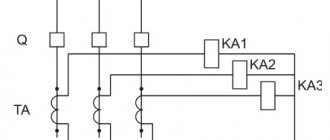
Design and operating principle
Rice.
1. Design of the relay using the example of the CKF-2BT device. Structurally, the device includes input and output contacts, indicators of normal power supply and emergency, regulators, indicated in the diagram by the corresponding numbers (Figure 1):
- Emergency indicator;
- Indicator of connected load power supply;
- Potentiometer allowing you to select the desired mode;
- Asymmetry level regulator;
- Voltage reduction regulator;
- Potentiometer that allows you to adjust the time setting.
Not all models provide the full range of settings for the above parameters. They depend on the purpose of the specific relay and the scope of application.
Rice. 2. Schematic diagram of operation
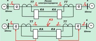
In normal mode, voltage is supplied to the power circuit from the EMF source E1 (Figure 2) to the consumer, be it an engine, a machine tool or other equipment. The phase control relay R is connected to the tap through the corresponding terminals, designated in the diagram as L1, L2, L3 and the neutral wire N. A logical circuit on transistors is assembled inside the device, which sends a signal from the output contacts to break the starter coil P to turn off. If necessary, the shutdown signal can be configured to both de-energize the consumer and disconnect the external electrical network.
In the event of an emergency - loss of one of the phases, short circuit, sharp increase in currents, the harmonic component of the electrical parameters of the network changes. To which the protection device reacts and sends a corresponding shutdown signal through the power circuits through terminals 24 and 21 to the contactor coil.
After the activation of power contacts in the practice of power supply to consumers, a natural restoration of the parameters of the supply network can occur, during which phase alignment will occur. In this case, the relay will return the contacts to the on position, due to which the automatic reclosure system is implemented and the voltage supply to the windings of the motor or other consumer will be resumed.
Using the “Start” and “Stop” buttons, you can manually control the power of an electrical device.
Operating principle of thermal circuit breaker
The graph on the right shows resistance versus temperature for a standard thermal circuit breaker. Each manufacturer has its own characteristics. TN usually lies in the range of 150-160 °C.
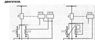
Connection
Connection of a three-phase electric motor with built-in thermal switch and overload relay.
TP symbol on the chart
Protection according to IEC 60034-11:
TP 111 (gradual overload). In order to provide protection when the rotor is blocked, the electric motor must be equipped with an overload relay.
Thermistors built into windings
The second type of internal protection is thermistors, or positive temperature coefficient (PTC) sensors. Thermistors are built into the windings of the electric motor and protect it when the rotor is blocked, prolonged overload and high ambient temperatures. Thermal protection is provided by monitoring the temperature of the motor windings using PTC sensors. If the winding temperature exceeds the shutdown temperature, the sensor resistance changes according to the temperature change.
As a result of this change, the internal relays de-energize the control circuit of the external contactor. The electric motor cools down, and the acceptable temperature of the electric motor winding is restored, and the sensor resistance drops to its original level. At this moment, the control module is automatically reset to its original position, unless it has previously been configured to reset the data and turn it on again manually.
If the thermistors are installed at the ends of the coil themselves, the protection can only be classified as TP 111. The reason is that the thermistors do not have full contact with the ends of the coil, and therefore cannot respond as quickly as if they were originally built into the winding.
The thermistor temperature sensing system consists of positive temperature coefficient (PTC) sensors installed in series and a solid state electronic switch in an enclosed control box. The set of sensors consists of three - one per phase. The resistance in the sensor remains relatively low and constant over a wide temperature range, with a sharp increase at the response temperature. In such cases, the sensor acts as a solid state thermal circuit breaker and de-energizes the monitoring relay. The relay opens the control circuit of the entire mechanism to turn off the protected equipment. When the winding temperature is restored to an acceptable value, the control unit can be returned to its previous position manually.
All Grundfos electric motors with power from 3 kW and above are equipped with thermistors. A positive temperature coefficient (PTC) thermistor system is considered to be fault tolerant because when a sensor fails or a sensor wire is disconnected, infinite resistance occurs and the system responds in the same way as when the temperature rises - de-energizing the control relay.
Typical connection diagrams
In most cases, the manufacturer installs all the necessary data on the method of connecting a particular relay on the housing of each device. As an example, let’s take several circuits from well-known manufacturers:
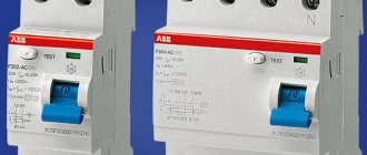
Connection diagram RKF RNPP-311
The diagram shows the connection of the terminal row to the corresponding phases of the line L1, L2, L3 and neutral N. At the output, it is possible to obtain two control circuits “Output 1” and “Output 2”, differing in voltage levels.
OMRON relay connection diagram
Power is supplied through the input channels L1, L2, L3 and through the neutral N. At the output, there are two options: a three-phase three-wire system and a three-phase four-wire system, for working with the corresponding switch.
Connection diagram for RKF Carlo Gavazzi
Unlike previous versions, the input terminals L1, L2, L3 are powered through fuses. The parameter adjustment block allows you to adjust the corresponding operating mode and shutdown limits according to them. Two outputs with the possibility of manual switching send control signals to switch certain devices.
The last two diagrams demonstrate the operation of the secondary load disconnect circuits with the corresponding time delay across these terminals. As you can see, all connection diagrams have identical components designed to monitor all network parameters that can signal a failure in the power supply to three-phase consumers.
Operating principle of a thermistor
The critical values of the resistance/temperature relationship for motor protection sensors are defined in DIN 44081/DIN 44082.
The DIN curve shows the resistance in thermistor sensors as a function of temperature.
Compared to PTO, thermistors have the following advantages:
• Faster response due to lower volume and weight
• Better contact with the motor winding
• Sensors are installed on each phase
• Provide protection when the rotor is blocked
Types of AMR
According to the method of voltage regulation, one-, two-, three-phase devices are distinguished:
- Soft starter with voltage regulation in one phase.
They are used in electric drives of equipment with a power of 11 kW. Such soft starters ensure a reduction in dynamic shocks and the absence of jerks when starting the drive. The disadvantages of devices of this type are asymmetrical load at startup and large inrush currents. - Two-phase soft starters.
Used in drives with power up to 250 kW to reduce dynamic loads during startup. Provide some reduction in starting currents and engine heating. Used in equipment with moderate starting conditions in the absence of strict current limiting requirements. - Three-phase soft starters.
Soft starters of this type reduce starting currents to 3 times the nominal value, allow for a smooth stop, and provide emergency shutdown of the drive. Voltage regulation is carried out in all three phases, which eliminates the occurrence of asymmetry. The rated power of the drive is limited only by the characteristics of the semiconductor power elements. Such soft starters are used in drives with particularly difficult starting conditions, with frequent starts and stops.