DC electric motors, now widely used in everyday life and in production, have many advantages, but are characterized by high starting currents. There are several common options for connecting such electric motors.
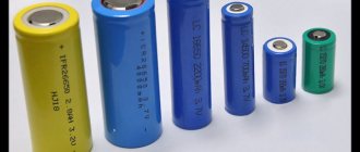
Thanks to the excellent traction capabilities of DC electric motors, electrical equipment assembled on their basis has become widespread, both in everyday life and in production. Such motors can often be found in modern children's toys, fans, power tools and autonomous industrial electrical installations. They are an integral part of vehicle control and electrification systems. Batteries or rechargeable batteries of different capacities are usually used as a power source.
The DC motor also has many other advantages, including:
- simple speed adjustment;
- possibility of soft start and smooth increase in speed;
- the ability to accelerate to speeds of over three thousand revolutions per minute.
Despite all these advantages, a DC electric motor has a more complex design than an asynchronous AC power unit of 380 or 220 volts, which implies some difficulties in its operation. In addition, there is a danger of significant inrush currents, so there are different ways to connect DC motors, each of which has its own characteristics and nuances. To better understand them, let's take a closer look at the design, operating principle and connection of a DC motor.
DC motor. Connection diagrams and characteristics of DPT
The DC motor has found wide application in various fields of human activity.
Starting from the use of traction drives used in trams and trolleybuses, ending with the drive of rolling mills and lifting mechanisms, where maintaining high precision of rotation speed is required. The main positive features that distinguish a DPT from an asynchronous motor:
| — flexible starting and adjustment characteristics; |
| — two-zone regulation, which allows you to achieve rotation speeds of more than 3000 rpm. |
Negative features:
| - difficulty in manufacturing and high cost; |
| — during operation, constant maintenance is necessary, since the collector and current-collecting brushes have a short service life. |
A DC motor is used only when the use of an AC motor is impossible or extremely impractical. On average, for every 70 AC motors there is only 1 DC motor.
DPT design
The DC motor consists of:
| — inductor (stator); |
| - armature (rotor); |
| — collector; |
| — current collection brushes; |
| — structural elements. |
The armature and the inductor are separated by an air gap. The inductor is a frame that serves to secure the main and additional poles of the motor’s magnetic system. The main poles have excitation windings, and the additional poles have special windings that help improve switching.
The collector supplies direct current to the working winding, which is placed in the slots of the rotor. The collector has the form of a cylinder and consists of plates isolated from each other; it is mounted on the engine shaft. The brushes are used to remove current from the commutator; they are mounted in brush holders to ensure the correct position and reliable pressure on the surface of the commutator.
Figure 1 – DC motor design
DC motors are classified according to the stator magnetic system:
1) DFC with permanent magnets;
2) DFC with electromagnets:
| — DPT with independent excitation; |
| — DBT with sequential excitation; |
| — DPT with parallel excitation; |
| — DBT with mixed arousal. |
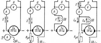
Figure 2 – DC motor connection diagrams
The connection diagram of the stator windings significantly affects the electrical and traction characteristics of the drive.
Starting a DC Motor
The DC motor is started using starting rheostats, which are active resistances connected to the armature circuit. Rheostatic starting is performed for two reasons:
| — if necessary, smooth acceleration of the electric motor; |
| - at the initial moment of time, the starting current Iп = U / Rя is very large, which causes overheating of the armature winding (which has low resistance). |
Only DFCs with a power of up to 1 kW are allowed to start without starting rheostats, the so-called “direct start”.
Figure 3 – Rheostatic engine starting with 3 stages
At the beginning of the start-up, all resistances are connected to the rotor circuit, and as the speed increases, they are removed in steps.
Rotation speed regulation
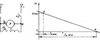
The rotational speed of a DC motor is expressed by the formula:
This expression is also called the electromechanical characteristic of the DPT, in which:
| U – supply voltage; |
| Iа – current in the armature winding; |
| Rya – anchor chain resistance; |
| k – motor design coefficient; |
| Ф – magnetic flux of the motor. |
Engine torque formula:
Substituting the electromechanical characteristics into the formula, we get:
Thus, based on the above formulas, we conclude that the rotation speed of the DC motor can be adjusted by changing the armature resistance, supply voltage and magnetic flux.
Direct start of electric motor
A low-power electric motor (up to one kilowatt) is easiest to turn on directly. Like connecting a 380V three-phase motor, this start of a DC electric motor P involves supplying voltage from the power source directly to the working winding. Since there is no natural compensation due to the counteracting electromotive force, the inrush current reaches its maximum value.
If we consider direct connection from a physics point of view, the situation looks like this. Initially, when the motor starts, the current strength has a value determined by the formula: I=U/R, where U is the rated voltage, R is the resistance of the coils. In this case, the current load reaches its maximum value and can be more than twice the nominal value.
Further flow of current initiates the appearance of an electromotive counterforce, which acts as a kind of brake, normalizing the starting load to rated power. The current strength is now calculated using a different formula: I=U-E/R, where E is the counter emf.
In powerful power units, for example, crane motors DK213MD2, the resistance of the rotor windings can reach one Ohm, which provokes the occurrence of a starting current of up to 500 amperes, which is tens of times higher than the permissible value. This can cause thermal sinking of the metal, melting and deformation of wires, damage to contact brushes and rings, and also creates an increased risk of electric shock to operating personnel. Therefore, to turn on electric motors of medium (for example, series D) and high power, it is recommended to use rheostats, special regulators or a deliberately low voltage. Direct launch is contraindicated for them.
Three-phase brushless DC motor
This type of motor has excellent characteristics, especially when controlled by position sensors. If the resistive torque varies or is completely unknown, or if it is necessary to achieve a higher starting torque, sensor control is used. If the sensor is not used (usually in fans), the control allows you to do without wired communication.
Features of controlling a three-phase brushless motor without a position sensor:
- the rotor location is determined using a differential ADC (analog-to-digital converter);
- current overload is also determined using an ADC (analog-to-digital converter) or an analog comparator;
- speed adjustment is performed using PWM channels connected to the lower drivers;
- AT90PWM3 and ATmega64 are considered recommended microcontrollers;
- The supported communication interfaces (communication interfaces) are UART, SPI and TWI.
Features of controlling a three-phase brushless motor with a position sensor using the example of a Hall sensor:
- speed adjustment is performed using PWM channels connected to the lower drivers;
- the output of each of the Hall sensors is connected to the corresponding I/O line of the microcontroller, configured to generate interrupts when the state changes;
- supported communication interfaces (communication interfaces) are UART, SPI and TWI;
- current overload is determined using an ADC (analog-to-digital converter) or an analog comparator.
Electric motor device
The main elements that make up a typical three-phase motor are:
- A housing having legs with which it is attached to the foundation;
- A stator whose structure resembles a simple transformer. It has a core and a winding. When current is applied, a vortex electromagnetic field is created.
- Rotor. Main rotating part.
- The shaft on which the rotor is rigidly mounted. The front part extends outward and has a keyway for gears or a pulley. An impeller for cooling and airflow is mounted on the rear part, extending beyond the body.
- Bearings located in the niches of the front and rear covers.
- Sealed terminal box.
Briefly about the main thing
You can connect a 380 to 220 volt electric motor in 4 main ways:
- With capacitor.
- Without capacitor.
- With reverse.
- Star-delta design.
Before starting connection work, it is necessary to determine and verify how the winding is connected in the terminal box, and also find out the necessary characteristics from the technical table. You can perform electrical work if you have experience, but it is better to entrust it to professionals with the appropriate permit.
Classification of MPT according to the method of powering the inductor and armature windings
Based on this feature, MPTs are divided into 4 types.
With independent excitation
The inductor and armature windings have no electrical connection. In generators of this type, the excitation winding is powered by a direct current network, a battery, or a generator specially designed for this purpose - an exciter. The power of the latter is several hundredths of the power of the main generator.
Scope of application of generators with independent excitation:
- systems of significant power, where the voltage on the excitation winding differs significantly from the generated one;
- systems for regulating the rotation speed of engines powered by generators.
For motors with independent excitation, the armature winding is also energized. Basically these are also high-power units.
The independence of the inductor winding makes it more convenient and economical to regulate the excitation current. Another feature of such motors is the constancy of the excitation magnetic flux under any load on the shaft.
With parallel excitation
The inductor and armature windings are connected in one circuit parallel to each other. Generators of this type are usually used for medium power. In a parallel connection, the voltage generated by the device is applied to the excitation winding. When the inductor and armature windings are connected into one circuit, they speak of a self-excited generator.
In terms of their characteristics, they are identical to motors with independent excitation and have the following features:
- when the load changes, the rotation speed is practically not transformed: the deceleration is no more than 8% when transferring from idle to rated load;
- it is possible to regulate the rotation speed with minimal losses, and within a wide range - 2 times, and for specially designed motors, 6 times.
The inductor of a rotating parallel-wound motor cannot be disconnected from the armature circuit, even if it is already disconnected. This will lead to the induction of a significant EMF in the excitation winding with subsequent failure of the motor. Personnel nearby may be injured.
With sequential excitation
The windings are connected in series to each other. The armature current flows through the field winding. Generators of this type are almost never used, since the process of self-excitation occurs quite rapidly and the device is not able to provide the constant voltage required by most consumers. They are used only in special installations.
Series excitation circuit
Motors of this type are widely used as traction motors (electric locomotives, trolleybuses, cranes, etc.): compared with parallel excitation analogues, when loaded they produce a higher torque with a simultaneous decrease in rotation speed. The starting torque is also high.
Starting the engine with a load below 25% of the rated load, and even more so at idle, is unacceptable: the rotation speed will be too high and the unit will fail.
With parallel-series (mixed) excitation
There are two types of scheme:
- the main winding of the inductor is connected in parallel with the armature winding, the auxiliary winding is connected in series;
- The main winding of the inductor is connected in series with the armature winding, the auxiliary winding is connected in parallel.
Schemes of MPT excitation systems
Connecting a parallel winding before a series winding is called a “short shunt”, and after a series winding - a “long shunt”. Generators of this type are used extremely rarely.
The engines combine the advantages of analogues with parallel and series excitation: they are able to operate at idle speed and at the same time develop significant traction force. But they are almost never used today.
Connection methods for 220V
To connect a three-phase asynchronous electric motor to a 220-volt network, there are several proven methods:
- With capacitor.
- Without capacitor.
- With reverse.
- Combined star-delta circuit.
Let's look at them in more detail.
Important! When connecting a 380-volt electric motor to a 220-volt network, you need to be prepared to reduce its power to 70% of the factory value. However, in everyday conditions this is quite acceptable and will not affect the performance in any way.
Connecting a 380 V motor to 220 V Source ytimg.com
With capacitor
The most popular and affordable way to initiate 380 volt motors from a 220 V network is a circuit using a capacitor. Its role is to create a phase shift in the windings relative to each other in order to form a rotating magnetic field. If there are three phases, this phenomenon occurs by itself - only one will not force the rotor to rotate. Therefore, the optimal method for connecting an electric motor with 4 wires on one phase is to use a starting winding, in addition to the main winding, in 220V electric motors.
For the 380 V modification, two connection options with a capacitor are possible:
- With working capacitor Cp .
- And parallel connected working Cp and starting capacitor Sp .
In the second case, the engine starts more smoothly and safely. Sp module turns on for a short period of time and turns off as the rotor reaches the required speed. The choice of starting option is largely determined by the degree of rotor load during starting. So, if the start occurs without force, only Cp , and if under load, without free rotation, the presence of Cn .
Connecting a motor with capacitors Source blogspot.com
Pros - cons
The technical characteristics of asynchronous electric motors with a squirrel-cage rotor are so superior to those of synchronous ones that most drives are made on their basis.
The advantages of such devices are:
- Reliability, simplicity of design, durability;
- No difficulties in repair and maintenance;
- By switching 2 phases, you can make the shaft rotate in the opposite direction;
- Application as a generator.
There are also disadvantages or disadvantages:
- If the phasing is incorrect, the shaft can rotate in the wrong direction and jam other mechanics (gears);
- Inrush current up to five times the rated current;
- Acceleration and braking speed. Some devices with high inertia require higher power motors.
- If a phase is broken, the motor may burn out if the voltage supply is not turned off in a timely manner.
Connection to single-phase and three-phase power supplies
According to the type of supply network, AC electric motors are classified into single- and three-phase.
Connecting asynchronous single-phase motors is very easy - to do this, just connect the phase and neutral wires of a single-phase 220V network to the two outputs on the housing. Synchronous motors can also be powered from this type of network, but the connection is a little more complicated - it is necessary to connect the rotor and stator windings so that their single-pole magnetization contacts are located opposite each other.
Connecting to a three-phase network seems a little more complicated
First of all, you should pay attention that the terminal box contains 6 pins - a pair for each of the three windings. Secondly, this makes it possible to use one of two connection methods (“star” and “delta”)
Incorrect connection can damage the motor by melting the stator windings.
The main functional difference between “star” and “triangle” is the different power consumption, which is done to enable the machine to be connected to three-phase networks with different line voltages - 380V or 660V. In the first case, the windings should be connected in a “triangle” pattern, and in the second case, in a “star” pattern. This switching rule allows in both cases to have a voltage of 380V on the windings of each phase.
On the connection panel, the winding terminals are located in such a way that the jumpers used for switching on do not cross each other. If the motor terminal box contains only three terminals, then it is designed to operate on one voltage, which is indicated in the technical documentation, and the windings are interconnected inside the device.
Definition of connection diagram
Before choosing one or another scheme for connecting a motor to 220 V, it is necessary to determine what the connection diagram for its winding is and at what rating it can generally be operated. To do this you need:
- Find and study the technical table on the engine. characteristics .
The information field contains all the important information - designation of the type of connection ∆ - triangle or star - Y , power, number of revolutions, voltage (220 or 380, or 220/380) and the possibility of connecting according to a specific circuit.
- Open the terminal box and verify in practice that the assembled circuit is correct.
The beginning and end of each winding is signed in accordance with the above alphanumeric nomenclature. The user remains to study the connection diagram using jumpers: according to what scheme the connection is made - star or triangle.
Note! If the nameplate (table with information) indicates the Y and only 380V, then when it is connected in a triangle, the winding will burn out. Only professional electricians can upgrade such a 220V motor. Therefore, there is no reason to modify it, especially since today there are many copies that can operate alternatively - both 220 and 380 volts.
Opening the terminal box Source pikabu.ru
See also: Catalog of companies that specialize in electrical work
Current Applications and Prospects
There are many devices for which increasing uptime is critical. In such equipment, the use of BDKP is always justified, despite their relatively high cost. These can be water and fuel pumps, cooling turbines for air conditioners and engines, etc. Brushless motors are used in many models of electric vehicles
Currently, the automotive industry is seriously paying attention to brushless motors.
BDKPs are ideal for small drives operating in difficult conditions or with high precision: feeders and belt conveyors, industrial robots, positioning systems. There are areas in which brushless motors dominate without alternative: hard drives, pumps, silent fans, small household appliances, CD/DVD drives. The low weight and high power output have also made the BDKP the basis for the production of modern cordless hand tools.
Connection via Arduino chip
Low power engines can also be started using special functional platforms. A common method now is to connect a DC motor to Arduino. It is better not to connect directly via Arduino, since there is a high probability of damaging the chip. It is recommended to use an H-bridge or transistors. This technology for introducing electric motors into functional circuits provides many opportunities for controlling and driving the working parts of electric machines, modern vehicles and robotic mechanisms. You can control not only the speed of the motor, but also the direction of its movement.
Direct connection to the platform output ports will not only cause them to burn out, but will also reduce the motor control functionality to a minimum. Each such port can supply a current of about twenty milliamps, and for normal operation even the most compact electric motor requires many times more. Therefore, the motor must be connected to the Arduino in series through a current regulator.
When choosing a suitable motor for connection to a microcontroller, you should pay attention to the following characteristics:
- current consumption required for normal operation of the equipment;
- nominal voltage (the most common for such systems is 12 volts);
- rotational moment - the greater it is, the more powerful the unit;
- speed of rotation of the electric motor shaft;
- weight and dimensions - preference is now given to miniature models.
The easiest way is to serially connect a standard brushed DC motor to Arduino, designed for a current of up to 5A and an operating voltage of about 9V. A transistor system is often used for this. But it only allows you to control the speed of revolutions. Connecting to a microcontroller via an H-bridge also makes it possible to adjust the direction of rotation.
Principle of operation
The operation of the engine is that the controller switches a certain number of stator windings in such a way that the vector of the magnetic fields of the rotor and stator are orthogonal. Using PWM (pulse width modulation), the controller controls the current flowing through the motor and regulates the torque exerted on the rotor. The direction of this acting moment is determined by the mark of the angle between the vectors. Electrical degrees are used in calculations.
In such a situation, the resulting vector shifts and becomes stationary with respect to the rotor flow, which, in turn, creates the necessary torque on the electric motor shaft.
Classification
All three-phase electric motors can be divided into two groups:
Synchronous. They rotate at the speed of a constant magnetic field. To increase power, the rotor is made according to the principle of a transformer - it has windings and a core. Voltage is supplied through carbon brushes to the commutator rings (contacts) mounted on the shaft, and only then to the rotor coils.
Asynchronous, with a squirrel-cage rotor. The rotational impulse comes from the excitation of the stator coils. The short-circuited turns are made in the form of a squirrel wheel. The rotor rotates at a speed lower than the electromagnetic field of the stator. Hence its name.
Energy conversion principle
The operating principle of any type of electric motor is to use electromagnetic induction that occurs inside the device after being connected to the network. In order to understand how this induction is created and sets the engine elements in motion, you should turn to a school physics course that explains the behavior of conductors in an electromagnetic field.
So, if we immerse a conductor in the form of a winding, along which electric charges move, into a magnetic field, it will begin to rotate around its axis. This is due to the fact that the charges are under the influence of a mechanical force that changes their position on a plane perpendicular to the magnetic field lines. We can say that the same force acts on the entire conductor.
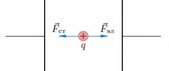
The diagram below shows a current-carrying loop that is energized and two magnetic poles that give it rotational motion.
The picture is clickable.
It is this pattern of interaction between the magnetic field and the current-carrying circuit with the creation of electromotive force that underlies the functioning of electric motors of all types. To create similar conditions, the device design includes:
- Rotor (winding) is a moving part of the machine, mounted on a core and rotation bearings. It plays the role of a current-conducting rotational circuit.
- The stator is a stationary element that creates a magnetic field that affects the electric charges of the rotor.
- Stator housing. Equipped with mounting sockets with cages for rotor bearings. The rotor is placed inside the stator.
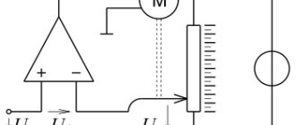
To represent the design of an electric motor, you can create a circuit diagram based on the previous illustration:
After connecting this device to the network, a current begins to flow through the rotor windings, which, under the influence of the magnetic field arising on the stator, gives the rotor rotation, which is transmitted to the rotating shaft. Rotation speed, power and other performance indicators depend on the design of the specific motor and the parameters of the electrical network.
Types of engines and their design
AC electric motors have a different design, thanks to which it is possible to create machines with the same rotor speed relative to the stator magnetic field, and machines where the rotor “lags behind” the rotating field. According to this principle, these motors are divided into corresponding types: synchronous and asynchronous.
Asynchronous
The design of an asynchronous electric motor is based on a couple of important functional parts:
- The stator is a cylindrical block made of steel sheets with grooves for laying conductive windings, the axes of which are located at an angle of 120˚ relative to each other. The poles of the windings go to the terminal box, where they are connected in different ways, depending on the required operating parameters of the electric motor.
- Rotor. In the design of asynchronous electric motors, two types of rotors are used:
- Short-circuited. So called because it is made from several aluminum or copper rods short-circuited using end rings. This design, which is a current-carrying rotor winding, is called a “squirrel cage” in electromechanics.
- Phase. On rotors of this type, a three-phase winding is installed, similar to the stator winding. Most often, the ends of its conductors go to the terminal pad, where they are connected in a star, and the free ends are connected to slip rings. The phase rotor allows you to use brushes to add an additional resistor to the winding circuit, which allows you to change the resistance to reduce inrush currents.
In addition to the described key elements of an asynchronous electric motor, its design also includes a fan for cooling the windings, a terminal box and a shaft that transmits the generated rotation to the working mechanisms of the equipment whose operation is provided by this motor.
The operation of asynchronous electric motors is based on the law of electromagnetic induction, which states that electromotive force can only arise under conditions of a difference in the speed of rotation of the rotor and the magnetic field of the stator. Thus, if these speeds were equal, the EMF could not appear, but the influence on the shaft of such “braking” factors as load and bearing friction always creates conditions sufficient for operation.
Synchronous
The design of synchronous AC electric motors is somewhat different from the design of asynchronous analogues. In these machines, the rotor rotates around its axis at a speed equal to the rotation speed of the stator's magnetic field. The rotor or armature of these devices is also equipped with windings, which are connected at one end to each other and at the other to a rotating collector. The contact pads on the commutator are mounted in such a way that at a certain point in time it is possible to supply power through the graphite brushes to only two opposite contacts.
Operating principle of synchronous electric motors:
- When the magnetic flux in the stator winding interacts with the rotor current, a torque arises.
- The direction of movement of the magnetic flux changes simultaneously with the direction of the alternating current, due to which the rotation of the output shaft is maintained in one direction.
- The desired rotation speed is adjusted by adjusting the input voltage. Most often, in high-speed equipment, such as rotary hammers and vacuum cleaners, this function is performed by a rheostat.
The most common reasons for failure of synchronous electric motors are:
- wear of the graphite brushes or weakening of the pressure spring;
- wear of shaft bearings;
- collector contamination (clean with sandpaper or alcohol).
Three Phase Alternator
Design features of a DC electric motor
Any electric motor consists of two main parts - a stator (frame) and a rotor (armature). As a rule, in modern 12 or 22 volt motors that are now common, the inside of the stator is covered with thin sheets of electrical steel, insulated with each other using a special varnish. They form separate poles and windings, ending with extensions in the form of tips, which contribute to the uniform distribution of electromagnetic induction in the air gap between the stator and rotor parts. Depending on the design and power of the electric motor, the winding may consist of numerous turns of thin wire or fewer turns of thicker wire.
The rotor is usually a cylinder mounted on a shaft with a gear structure. It is placed inside the stator, but located at some distance from it. The rotor is also made from thin steel sheets with insulation and ventilation gaps between the individual packages. The anchor grooves are connected by copper conductors. In addition, a prerequisite for the armature of a DC electric motor of the P or PL series is the presence of a two-layer winding.
Brushless DC motor. General information and device design
Motor controllers of this type are often powered by constant voltage, which is where they get their name. In English technical literature, a valve motor is called PMSM or BLDC.
The brushless motor was created primarily to optimize any DC motor in general. Very high demands were placed on the actuator of such a device (especially the high-speed microdrive with precise positioning).
This, perhaps, led to the use of such specific direct current devices, brushless three-phase motors, also called BLDC motors. In their design, they are almost identical to synchronous AC motors, where the rotation of the magnetic rotor occurs in a conventional laminated stator in the presence of three-phase windings, and the number of revolutions depends on the voltage and load of the stator. Based on certain coordinates of the rotor, different stator windings are switched.
stator windings serve as a fixing element
If one of the windings is turned off, the signal that was induced will be measured and further processed, however, this operating principle is impossible without a signal processing professor. But to reverse or brake such an electric motor, a bridge circuit is not needed - it will be enough to supply control pulses in reverse sequence to the stator windings.
In a VD (switched motor) an inductor in the form of a permanent magnet is located on the rotor, and the armature winding is on the stator. Based on the position of the rotor, the supply voltage for all windings of the electric motor is generated. When a collector is used in such designs, its function will be performed by a semiconductor switch in a switch motor.
The main difference between synchronous and valve motors is the self-synchronization of the latter using the DPR, which determines the proportional rotation speed of the rotor and the field.
Most often, brushless DC motors are used in the following areas:
- freezing or refrigeration equipment (compressors);
- electric drive;
- air heating, air conditioning or ventilation systems.
Stator
This device has a classic design and resembles the same device of an asynchronous machine. The composition includes a core of copper winding (laid around the perimeter in grooves), which determines the number of phases, and a housing. Usually the sine and cosine phases are sufficient for rotation and self-starting, however, the valve motor is often created as a three-phase or even four-phase one.
Electric motors with reverse electromotive force are divided into two types based on the type of winding on the stator winding:
- sinusoidal shape;
- trapezoidal shape.
In the corresponding types of motor, the electric phase current also changes according to the supply method, sinusoidally or trapezoidally.
Rotor
Ferrite magnets are considered the most common and cheapest for making a rotor, but their disadvantage is the low level of magnetic induction, so such materials are now being replaced by devices made from alloys of various rare earth elements, since they can provide a high level of magnetic induction, which, in turn, allows the rotor size to be reduced.
DPR
A rotor position sensor provides feedback. Based on the principle of operation, the device is divided into the following subtypes:
- inductive;
- photoelectric;
- Hall effect sensor.
The latter type has gained the greatest popularity due to its almost absolute inertia-free properties and the ability to get rid of delays in feedback channels based on the rotor position.
Control system
The control system consists of power switches, sometimes also of thyristors or power transistors, including an insulated gate, leading to a current inverter or voltage inverter assembly. The process of controlling these keys is most often implemented by using a microcontroller, which requires a huge number of computational operations to control the motor.
Electronics for everyone
After the previous post about the gear motor, I received several questions about regulating a DC motor. So it's time to write another post 
The direct current motor (DC motor) is one of the most familiar and understandable electric motors; it is studied even in school, in physics. It is used almost everywhere where a small-sized motor is needed, and is also in no hurry to lose its position even where power is measured in tens of kilowatts. Let's talk about him. ▌ Design and basic principle
I won’t go into too much detail here, I’ll show you a picture from Wikipedia and indicate a number of main components. Everything else you already know and have touched with your own hands.
1. The stator consists of a magnetic field source. This is not always a permanent magnet; moreover, a permanent magnet is the exception rather than the rule. Usually this is the excitation winding. At least on anything larger than a fist.
2. The armature consists of an armature winding and a collector unit.
Everything works very, very simply. The armature winding is repelled from the magnetic field of the stator by the Ampere force and makes half a revolution, trying to bring this force to zero and would have brought it out if not for the collector, which cleverly breaks off everyone, switches the polarity of the coil and the force again becomes maximum. And so on in a circle. Those. the collector serves as a mechanical voltage inverter in the armature. Remember this moment, it will be useful to us later
Usually in small motors there are only two poles of the field winding (one pair) and a three-prong armature. Three teeth is the minimum for starting from any position, but the more teeth, the more efficiently the winding is used, the lower the currents and the smoother the torque, since the force is a projection onto the angle, and the active section of the winding rotates to a smaller angle
▌Processes occurring in the engine
I think many of you who have dabbled with engines may have noticed that they have a pronounced starting current, when the motor at the start can jerk the ammeter needle, for example, to an ampere, and after acceleration the current drops to some 200 mA.
Why is this happening? This is how back emf works. When the engine is stopped, the current that can pass through it depends only on two parameters - the supply voltage and the resistance of the armature winding. So it’s easy to find out the maximum current that the engine can develop and for which the circuit should be calculated. It is enough to measure the resistance of the motor winding and divide the supply voltage by this value. Simply by Ohm's law. This will be the maximum starting current.
But as it accelerates, a funny thing begins: the armature winding moves across the magnetic field of the stator and an EMF is induced in it, like in a generator, but it is directed opposite to the one that rotates the engine. And as a result, the current through the armature decreases sharply, the more, the higher the speed.
And if the engine is further tightened along the way, then the back emf will be higher than the supply and the engine will begin to pump energy into the system, becoming a generator.
▌A few formulas
I won’t burden anyone with conclusions; you’ll find them yourself if you want. To make it less profane, I recommend finding a textbook on electric drives for secondary schools and an older year of publication. It’s from the 50s-60s. There are vintage pictures and painted for yesterday’s graduate of a rural seven-year school. Lots of letters and no sinkers, everything is clear and to the point.
The most important formula for a brushed DC motor is:
U = E + I*Rya
- U - voltage supplied to the armature
- Rya is the resistance of the anchor chain. Usually, only the resistance of the winding is considered as this symbol, although you can hang a resistor on the outside and it will be added to it. Then they write it as (Rа+Rд)
- Iya is the current in the armature circuit. The same one that is measured with an ammeter when trying to measure engine consumption
- E is the back emf or emf of the generator, in generator mode. It depends on the engine design, speed and is described by this simple formula
E = Ce * F * n
- Ce is one of the design constants. They depend on the design of the motor, the number of poles, the number of turns, and the thickness of the gaps between the armature and the stator. We don’t really need it; if desired, it can be calculated experimentally. The main thing is that it is constant and does not affect the shape of the curves
- F is the excitation flux. Those. stator magnetic field strength. In small motors, where it is set by a permanent magnet, this is also a constant. But sometimes a separate winding is brought out for excitation and then we can change it.
- n - armature revolutions.
Well, the dependence of torque on current and flow:
M = cm * Iа * F
Cm is a constructive constant.
Here it is worth noting that the dependence of torque on current is completely direct. Those. Simply by measuring the current, with a constant excitation flux, we can accurately determine the magnitude of the torque. This may be important, for example, in order not to break the drive, when the engine can develop such a force that it can easily break what it rotates there. Especially with a gearbox.
Well, it follows from this that the torque of a DC machine depends only on the ability of the source to supply it with current. So the ideal indestructible superconducting engine will tie you in knots, even if it’s as small as a nail. Just supply energy.
Now let’s mix it all together and get the dependence of revolutions on torque - a mechanical characteristic of the engine.
If you build it, it will be something like this:
n0 is the ideal idle speed of a spherical engine in a vacuum. Those. when our engine is finally freezing, the torque is zero. The current consumption is also, naturally, zero. Because back emf is equal to voltage. Purely theoretical option. And the second point is constructed with some moment on the shaft. It turns out there is a direct relationship between speed and torque. And the slope of the characteristic is determined by the resistance of the armature chain. If there are no additional resistors there, then this is called a natural characteristic.
Ideal idle speed depends on voltage and flow. Nothing else. And if the flux is constant (permanent magnet), then only from voltage. By reducing the voltage, our entire characteristic shifts down in parallel. Reduced the voltage by half - the speed dropped by half.
If it is possible to change the excitation flow, then you can raise the speed above the nominal one. Here the relationship is reversed. We weaken the flow - the engine accelerates, but either the torque drops, or it needs to consume more current.
Another engine with excitation removed may go into disarray. I remember I took a long course on electric drive, who knows how long after the session. I had to break it, yeah. Well, I sat in the laboratory, waiting for the teacher. And there were some dunces, a course lower, who made a lab. They turned the engine idle, and the excitation was attached to the stand on snot and flew off the terminal. The engine went haywire. In our laboratory at EPA SUSU, everything was serious, the machines were serious, ten kilowatts and about a hundred or so kg each. Everything is at a harsh voltage of 380 volts. In general, when this fool roared like a monster and began to tear itself from its mounts, all I had time to shout was to get the hell out of the car, turn it to hell. Before we had time, the engine was torn from its mounts, the windings flew out of the grooves and the engine suffered damage. Okay, no one was hurt. However, the drive labs were still entertainment. We had fires and explosions there. There I acquired remarkable skills to fix anything, with anything, in a short time. On average, everyone managed to completely kill the stand once, and the lab often began with repairing the soldering iron, which was used to repair the oscilloscope, with the help of which the dead stand was reanimated.
By adding resistors to the armature circuit we can increase the slope, i.e. The more we load, the more the speed drops.
The method is bad because the resistors in the armature circuit must be rated for the motor current, i.e. be powerful and will heat up in vain. Well, the moment drops sharply, which is bad.
There are also motors with sequential rather than independent excitation. This is when the stator winding is connected in series with the armature. Not every motor can be turned on this way; the field winding must withstand the armature current. But they have one interesting property. When starting, a large starting current occurs and this starting current is also the excitation current, providing a huge starting torque. The mechanical characteristic resembles a hyperbola with a maximum in the region of zero revolutions.
And then, as you accelerate, the torque drops, and the speed, on the contrary, increases. And if the load is removed from the shaft, the engine immediately goes into overdrive. Such engines are mainly installed on a draft drive. At least they did before, before the development of power electronics. This crap explodes from its place so much that all the street slayers nervously light up.
▌DC motor operating modes
The direction of rotation of the motor depends on the direction of the armature current or the direction of the excitation flow. So if you take a commutator motor and connect the excitation winding parallel to the armature, then it will rotate perfectly on alternating current (universal motors, they are often installed in kitchen appliances). Because the current will simultaneously change in both the armature and the excitation. The moment will indeed be pulsating, but these are minor things. And to reverse it, you will need to change the polarity of the armature or excitation.
If we draw a mechanical characteristic in four quadrants, we will have something similar to this:
For example, characteristic 1 in section I, our car works like an engine. The load increases and at a certain moment the engine stops and begins to rotate in the opposite direction, i.e. the load reverses it. This is a braking mode, anti-inhibition. The mode is very difficult, the engine heats up simply brutally, but it is very effective for braking. If the moment on the shaft changes direction and starts to rotate towards the engine, then the motor will immediately go into generation (section IV).
Characteristic 2 is the same, only with reverse polarity of the motor supply voltage.
And characteristic 3 is dynamic braking. It's rheostat. Those. when we take and simply short-circuit our motor to a resistor or to itself. You can check it yourself, take any motor and spin it, and then short-circuit its armature and spin it again. There will be a noticeable force on the shaft, the greater the quality of the engine.
By the way, motor drivers like the L293 or L297 have the ability to turn on rheostatic braking by turning both keys up or down. In this case, the armature shorts through the driver to the ground or power bus.
▌Brushless DC Motors
The collector engine is very good. It's damn easy and flexible to adjust. You can increase the speed, lower it, the mechanical characteristics are tough, it holds the torque with a bang. The dependence is direct. Well, it's a fairy tale, not a motor. If it weren't for one spoonful of shit in all this deliciousness - a collector.
This is a complex, expensive and very unreliable unit. It sparks, creates interference, and becomes clogged with conductive dust from the brushes. And under heavy load it can blaze, forming a circular fire, and then that’s it, the engine is screwed. It will short-circuit everything tightly.
But what is a collector anyway? Why is he needed? Above I said that the collector is a mechanical inverter. Its task is to switch the armature voltage back and forth, exposing the winding to the flow.
But it’s already the 21st century and cheap and powerful semiconductors are now at every turn. So why do we need a mechanical inverter if we can make it electronic? That's right, there's no need! So we take and replace the collector with power switches, and also add rotor position sensors so that we know at what moment to switch the windings.
And for greater convenience, we turn the engine inside out - it’s much easier to rotate a magnet or a simple excitation winding than an armature with all this junk on board. The rotor here is either a powerful permanent magnet or a winding powered by slip rings. Which, although it looks like a collector, is far more reliable than it.
And what do we get? Right! Brushless DC motor aka BLDC. All the same cute and convenient characteristics of the DPT, but without this nasty collector. And do not confuse BLDC with synchronous motors. These are completely different machines and have different principles of operation and control, although structurally they are VERY similar and the same synchronizer can easily work as a BLDC, adding only sensors and a control system. But that's a completely different story.
Symbols for DC motors of the P series.
P X1 X2 X3 M P – DC machine; X1 – version according to the degree of protection and cooling method. Without a letter - splash-proof with self-ventilation size 1-6. B – closed version with natural cooling, size 1-4; X2 – dimensions of the electric machine. 1-1 dimensions, 2-2 dimensions, 3-3 dimensions, 4-4 dimensions, 5-5 dimensions, 6-6 dimensions; X3 – nominal length of the armature core. 1 – first length, 2 – second length; M – marine version;
According to the installation method, DC electric motors have a design - IM1001, IM2101, IM2111, IM2131, IM3601, IM3631, IM3611. DC motors can be manufactured with an attached tachogenerator.
Operating conditions for DC electric motors P51, P52.
- DC motors P51, P52 are manufactured for operation at ambient temperatures from -40°C to +40°C.
- At an ambient temperature of 20° ± 5°C% relative humidity 95°±3°C%.
- Withstands vibration, shock, long-term tilting of the axis of a DC electric motor from 45° in any direction and when rolling up to 45° with a rolling period of 7-9 s.
Excitation of a DC motor is serial, parallel, mixed, independent. The heat resistance class of DC electric motor insulation is N. The general level of vibration of electric motors and the level of airborne noise intensity comply with all accepted standards.
Overall and connecting dimensions of DC motors P51, P52, PB51, PB52
| Type of DC motors | Dimensions, mm | Weight, kg for IM2101, IM2102, IM3601, IM2103, IM2104, IM3611, IM3631 | Weight, kg for IM1001, IM1004 | ||||||
| b10 | d1 | d20 | d30 | l10 | l30 | h | |||
| P51U4 | 264 | 35 | 255 | 352 | 225 | 606 | 180 | 122 | 115 |
| PB51U2 | 638 | 127 | 120 | ||||||
| P52U4 | 264 | 35 | 255 | 352 | 265 | 646 | 180 | 142 | 135 |
| PB52U2 | 678 | 147 | 140 |
Main technical characteristics of DC motors P51, P52
| Type | power, kWt | Voltage V | Mains current A | Rotation speed, rpm | Efficiency % |
| P51M | 2,7 | 110 | 33 | 750/1500 | 71 |
| 2,7 | 220 | 17,2 | 750/1500 | 74 | |
| 4,2 | 110 | 52,2 | 1000/2000 | 73 | |
| 4,2 | 220 | 25,6 | 1000/2000 | 74,5 | |
| 7,4 | 110 | 83,6 | 1500/2250 | 79,5 | |
| 7,4 | 220 | 41,8 | 1500/2250 | 80 | |
| 14,5 | 110 | 153 | 3000/3300 | 85 | |
| 14,5 | 220 | 77,3 | 3000/3300 | 85 | |
| P52M | 3,4 | 220 | 20,8 | 750/1500 | 74,5 |
| 5 | 110 | 58,5 | 1000/2000 | 77 | |
| 5 | 220 | 29,2 | 1000/2000 | 77 | |
| 8,8 | 110 | 97,8 | 1500/2250 | 81,5 | |
| 8,8 | 220 | 48 | 1500/2250 | 82,5 | |
| 16 | 220 | 84,5 | 2800 | 86 | |
| 20 | 220 | 104 | 3000/3300 | 87 |
DC electric motors of the P series 1, 2, 3, 4 dimensionsDC electric motors of the P51, P52 seriesDC electric motors of the P61, P62 seriesDC motors of the 2P series (2PO132 - 2PO200, 2PF132 - 2PF200)DC electric motors 2PN, 2PBElectric DC machines of the 4PD series DC motors current DP-112, DK-112, DKU-112MR permanent magnet motors
MTA motors on permanent magnetsPI, PC, 3PI motors on permanent magnetsMX, MVN, MVO motors on permanent magnetsDC electric motors of the DE seriesDC electric motors DPMEDC electric motors DPURDC electric motors PBS, PBSTDC electric motors DK-309M