The controlled circuit is not electrically connected in any way to the control circuit; moreover, in the controlled circuit the current value can be much greater than in the control circuit. That is, relays, in essence, perform the function of an amplifier of current, voltage and power in an electrical circuit.
AC relays operate when a current of a certain frequency of 50 Hz is applied to their windings, that is, the main source of energy is the AC network. The design of an AC relay is similar to that of a DC relay, except that the core and armature are made from electrical steel sheets to reduce hysteresis and eddy current losses.
A typical practice for using powerful electromagnetic relays is switching loads on alternating current 220 V 50 Hz or on direct current from 5 to 24 V with switching currents up to 10–16 A.
Common loads for power relay contact groups are heaters, low-power electric motors (for example, fans and servos), incandescent lamps, electromagnets and other active, inductive and capacitive current consumers.
Selecting an electromagnetic relay
Operating voltages and currents in the relay winding must be within the permissible values:
— reduction of operating current in the winding
leads to a decrease in the reliability of the contact group closure;
— an increase in the operating current in the winding leads to overheating of the winding, reducing the reliability of the relay at elevated temperatures.
Rice.
2. Appearance of the electromagnetic relay
Attention. Even a short-term supply of increased operating voltage to the relay winding is undesirable, since this causes mechanical overvoltages in the parts of the magnetic circuit and contact groups, and an electrical overvoltage of the winding when its circuit is opened can cause an insulation breakdown.
When selecting the operating mode
relay contacts must take into account the value and type of switched current, the nature of the load, the total number, switching life (switching on) and switching frequency.
When switching loads, the most difficult thing for contacts is the process of opening the circuit, since due to the formation of an arc discharge, wear of the contacts occurs.
Setting up and setting up contacts
when operating electromagnetic relays
The most important element of all electromagnetic relays is the contact system
. It is almost impossible to provide the same conditions for the passage of current at the point of electrical contact as a solid conductor has. Therefore, contact connections are the weakest point of any electrical device and require special attention during operation.
The magnitude of the contact resistance depends on the material of the contact connection, on the pressure experienced by the contact elements, on the surface area of their contact and its condition, and on the contact temperature. The current passing through the contact elements heats them. Excessive heating of the contacts leads to their oxidation and increases the value of the contact resistance.
The reliability of relay operation largely depends on the quality of the contact system adjustment and on the condition of the contacts. If the relay contacts vibrate, then during operation they burn and break, and sometimes become welded.
The operation of the relay contacts is characterized by:
— values of the solution between the moving and fixed contacts;
— failure of contacts;
— the force of compression (pressing, pressing) of the contacts.
A contact connection is characterized by a certain force value, above which the value of the contact resistance practically does not change.
Definition.
The contact opening is the smallest distance between the contact surfaces of completely open relay contacts.
Contact drop [mm]
is the distance by which the movable contact system of the relay moves after touching the contacts (the distance by which the contact system moves if the fixed contact system is mentally removed).
This is a certified technical value that provides pressing force. During operation, the contact wears out (friction, burnout of part of the contact due to an electric arc), and the contact pressure decreases. This means that the contact resistance increases and the risk of welding increases. Therefore, contact failure during operation is monitored.
The opening and failure of the relay contacts are determined using a measuring tool
. The measured values of openings, dips and clicks for each relay should not differ significantly from the corresponding values given in the technical data sheets of the relay.
Note. It is acceptable to reduce contact failure by 50% from the initial value given in the manufacturer’s documentation.
Clear and reliable operation of relay contacts without sparking, welding, melting and jumping depends on both their mechanical adjustment and the electrical adjustment of the relay as a whole. Therefore, the contacts are finally adjusted by flow after adjusting the electrical parameters of the relay, having previously performed mechanical adjustment of the contacts.
Before adjustment, dirty burnt contacts are washed with alcohol or cleaned with a velvet file and polished.
Advice. It is not recommended to wash contacts with gasoline, ammonia or other cleaning agents.
Contact relays are adjusted in such a way that there is no vibration or jumping of the moving contacts onto the fixed ones, and when straightening the fixed contacts with tweezers, breaks in the contact springs are avoided. The deflection of the springs of the fixed contacts depends on their elasticity, the angle of meeting and the joint stroke of the contacts, as well as on their pre-tension created by limiting stops and anti-vibration plates.
The cause of unacceptably strong vibration of the contacts may be mechanical malfunctions of the relay that do not appear at low currents. Usually the cause of vibration is the incorrect position of the bridge on the axis relative to the armature or the misalignment of the armature axis relative to the axis of the magnetic flux due to misalignment of the holes for the thrust bearings.
In the first case, large longitudinal and transverse gaps are eliminated, the return spring of the contact bridge is replaced, and distortions in the axis of the contact bridge or the magnetic system of the relay are eliminated. In other cases, mechanical adjustment of the contacts is also carried out.
Reducing and eliminating arcing of
electromagnetic relay
An electric arc rarely appears on low-power electromagnetic relay contacts, but often occurs sincerely.
When a circuit with inductance is quickly turned off, a significant emf L (di/dt) arises, which can exceed the breakdown voltage of the insulating gap between the contacts. This is especially dangerous in sensitive and high-speed electromagnetic relays, in which the contact opening is made very small.
Sparking increases when the relay contacts vibrate. It shortens the service life of electromagnetic relay contacts and can lead to false operations of high-speed control circuit devices or breakdown of semiconductor elements due to overvoltage.
To reduce sparking of relay contacts, special circuits are used that create an additional electrical circuit through which the current caused by the self-inductive emf is closed. The electrical energy stored in the inductance of the switched circuit is released as heat in the resistors of the spark-extinguishing circuit, thereby reducing the sparking energy.
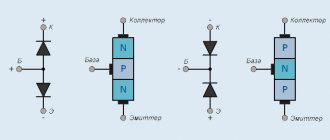
When using direct current, the load is shunted with a diode ( Fig. 3, a
). At the moment the relay contacts open, a transient current occurs and energy is released on the active component of the load resistance.
Rice.
3. Spark extinguishing circuits : a - diode shunting;
b - bypassing the relay contacts with the RshSsh chain When bridging the relay contacts with the RshSsh chain (Fig. 3, b
) the magnetic field energy is released not only at the load, but also at the resistor Rsh. The capacitance value Csh in this circuit is 0.5–2 μF and is finally selected when setting up the circuit.
Resistance Rsh is determined using empirical formulas. For silver contacts Rш=Uc2/140, where Uc is the voltage drop across the capacitor. The resistance value Rsh in low-current electromagnetic relay circuits is 100–500 Ohms.
All spark extinguishing circuits worsen the dynamic parameters of electromagnetic relays, increasing the time they turn on or off.
Reed switch operation
A simple relay with closure contacts consists of two cores with contacts having increased magnetic permeability. They are located in a sealed glass container with an inert gas or a mixture of gases. A pressure of 50 kPa is created in the cylinder. The inert environment prevents contacts from oxidizing. The reed switch cylinder is placed inside the control winding connected to direct current. When the power is turned on, a magnetic field is formed on the relay, passing through the contact cores, along the gap and closes through the control coil. Magnetic flux creates a traction force that connects the contacts to each other.
To keep the contact resistance to a minimum, the touching surfaces are coated with silver, radium, palladium, etc. When the power is turned off in the reed switch electromagnet coil, the force disappears and the springs open the contacts. In reed relays there are no friction surfaces of parts; the contacts have many functions, performing the work of a magnetic circuit, conductor and spring. To reduce the size of the magnet coil, the current density is increased. Use enamel wire to wind the coil. Reed switch parts are stamped, connections are made by soldering or welding. Reed switches use magnetic shields to reduce the activation zone.
Reed relay.
The springs in reed relays are installed without additional tension; they turn on immediately, without wasting time on starting. Instead of an electromagnet, permanent magnets can also be used. Such reed switches are called polarized. The pressing force of the contacts of a reed relay is determined by the magnetic force of the coil, in contrast to conventional electromagnetic relays, in which the force depends on springs. When opening, the reed switch works differently.
The system of relay magnets, under the action of electromagnetic force, magnetizes the cores of the same name, which repel each other and open the circuit. In a reed switch with switching, one of the 3 contacts is closed and made of non-magnetic metal. The remaining two contacts are made of ferromagnetic composition. Under the influence of a magnetic field, open contacts close, and closed non-magnetic contacts open. Although there is always a magnetic field, like the Earth’s field, such a field is not enough to trigger the reed switch, so it is neglected.
Design differences
The multifunctional reed switch is presented in the form of a sealed glass container, inside of which sensitive contacts are located. These elements are magnetic cores welded to the end sides of the product. All external parts are connected to the existing electrical network.
The most popular today are reed switch relays for short circuits. The contacts are made of high-quality rectangular ferromagnetic wire. The cores are made from permalloy - a material where the main role is played by power, as well as the size of the reed switch. If necessary, the coating can be replaced with silver, gold, or rhodium.
The finished flask is evacuated or an inert gas is introduced into it, which prevents the development of corrosion in the switch. During the manufacturing process, specialists also take into account the fact that there is a gap of a certain diameter between the cores.
Application of reed switches
Reed sensors and switches use:
- medical devices and communication devices;
- apparatus for submariners;
- synthesizers and keyboards;
- testing instruments, meters;
- automation and safety devices.
In security systems, sensors on reed switches are used as relays. The security sensor includes a magnet and a reed switch. The simplest reed relay consists of a winding and a reed switch. Comparative characteristics of reed switches and other types of relays are presented in the table below.
Comparison of reed relays with other types according to their main characteristics.
Material on the topic: What is a condenser
The advantages of reed switch relays include:
- small dimensions, simple device;
- protection from moisture, burning of the contact group;
- no rubbing parts.
Reed relay device
Such reed switch sensors are widely used, but they also have disadvantages, such as susceptibility to mechanical damage. This is a big disadvantage for use in many systems. Reed switches are indispensable in alarm systems. Installing the sensor is not difficult. When the door is closed, the reed switch contact is closed. When the door is opened, the magnet attached to the jamb moves away from the reed switch, the magnetic force decreases, and the power circuit opens.
This serves as a signal to trigger the alarm circuit. The situation is similar with the use of reed switches in elevators. Reed switches are used to determine the location of the elevator car. Using magnets and a reed switch, it is easy to control lighting equipment. Electricity meters also have reed switches.
Short description
In the modern world, reed switches are practically not used, since more universal Hall sensors have gone on mass sale. But there are still situations when you simply cannot do without such a relay. The whole point is that the device is easy to control and can be installed in the circuit of any equipment. When a master needs to achieve a high degree of reliability and durability from a unit, then he simply cannot do without a reed switch.
Today such a relay can be found in various sensors and similar devices. Functionality is usually divided into three main categories:
- Switching.
- Closure.
- Opening.
Among the main technical features are dry and mercury contact. In the latter case, the glass case contains drops of metal, which are especially important during the operation of the relay, as the quality of contact improves.
In addition, mercury helps to avoid unwanted vibration, thereby increasing the response time of the installation. This is why experts always recommend using this type of contact.
Tips for use
When using reed relays or sensors, you can give several tips that take into account the nuances of using such devices:
- When installing reed switches, avoid sources of ultrasound if possible; it can negatively affect the electrical parameters of the sensor and change them.
- A nearby magnetic field source can also change the characteristics and properties of the magnetic switch.
- Reed relays and sensors are resistant to shock and mechanical damage. Inert gas inside the sensor may escape upon impact due to a leak in the gas tank. This will disable the reed switch.
- When performing soldering, you must follow the instructions of the manufacturer of the reed switch sensor.
Soviet reed relays.
Types of models
High-quality reed relays are usually divided into several categories, which differ in the design of the contact group. Each variety has numerous positive characteristics that are highly valued by both specialists and home craftsmen. There are several types of reed switches on sale:
- With switching contact type.
- Traditional open-loop installations.
- Specific elements with closed contacts.
In addition to the main functional characteristics, experts also highlight technological parameters that divide sealed switching units into dry and mercury.
Gersikons
Relays on reed switches have a wide variation in the return coefficient due to manufacturing technology errors. To increase the rated power and switching current, auxiliary contacts are built into reed relays to extinguish the arc. Such relays are called gersikons, or power sealed contacts. Industrial production produces hersicones for currents up to 180 amperes. Their switching frequency reaches up to 1200 switchings per hour. Gersikons are used to start asynchronous electric motors with a rated power of up to 3000 W.
It will be interesting➡ What is a solid state relay?
SECURITY ALARM DIAGRAM
CONNECTING WITH YOUR OWN HANDS
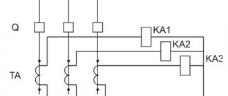
First, let's look at the general diagram of security alarm connections. It is shown in Fig. 1 and includes:
- receiving and control device - PKP;
- detectors (sensors) - IO;
- sound and light warning devices - OP;
- power supply - PSU.
Certain control panel models have a built-in power supply with the ability to connect detectors. For a small number of sensors, power is sufficient. In the receiving diagram of the control device, these points are designated as the output “plus” and “minus” or “common” voltage of 12 Volts.
Please note that the control panel is the central part of the alarm system, which, in fact, is determined by the purpose and operating principle of the system.
The given example illustrates the interconnection of security system equipment; specific connection diagrams for technical equipment are given in the documentation of the manufacturers. However, different types of sensors and devices have a lot in common, so you can connect them to each other without using special instructions and descriptions.
Ferrite Reed Relays
This is a special class of reed relays with ferrite cores. They have a memory function. To make a switch in reed switches of this type, you need to apply a current pulse of reverse polarity in order to demagnetize the ferrite core. They are called memory hermetic contacts, or gelawns. Advantages of reed relays:
- The absolute tightness of the contacts makes it possible to use them in aggressive environments, under conditions of dust, humidity, etc.
- Small dimensions, light weight, simple design of the sensor.
- The increased operating speed makes it possible to use reed switches at high switching frequencies.
- Reliable operation in a wide temperature range (from -60 to +120 degrees).
- Wide range of applications combined with relay functionality.
- Availability of galvanic isolation of switching circuits and relay controllability on reed switches.
- Increased strength of electrical contacts.
- Long sensor life.
Disadvantages of reed switches:
- Low sensitivity of reed switch magnets.
- Excessive sensitivity of the sensor device to magnetic fields. This requires protective measures against magnetic forces.
- The reed switch cylinder is made of fragile material, sensitive to damage and shock.
- The switching power is small for both gersikons and reed switches.
- At high currents, the reed contacts open spontaneously.
- When operating on low-frequency voltage, the contacts open and close without control.
Reed relay in the diagram.
Reed switch is an ultra-precise, high-speed sealed switch controlled by a magnetic field. The number of its operations is up to five billion times. Based on it, magnetic field sensors and reed relays are produced for a wide variety of applications - from household appliances to aviation and astronautics. The article describes the features of choosing reed switches and provides a tabular overview of the wide range of these products produced by Littelfuse. The word "reed switch" is an abbreviation of the words "sealed contact". The first reed switch was developed in 1936 by the American company Bell Telephone Laboratories. Subsequently, they became widely used as sensors, and reed relays were created on their basis.
It will be interesting➡ Features of an electromagnetic relay
The reed switch consists of two ferromagnetic conductors having flat contacts, sealed in a glass capsule. Without an external magnetic field, the contacts are open and there is a small dielectric gap between them. In a magnetic field, the contacts close. The contact area of both plates has a sputtered or galvanized coating made of a metal that is very resistant to erosion (usually rhodium, iridium or ruthenium). The structure of contact coating layers is shown in Fig. 2a and 2b for rhodium and iridium, respectively.
Iridium, ruthenium and rhodium are very resistant to erosion platinum group metals. Thanks to the deposition of these metals, the number of contact activations reaches five billion times. Nitrogen is usually pumped into the capsule cavity. Some types of reed switches are evacuated to increase the maximum permissible switching voltage. The reed switch contacts in a magnetic field are magnetized, and a magnetomotive force equal to the magnetic field strength arises between them. If the magnetic field strength is high enough to overcome the elastic forces in the contacts that arise during their elastic deformation, then the contacts close. When the field weakens, the contacts open again.
Relay connection.
There are two types of reed switches: SPST-NO (Single Pole, Single Throw Normally Open, that is, “one pole, one channel”) - a regular switch in which two contacts are normally open; SPDT-CO (Single Pole, Double Through Change Over, that is, “one pole, two channels - switching”) is a switch in which one contact is always normally closed and the second is normally open. The common plate is the only moving part of such a reed switch; in the absence of a magnetic field, it is closed with a normally closed relay contact. When a magnetic field of appropriate strength occurs, the common plate closes with a normally open contact. Both plates of the normally open and normally closed contacts are stationary.
The open contacts have a ferromagnetic coating, and the normally closed contact is made of non-magnetic material. When placed in a magnetic field, the moving contact and the normally open contact are magnetized in the same direction, and with sufficient magnetic field strength, the moving contact closes with the stationary ferromagnetic contact. When the external magnetic field disappears, the magnetization of the contacts weakens and they open. To ensure that the residual magnetization is minimal, high-temperature processing of the contacts is used in the manufacture of reed switches. A permanent magnet (Fig. 5) or a solenoid is most often used as a source of magnetic field for a reed switch.
Device characteristics
A high quality reed switch consists of two contacts that are made of a specific ferromagnetic alloy. They are installed in a durable flask, so the user can always control their operation. If a permanent magnet is supplied to the contacts, then a short circuit occurs, forming a continuous circuit. Because of this specificity, the reed switch began to be called a limit switch.
Industrial manufacturers label such units in strict accordance with the final scope of application. For example: if the abbreviation KEM is marked on the relay, then it belongs to the category of switching electrical mechanisms. A large letter “A” means that the device can be used in any weather conditions, but parts marked “B” are intended exclusively for indoor use. You will often see the abbreviation MKA, which means that this magnetic switch is ideal for any application.
For a standard switching unit, the resistance level is within 0.2 ohms. A high-quality reed switch for opening is distinguished by the fact that this indicator is 1 kOhm. Such data allows technicians to significantly speed up the switching of existing circuits. All magnetic switches of this type are used for power voltage networks, as they have higher performance. The magnetic trip reed switch is actively used in various circuits, in the computer and security industries, as well as contact sensors.
Operating principle of a reed relay
The operation of a normally closed reed switch uses the principle of interaction of forces arising between magnetic bodies. In the electromagnetic field, impulses appear and are transmitted, electrons begin to move, causing movement and deformation of current-carrying contacts. Changing the position and state of the magnetic limit switch in a specific device or circuit leads to the opening of the contacts. Further changes in their position occur under the influence of other moving elements - buttons, end springs, disks, etc. Thus, the contacts are switched on and off alternately.
It will be interesting➡ Current relay: what is it and what is it used for?
This operating principle became the basis for the functioning of an intermediate reed relay that acts on a short circuit. Its design consists of two cores and a sealed durable glass cylinder filled with gas or a gas mixture. The cylinder itself is under constant action of electric current. The gases prevent the oxidation of the metal cores.
When a DC reed switch is connected to such a reed switch, a powerful magnetic field is formed around the cores. The presence of special gaps greatly facilitates the passage of this field between the parts of the relay. Next comes the emergence of an autonomous magnetic flux moving in a given direction. The joining of the cores is greatly accelerated by coating them with precious metals with lower resistance than conventional material. A constant magnetic flux is ensured by the design features of the reed relay.
The uniformity and integrity of parts is created through casting and stamping, and welding processes are used to connect them together. Therefore, the relay coil is magnetized to a minimum extent. A reed switch relay works according to this scheme, the principle of operation of which is quite simple. If the DC supply is interrupted, the contacts will open and the magnetic flux will disappear.
Related material: How to connect a capacitor
Coils of electrical devices
Definition and classification
Definition.
A coil is a winding of insulated wire, wound on a frame or without a frame, and having terminals for connection.
The frame for the inductor is made of a dielectric material, for example, cardboard or plastic. Coils are used to create magnetic flux, which creates driving forces for the operation of devices or inductive reactance when the coil is a choke.
Coils can be divided into:
- current, containing a small number of turns of wire with a cross-sectional area corresponding to the strength of the passing current;
- voltages containing a large number of turns of small cross-section wire.
Coils are used
in electromagnets, contactors, starters and relays, releases of circuit breakers, electric brakes, in electrical measuring instruments, in starting and control devices of fluorescent lamps as chokes, in power supplies for automation and radio electronics equipment also in the form of chokes.
Coil insulation is subject to overvoltage
- voltage surges when the circuit of its winding is broken, depending on the speed of opening the circuit, the number of turns of its winding, and the magnetic system of the device. These overvoltages can be transmitted to other relays, causing them to operate falsely.
Overvoltages can also be transmitted from an external circuit when the coils of other devices are turned on.
Coils of the same sizes can be manufactured for different voltages - alternating 36, 110, 220, 380, 660 V and constant 6, 12, 24, 36, 48,
60, 110, 220, 440 V.
Note. The coils of new devices must be checked to ensure that the voltage for which they are manufactured corresponds to the mains voltage. This can be done by looking at the label on the overall insulation of the coil winding.
The same must be done when replacing a failed coil. If there is no label on the surface of the coil, then you can measure its resistance and compare it with the same coil of another device.
When setting up a new device or replacing a coil
Before installing it in place, you need to check whether the moving parts of the electromagnet are touching the insulation of the coil, and if they are, then you need to place it so that there is no contact, or adjust the movement of the moving parts, and only then strengthen the coil.
It is necessary to ensure that there is no air gap when touching the armature and the core of the electromagnet, since in the presence of an air gap the inductive resistance of the winding decreases, the current increases, and the coil can overheat and fail.
When connecting a DC coil
Polarity must be observed when a device, for example a polarizing relay, reacts to the direction of the current.
Combating coil overheating
Coil overheating
leads to an increase in the active resistance of the wire, a decrease in current and the force attracting the electromagnet core. Overheating can cause cracking of the insulation, false operation of the relay, an increase in the air gap between the armature core and even greater overheating of the coil, burning of the insulation of its winding.
Advice. It is necessary to ensure that the coils do not heat up from extraneous heat sources, for example, from resistors installed nearby and especially below the coil.
A high coil temperature can be caused by an increased temperature in the room where the equipment is installed, a high temperature in the control cabinet due to heat generation from the devices, or overheating of the device on which the coil is installed. Overheating of the device coil can also occur when it is frequently turned on and off when the conditions of air exchange and ventilation of the equipment in the room or power cabinet are violated.
High coil temperature also reduces the insulation resistance of the winding wire. At high temperatures, wire breaks are possible due to different thermal expansion of the wire and the coil frame. High temperatures accelerate the aging process of the coil insulation.
Moisture can penetrate the coil through the overall insulation, the insulation between layers to the wire and help reduce the insulation resistance of the wire. This can cause short circuits between winding layers or between turns within a layer. As a result of a short circuit, burnout/burnout of the winding and interturn short circuits may occur, which will lead to irreversible damage to the winding. or shunting part of the turns, which will contribute to overheating of the coil.
At low temperatures, moisture can freeze in the coil and cause it to fail.
As a result of the influences on the coil discussed above, there may be a disturbance in the current circuit in the coil due to a broken wire inside the coil, broken leads, oxidation of the output terminals, burning of the insulation of part of the turns, or complete burning of the winding insulation.
Replacing the coil
When checking a coil after a failure, complete combustion of its insulation is immediately visible, since the outer insulation of the coil usually burns out
.
If the outer insulation is not burned, but the coil does not work, then by bending the outer insulation, you can see the burnt insulation of the wire. Checking the coil wire for a break
can be done using a voltage indicator, ohmmeter or megohmmeter.
When checking the coil using a voltage indicator
if the winding is working properly and there is voltage at one terminal of the coil, it should also be at the other terminal. This last pin must be disconnected from the network (power supply, circuit) to eliminate measurement errors.
An ohmmeter connected to the coil terminals, if the coil is in good condition, will show its resistance according to the passport, and if there is a short circuit of the turns, it will show less resistance, but if the short circuit of the turns occurs only under the influence of voltage, then the ohmmeter may not show a change in resistance.
A megohmmeter, if the coil is in good condition, will show the resistance of its winding when measured in kiloohms to be a little more than 0, but less than 1 kOhm, and when measured in megaohms - 0, since the coil resistance is measured in ohms.
Purpose and scope
Reed sensors, despite being replaced by Hall sensors, still find application in many devices and systems:
- Keyboards for synthesizers and industrial equipment. The design of the sensors eliminates the possibility of sparks. Therefore, they are primarily used in explosive production areas where flammable vapors or dust are present.
- Household meters.
- Automatic security and position control systems.
- Equipment operating under water or in high humidity conditions.
- Telecommunication systems.
- Medical equipment.
Security systems use devices consisting of a reed switch and a magnet. They report the opening or closing of doors. Reed relays are also used, consisting of a contact sensor and a wire winding. This system has some advantages: simplicity, compactness, moisture resistance, absence of moving parts. Reed switches are also used in special areas - these are mechanisms for protecting against overloads and short circuits of high-voltage and radio electrical installations. These are also high-power radars, lasers, radio transmitters and other equipment operating under voltage up to 100 kV.
Various reed relays.
Literature
1. https://www.meder.com/
2. Meder Electronics, Reed Relay in Comparison with Solid-State and Mechanical Relays, p.82
3. Meder Electronics, Instrumentation Grade Reed Relays, 03/2010
4. Meder Electronics, Reed Switch Operational Characteristics pp19-21
5. Meder Electronics, Reed Switch Used as a Reed Relay, p.64
6. Meder Electronics, Reed Switch Characteristics pp27-32.
Obtaining technical information, ordering samples, delivery - e-mail
ATUM Series Heat Shrink Tubing from TE Connectivity
Raychem , part of TE Connectivity, has gained worldwide recognition as the founder of cross-linking technology in polymer materials. These bonds are formed during radiation exposure of materials, giving them a “shape memory” effect. The shape of such a material, changed at high temperature, is retained upon subsequent cooling. Then, when reheated, the cross-links cause the material to return to its original shape. This property of cross-linked polymer materials (thermoelastics) is used for the production of heat-shrinkable tubes. Heat-shrinkable tubing produced by TE Connectivity satisfies almost all consumer requirements:
- effectively cover the junctions of cables and individual wires with connectors,
- tie the wires into bundles,
- cover the junctions of wires, protecting them from corrosion,
- isolate components included in the line break from short circuits and moisture.
the ATUM series are available for order at the COMPEL warehouse
ATUM series tubes are available in two modifications - with a shrinkage ratio of 3:1 and 4:1. This coefficient allows them to be used for sealing cable connections with connectors. The tubes tightly surround the components and protect them from short circuits. A special feature of the series is the presence of an internal adhesive layer that bonds to a wide range of plastics, rubbers and metals, including polyethylene, aluminum, steel and copper. ATUM series tubes are used to protect the back side of connectors and cable connections from environmental influences. The high shrinkage coefficient allows you to repair damage to the cable sheath without removing the connector.
- Minimum shrinkage temperature 80°C,
- Full compression temperature 110°C,
- Operating temperature range from -55 to 110°C.
Black tubes are available to order, other colors are available on request.
•••
Symbol structure
RPG-9-ХХХХХХХ:
- RPG - intermediate reed relay;
- 9 — development number;
- X - type of fastening and connection of external wires (0 - screws, rear, soldering;
- 1 - plug connector, rear, soldering);
- X - type of reed switch: 5 -MKA-52202, 6 -MKS-52201;
- X - number of closing contacts (0-4; 6);
- X - number of breaking or switching contacts: 1 or 4;
- X - number of relays in one size (1; 2);
- XX - climatic version and placement category (U3, O4) according to GOST 15150-69.
terms of Use
- Altitude above sea level no more than 4300 m.
- The upper limit value of the ambient air temperature is 55C.
- At altitudes above 1000 m, the upper temperature value decreases by 0.6 C for every 100 m.
- Any working position in space.
- Type II atmosphere according to GOST 15150-69.
- Mechanical design group M7 in accordance with GOST 17516.1-90, operation of the relay is allowed when placed in places provided for groups M1, M2, M3, M4, M6 and M8 in accordance with GOST 17516.1-90.
- The degree of protection of the relay is IP30, the outputs are IP00 according to GOST 14255-69.
- The relays are designed for switching loads of application category DC-11, AC-11 in accordance with GOST 17523-85, DC-21, AC-21 in accordance with GOST 12434-93.
- Safety requirements comply with GOST 12.2.007.6-93.
- According to the method of protecting a person from electric shock, relays belong to class 0 according to GOST 12.2.007.0-75.
- Fire safety requirements according to GOST 12.1.004-91.
- Relays are manufactured for domestic and export deliveries and comply with TU 16-647.056-87.
DIY SECURITY ALARM
I would like to give advice to those who want to make a security alarm themselves. The times when it was profitable and expedient to assemble security circuits yourself from scrap materials and parts are gone forever. You can, of course, make a semblance of an alarm system with your own hands, but this will be a parody of a normal security system.
However, for those interested, I will give some explanations and provide a diagram by which you can assemble a simple security alarm. Since the principle of operation of any security system is to detect intrusion and notify about this fact, we will need:
- a closed electrical circuit that will be disrupted when attempting to enter (alarm loop - AL);
- violation recording device (receiving control device);
- a means of notifying an alarm situation (annunciator).
Please note that you can do everything from improvised means, or partially use the listed technical means. This way you can make your own security alarm for your dacha or home. A diagram of the simplest signaling using available means is shown in Figure 4.
Let's start with the terminals “+”, “-“. A power source is connected to them. I don’t know what you prefer, a battery, an AC adapter from some device, maybe a standard power supply - it doesn’t matter.
Based on its parameters, we select a relay with the required operating voltage. In addition, it must have two independent normally open contacts. It's minimum. The transistor must have parameters corresponding to the selected relay (operating collector current and voltage). The transmission coefficient is not important.
The resistor value is sufficient to fully open the transistor. It can lie within a fairly wide range (10-50 kOhm).
By the way, if you do not have basic knowledge of circuit design and skills in working with electrical components, then it will be easier to select a ready-made alarm kit based on the requirements for it.
As an AL, you can use a thin wire laid in such a way that an intruder will break it when trying to violate the protected area.
As long as the loop maintains its integrity, the transistor is closed. If it breaks, it opens, a relay is activated, which turns on the warning system with one pair of contacts, and blocks the transistor with the other. Now, even when the security loop is restored, the relay contacts will remain in a closed state until the voltage is removed from the circuit.
At its core, we have a latch trigger. Other circuit solutions are also possible, which you can come up with and implement yourself, knowing the basic principle of operation of the security alarm. In addition, standard (factory) detectors can be connected to a homemade alarm system. The combinations obtained in this way will be richer in their capabilities.
However, a simple security alarm has an undoubted disadvantage, namely the inconvenience of managing the arming/disarming process, as well as the lack of some other options inherent in professional alarm control devices.
Thus, the conclusion formulated at the beginning of the section suggests itself: even with your own hands, it is better to make a security alarm system for your home or cottage using special technical means.
Sealed magnetic contacts
Sealed magnetically controlled contacts Catalog-prospect M.: Central Research Institute "Electronics", 1973
Sealed magnetically controlled contacts (reed switches, MK) in most cases are two flat petals (contacts-parts) made of a soft magnetic alloy (for example, 52N-VI, 47 ND or others), hermetically welded into the opposite ends of a glass tube (balloon) in this way that their free ends overlap at a distance of 0.3 - 1.1 mm with a solution of 30 - 150 µm. The contacting surfaces are coated with noble metals or their alloys. The internal volume of the cylinder is filled with protective gas or evacuated. Under the influence of a magnetic field created by an electromagnetic control coil or a permanent magnet, the contact parts are magnetized and attracted to each other, completing the electrical circuit. When the control field decreases to a certain value f, the contacts - parts open under the influence of elastic forces. Reed switches are used to construct relays, logic elements, voltage and current converters, sensors of non-electrical quantities, coaxial switches, switches, actuators for frequency adjustment circuits in RF devices, toggle switches, limit switches, key switches, etc. Reed switches can be controlled by a magnetic field generated by a permanent magnet, an electromagnetic control coil, or a combination of both. To increase the service life of reed switches, various schemes for protecting contacts from electrical erosion are used, based on the use of LC elements, semiconductor diodes, semiconductor variable resistances (varistors) and silicon zener diodes. When developing a specific protection scheme, the meanings of the circuit elements should be practically clarified. Current and voltage surges must not exceed the maximum permissible values specified in the technical specifications or brochures for reed switches. It must be taken into account that the reactance of the cables (wires) connecting the reed switches to the loads also reduces the number of switchings. It is advisable to use protection circuits when operating reed switches on active loads - this allows you to significantly increase the number of switchings, since the destructive effect of the electric arc in the most dangerous opening mode for this type of load is reduced. 1. Application of reed switches 2. Methods of controlling reed switches 3. Methods of protecting reed switches 4. Technical data and images of reed switches Closing reed switch, asymmetric MK-10-3 Closing reed switch MK-16-3 Closing reed switch KEM-2 Closing reed switch MUK-1A-1 Reed switch closing, high-frequency MK-17 Reed switch, universal, changeover KEM-3 Reed switch, closing MK-27-3 Reed switch, closing, measuring MK-27-I Reed switch, universal, changeover MK-27-P Reed switch, closing KEM-6 Reed switch, closing KEM-1 Reed switch, closing MUK-3A-1 Reed switch closing, measuring MK-1 Reed switch closing, vacuum, high voltage MK-52-3V 5. Some schemes for using magnetically controlled contacts 6. Additions and edits Scans of the document were provided by Alexander Perebaskin (Moscow) creator of the portal >> Microcircuit Reference
CONNECTING THE SECURITY ALARM
Let's look at how to connect a security alarm using the most common types of equipment as an example.
Reception and control device.
This device must have terminals designated as “ШС” - alarm loop. Depending on its type, the polarity “+”, “-“ can be taken into account when connecting. This is necessary when using addressable devices or detectors that receive power via a loop. For conventional sensors this is not important.
In addition, the following are connected to the control panel:
- sirens,
- notification transmission systems (TSS) - monitoring station terminals.
When using GSM alarms, the last point is not relevant, since data transmission is carried out wirelessly by a module built into the device.
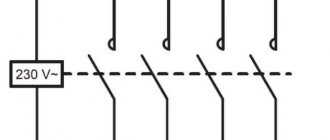
Alarm systems can be managed in several ways:
- “Dry” relay contacts (option A). In this case, additional supply voltage is required.
- “Open collector” outputs (version B). It looks like a relay option, but the polarity must be observed.
- Terminals specially designed for this purpose (case B). In this case, the voltage is supplied to them inside the device at the hardware level.
The described options are shown in Scheme 2.
Connecting security alarm sensors.
Most security sensors are energy-consuming devices. This means that there are at least 4 screw terminals on their terminal block. The exception is addressable detectors; they receive power via a loop and are connected via a two-wire line.
Note! In this case, observing polarity is mandatory.
Combined detectors have two independent sensors with independent outputs. Their connection can be done in two ways:
- into various security loops;
- to the common loop according to the “I” circuit.
The considered options for security alarm systems are illustrated with sensor connection diagrams in Fig. 3. Using this principle, motion sensors, vibration and acoustic detectors that have a relay output from a remote control pair can be connected.
Some detectors have a tamper sensor (tamper). It is designed to prevent the case from being opened during unprotected times and changes being made to the cable connection diagram. If it is necessary to prevent such a possibility, then the tamper is included in a separate loop that is constantly monitored.
The connection diagram in this case will be similar to a combined detector, where the tamper switch contacts will act as one of the AL outputs. Otherwise, you can disable this option and ignore the corresponding terminals.
To the begining