Purpose of substations A substation containing step-up transformers increases the electrical voltage with a corresponding decrease in current, while a step-down substation reduces the output voltage with a proportional increase in current.
The need to increase the transmitted voltage arises in order to significantly save the metal used in power transmission line wires and reduce losses on active resistance. Indeed, the required cross-sectional area of the wires is determined only by the strength of the passing current and the absence of a corona discharge. Also, a decrease in the strength of the passing current entails a decrease in energy loss, which is in direct quadratic dependence on the value of the current strength. On the other hand, to avoid high-voltage electrical breakdown, special measures are used: special insulators are used, wires are separated at a sufficient distance, etc. The main reason for increasing the voltage is that the higher the voltage, the greater the power and the greater the distance can be transmitted over power lines.
Installation of transformer substations and distribution devices
Installation technology of complete switchgears (Switchgear) for indoor installation Switchgears are installed only in premises where all construction work has been completed. Installation structures for switchgear are made of angles or channels, which are installed horizontally, aligned with level. Unevenness is allowed 1 mm per 1 m length and 5 mm along the entire length. According to the PUE, these structures are connected to the grounding loop with strip steel 40 x 4 mm in at least two places. When installing switchgear cabinets indoors, the width of the passage for a single-row installation must be equal to the length of the roll-out trolley plus 0.8 m, for a double-row installation - the length of one trolley plus 1 m. The distance from the cabinets to the side walls is at least 0.1 m. Installation of KSO and switchgear cabinets start from the outermost chamber. Check that the camera is installed correctly horizontally and vertically, only then install the next camera. Upon completion of installation, the camera bodies are connected with bolts, starting from the outer chamber. Tighten the bottom bolts first, then the top ones. Using a cord, check the straightness of the top of the chambers and, if necessary, adjust their position using steel pads. By rolling in the cart, check that the switchgear cabinets are installed correctly. The moving parts of the cart and the stationary parts of the cabinet must match, and the position of the cart must be securely fixed. They especially carefully check the operation of the curtains, which must be lowered and raised without distortions or jamming, as well as the operation of the mechanical lock. The verified switchgear cabinets and KSO chambers are finally secured by electric welding to the installation structure in the four corners. This also ensures reliable grounding of cabinets and chambers. Next, install the busbars, observing the colors of the phases. To do this, it is necessary to remove the outer sheets from the bus compartment of the cabinet. The branch busbars are connected to the prefabricated busbars with bolts. Instruments and devices removed during transportation are installed after mounting the busbars and connected to the primary and secondary circuits according to the diagram. The surfaces of the busbars at the contact points are washed and lubricated with Vaseline. These surfaces cannot be cleaned with a file or emery cloth, since at the factory these places are covered with a special alloy of tin and zinc against corrosion. After installing the busbars of the entire section, tighten the bolts of all contact connections. Check the operation of switches, disconnectors, auxiliary contacts and interlocking devices. When switched on, the disconnector blades in the KSO chambers must enter the fixed contacts smoothly, without distortions, to a depth of 30 mm and not reach the stop by 3 - 5 mm. The disconnector drive must be automatically locked in extreme positions by a latch.
Switches of the VMP-10 type, after installing them on supporting structures, are aligned vertically and along the axes of the chamber, preventing distortions. Switch drives are usually supplied for installation in an assembled and adjusted state. Adjustment of the drive together with the switch is carried out according to the factory instructions. After connecting the outgoing and supply cables and wires of the secondary switching circuits, all metal structures of the switchgear (KSO) are connected to the grounding network. Grounding is performed by welding the frames of the camera housings in two places to the grounding line.
Outdoor switchgear
Complete outdoor switchgear (KRUN) is used for switchgear of power system substations, as well as as part of 35/6-10 kV package transformer substations. They consist of separate cabinets. Cabinets with built-in equipment and control corridor. The back wall of the cabinets and the side ones are at the same time the walls of the room. The front part of the cabinets is designed similarly to the front part of indoor switchgear cabinets.
KRUN installation technology
Before installation begins, all work on the foundation for the KRUN must be completed. The foundation is checked for compliance with the project drawings. Particular attention must be paid to the correct execution of embedded channels-bases for KRUN cabinets and the reliability of their fastening to the foundation racks. The embedded bases for KRUN are made from straightened channels No. 12. The load-bearing surface is made in one plane, connected to the ground loop in at least two places by strip steel with a cross-section of 40 x 4 mm. KRUN cabinets are delivered to the installation site in packaged form. Before installing KRUN cabinets, they are removed from the container pallets, the trolleys are rolled out from the KRUN body and the cases are installed in accordance with their arrangement in the switchgear. Installation of KRUN begins with the outer cabinet. Only after checking the correct installation of the cabinet being mounted, proceed with the installation of the next one. When connecting the bodies of KRUN cabinets, a rubber tube, pre-lubricated with glue, is laid on their sidewalls for sealing. The roof of the control corridor is mounted and connected to the end, front and rear walls of the switchgear. The next pair of elements of the front wall and roof are assembled in the same way. Then the subsequent elements of the front wall and roof of the switchgear are mounted. On the side of the as yet uninstalled second end wall of the KRUN, busbars are laid, secured to busbar holders, to which taps are connected. Next, busbar compensators, compartment partitions, TSN are installed, the busbar is attached to it, the rear walls of the KRUN cabinets are secured, the second end wall is assembled and secured. The housings of KRUN cabinets should not have any swings or distortions. When rolling the trolley into the cabinet, the trolley should not have distortions in any position in the body, i.e. When moving the cart, its wheels must rest on the guides. Brackets are attached to the roof of the cabinets for mounting outgoing overhead lines or inputs. They are delivered unassembled together with KRUN cabinets. After this, they install the input busbar, the outgoing line, and make a connection from the input cabinet to the TSN cabinet. In the control corridor, wall cabinets of secondary circuits, power supplies for switches turning on solenoids and operative current power supplies, as well as lighting switches are installed. Installation of lighting. Power cables are installed through the rear door in the rear wall of the cabinet. Since the bottom of KRUN cabinets is metal, the required number of holes are cut in it for the passage of cables. After laying the power cable, this hole is sealed to protect it from moisture, snow, and dust getting inside. Installation of secondary circuits between KRUN cabinets comes down to connecting plug connectors. Then the operational buses and power buses are connected, and the cores of the control cables for external connections are connected.
Indoor package transformer substation
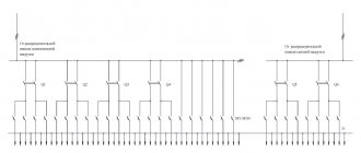
Complete transformer substations (CTS) for indoor installation consist of three-phase step-down transformers, the highest voltage of which is 6 or 10 kV, and the lowest voltage of 0.4 kV and switchgear cabinets. RU cabinets are manufactured in sectional, linear and inlet types. They consist of bus and switching parts separated by partitions. Switchgear cabinets with voltages up to 1 kV contain switching and protective equipment: retractable universal circuit breakers, ATS relay equipment, measuring instruments, as well as measuring current transformers. The control, protection and signaling circuits of PTS equipment are performed on operational alternating current. Substations have one or two transformers with a capacity of 250, 400, 630, 1000, 1600, and 2500 kVA, which are supplied filled with transformer oil with a nitrogen blanket or with an oil conservator, as well as dry with fiberglass insulation. PTS with transformers filled with transformer oil can only be used if oil collection pits are installed underneath them and the distance between two PTS is at least 10 m. Complete transformer substations are equipped with warning alarm cabinets. Depending on the order, switchgear cabinets are equipped with different designs. Installation of complete transformer substations When starting the installation of a complete indoor transformer substation, check the axes of the substation, check the base marks for the support channels of the switchgear and the transformer slides, as well as the required dimensions of the construction part. The switchgear blocks are lifted with inventory slings, which are secured with brackets. If there are no brackets, then the switchgear blocks are installed on the foundations using rollers made from sections of metal pipes. If the switchgear blocks do not have support channels, then increase the number of rollers to at least four per block. Multi-block distribution devices are installed in stages. The blocks are installed one by one, after first removing special plugs that cover the protruding ends of the tires. The installation channels of the cabinets are connected by welding using jumpers made of strip steel with a cross-section of 40 x 4 mm. After installing the blocks, the grounding bars are welded to the support channels. Distribution devices are connected to the transformer with a flexible jumper and covered with a sheet steel box, which is supplied complete with a complete transformer substation. When making connections to transformer terminals, you must be aware that excessive bending forces when tightening the nuts can cause oil leakage. The busbars are connected using bolts. The box is secured to the transformer and the input cabinet with bolts. Upon completion of the installation of the KTP units, check the serviceability of the wiring of the devices, the reliability of the fastening of bolted connections, especially contact and grounding ones, the operation of the mechanical interlock, and the condition of the insulators. After this, the high and low voltage cables are connected. To ground the PTS, the channels are welded to the ground loop in two places.
Purchasing RTP at Ezois
To buy a distribution transformer substation, you need to fill out a questionnaire, which will indicate all the necessary data for further design. Our specialists will select the optimal design of blocks and designs that will be most effective at your facility. At the same time, safety standards and ease of use are also taken into account.
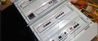
Installation of distribution substations is carried out on our territory and the substation is tested there. We work only with trusted suppliers of components; our installation specialists have extensive experience in this field, so we can guarantee a long service life of the substation and its safety. To simplify operation, each cell is equipped with a detailed electrical diagram.
Purpose of KTP
Modern PTS allow solving several problems at once:
- Reception of electricity from three-phase alternating current power lines with a nominal voltage of 6 (10) kV and an industrial current frequency of 50-60 Hz.
- Stepwise transformation of the received energy into alternating current with a voltage of 380 V (0.4 kV) and a frequency of 50-60 Hz; one phase out of three is allocated for household consumers.
- Distribution of converted electricity to end users connected via a ring (continuous distribution line in the form of a closed loop) or radial connection scheme.
The capacities of power electrical installations are designed to supply energy to medium and large consumer facilities, including:
- construction sites;
- industrial enterprises;
- residential areas, microdistricts, villages;
- communal and municipal services;
- agricultural and farming facilities.
A wide variety of designs, configurations and structures that fit most correctly into the climatic and technical operating conditions of the complete device allow you to choose an option suitable for a specific facility.
Color and letter identification
Protective conductors must be identified by a two-color yellow-green combination, according to GOST 33542-2015 [5]. The alphanumeric identification of the protective conductor shall be "PE". This identification is also used for the protective earth conductor.
The combination of yellow and green colors is only intended to identify the protective conductor.
Rice. 7. Alphanumeric designation of conductors for three-phase electrical installations in buildings
According to clause 6.3.2 of GOST 33542-2015:
“The yellow-green color combination shall be such that for any 15 mm of conductor length where a color designation is used, one of these colors covers not less than 30% and not more than 70% of the surface of the conductor, and the other color covers the remainder of this surface.
If bare protective conductors are supplied painted, they shall be painted yellow-green either along the entire length of each conductor, or in each compartment or block, or in each accessible location. If adhesive tape is used for color identification, use only two-color yellow/green tape. »
[5]
“Where a protective conductor can be easily identified by its shape, design or position, for example a concentric conductor, it is permissible not to color-code its entire length, but the ends and accessible locations should be identified by a graphic designation (see figure
or yellow-green two-color combination, or alphanumeric designation “PE.”
[5]
“If third-party conductive parts are used as a protective conductor, it is permissible not to identify them by colors. »
[5]
Rice.
8. Identification of protective conductor Important to know! According to clause 6.1 of GOST 33542-2015, identification by colors or marks is not required for:
- metal sheaths or armor of cables when they are used as a protective conductor;
- third-party conductive parts used as a protective conductor; exposed conductive parts used as a protective conductor.
PANELBOARD DEVICES WITH VOLTAGE UP TO 0.4 kV
Power distribution cabinets for connecting machines, equipment, power receivers for industry and agriculture. • PR – Distribution points are designed for distribution of electricity and protection of electrical installations during overloads and short circuits, for infrequent (up to 6 switchings per hour) operational switching of electrical circuits and starts of asynchronous motors. Cost: from 2500 rub. • YARP – YARP power boxes are used for non-private switching, both disconnecting and switching power, most often three-phase lines. Cost: from 1500 rub. • ShRS – Power distribution cabinet is designed for receiving and distributing electrical energy in industrial installations with a voltage of 380/220V three-phase alternating current with a frequency of 50Hz in networks with a solidly grounded neutral, as well as for protecting power and lighting lines during overloads and short circuits. Cost: from 4500 rub. • Y5000 – Control boxes for asynchronous motors of the Y5000 series are designed for continuous operation (starting an electric motor and turning off a rotating motor). Cost: from 2500 rub. • RUSM – RUSM series boxes are designed to control asynchronous motors with a squirrel-cage rotor in continuous operation - to start the electric motor and turn off the rotating motor. Used in environments with high humidity and dust. Cost: from 2500 rub. • Control unit B5000, BM5000, BMT5000, BM 8300, BM 8500, BM 8900, BM 9500 – designed for local, remote and automatic control of asynchronous electric motors with a squirrel-cage rotor. Cost: from 600 rub. • PKU – Push-button control stations are designed for remote control of electromagnetic devices in electrical control circuits of alternating current up to 500V with a frequency of 50 and 60Hz and direct current with voltage up to 220V in stationary installations. Cost: from 250 rub.
>Builder's Handbook | RP and TP equipment
Design and survey work
An abbreviation of three letters - PIR - denotes a set of works for carrying out engineering surveys, preparing projects, developing economic and technical justifications and working documentation, drawing up estimate documentation for construction (it may be new or involve reconstruction, as well as expansion). Depending on what conditions are specified in the contract, these works can be carried out either by the general designer or by the design customer. Have you thought about what PNR is? The definition of the abbreviation is presented in the article. Engineering surveys are carried out to obtain data on the natural conditions of the territory where construction is supposed to take place
The information obtained is an important part of the data for the project. Engineering surveys are carried out by specialized organizations that have licenses
In some cases, structural units and organizations, namely research departments, can act as performers. Have you come across the concept of “PNR”? The explanation of this abbreviation is presented below.
Depending on the complexity and size of the project being designed, geotechnical surveys are carried out by one or more organizations. In the second case, one company acts as a general contractor, while the rest perform subcontracting functions. If we consider all cases, then in most of them the entire scope of work for a particular construction is carried out by one organization
If you are interested in deciphering design and installation work, construction and commissioning, then it is important to read the information presented below
If we talk about the first abbreviation, then during the period of economic reforms most of the exploration organizations in Russia became joint-stock companies. Some were divided into small enterprises. An interesting fact is that many of them never changed their names, leaving the abbreviation TISIZ, which stands for “trust of engineering and construction surveys.”
Symbols of KTP
Explanation of symbols includes the following parameters:
- type of execution;
- connection type;
- transformer power;
- letter designation of the product;
- classification of input from the HV side;
- classification of output from the LV side;
- number of transformers used;
- HV voltage ratings;
- LV voltage ratings;
- climatic implementation according to GOST 15150 and placement category.
Manufacturers reserve the right to change (add or delete) some product data.
Main elements of electrical substations
- Power transformers, autotransformers.
- Input structures for overhead and cable power lines.
- Open (OSU) and closed (SGD) switchgears, including: Bus systems and sections;
- Power switches;
- Disconnectors;
- Measuring equipment (current and voltage measuring transformers, measuring instruments);
- HF communication equipment between substations (communication capacitors, connection filters);
- Current-limiting, regulating devices (capacitor banks, reactors, phase shifters, etc.).
- Frequency converters, current types (rectifiers).
- Transformers for own needs;
- Relay protection and emergency automation devices for power lines, transformers, buses.
- Ventilation, air conditioning, heating system.
Types of substations
Transformer substations are classified according to several parameters:
By type of electrical connection to high-voltage power lines:
Dead-end
Characterized by the ability to connect to only one highway.
Passing
The power source is two lines.
At the installation location:
In-shop (KTP-VC)
For use indoors in close proximity to the equipment being used.
Pole (KTPS)
For installation on power transmission line supports.
Kiosk (KTPK)
For outdoor use, they look like a compact metal cabinet.
Mast (KTPM)
With an open system, for fixing at a height of up to 7 meters from ground level.
Insulated with sandwich panels
A type of kiosk substations for operation at low temperatures and in conditions of increased windiness.
By type of inputs and outputs:
- cable;
- air.
By the number of current converters used:
- single-transformer;
- two-transformer.
The power of a substation is selected individually for a specific facility, based on the parameters of the total power consumption. In the segment of high-voltage power plants, there are options with power transformer power from 25 to 4000 kVA.
Our projects
all projects
- KTP capacity 52,000 rub.
- KTP capacity 52,000 rub.
- KTP capacity 52,000 rub.
- KTP capacity 52,000 rub.
- KTP capacity 52,000 rub.
- KTP capacity 52,000 rub.
- KTP capacity 77,000 rub.
- KTP capacity 82,000 rub.
- KTP capacity 87,000 rub.
- KTP capacity 92,000 rub.
- KTP capacity 107,000 rub.
- KTP capacity RUB 317,000.
- KTP capacity 327,000
- KTP capacity RUB 347,000.
- KTP capacity RUB 367,000.
- KTP capacity RUB 387,000.
- BKTP
- BKTP
- BKTP
- BKTP
- BKTP
- KTPNU
- KTPNU
- KTPNU
- KTPNU
- KTPNU
- CSR cells
- CSR cells RUB 61,000.
- CSR cells RUB 51,000.
- CSR cells 15,000 rub.
Design and survey work
L and n in electrics
An abbreviation of three letters - PIR - denotes a set of works for carrying out engineering surveys, preparing projects, developing economic and technical justifications and working documentation, drawing up estimate documentation for construction (it may be new or involve reconstruction, as well as expansion). Depending on what conditions are specified in the contract, these works can be carried out either by the general designer or by the design customer. Have you thought about what PNR is? The definition of the abbreviation is presented in the article. Engineering surveys are carried out to obtain data on the natural conditions of the territory where construction is supposed to take place
The information obtained is an important part of the data for the project. Engineering surveys are carried out by specialized organizations that have licenses
In some cases, structural units and organizations, namely research departments, can act as performers. Have you come across the concept of “PNR”? The explanation of this abbreviation is presented below.
Depending on the complexity and size of the project being designed, geotechnical surveys are carried out by one or more organizations. In the second case, one company acts as a general contractor, while the rest perform subcontracting functions. If we consider all cases, then in most of them the entire scope of work for a particular construction is carried out by one organization
If you are interested in deciphering design and installation work, construction and commissioning, then it is important to read the information presented below
If we talk about the first abbreviation, then during the period of economic reforms most of the exploration organizations in Russia became joint-stock companies. Some were divided into small enterprises. An interesting fact is that many of them never changed their names, leaving the abbreviation TISIZ, which stands for “trust of engineering and construction surveys.”