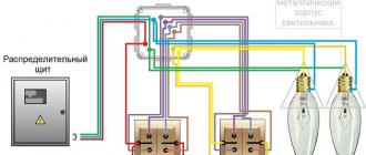
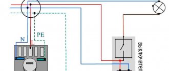
This figure shows a simplified electrical diagram for connecting a switch, sockets and lamps . It is quite common and is widely used in the electrification of residential apartments, basements, garages, industrial, construction sites, etc. Now let’s take a closer look at this scheme.
For a better understanding, the connection diagram for the switch, sockets and lamps is drawn as it is usually located during installation.
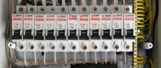
Let's start with the electrical panel. Every house and apartment must have a panel to which the input from the main power line (from the nearest power pole or from the main distribution panel on the site) is suitable. On (in) this panel, as a rule, there is an electric meter, RCD, circuit breakers, fuses and additional devices (for example, mains voltage indicators, overvoltage protection, etc.). It is from this that the entire premises (private house, apartment) is powered.
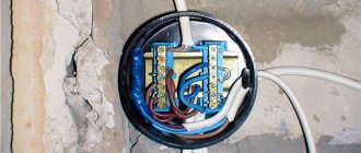
Let's assume that we have a three-room apartment. This is usually done like this: a junction box is installed in each room (it is shown in the figure as a circle). Wires (cables) from the panel are connected to it and power is taken from one of the machines on it. Such junction boxes are the switching points for all power wires (from switches, lamps, sockets, air conditioners, etc.) that are located in a given room (premises).
Now, as for the connection diagram of switches and lamps . As you understand (looking at the picture), in the connection box there is a phase (red wire) and zero (blue), which come from the panel - Color of the wires is phase, zero, ground. A phase wire is taken and a common wire (also red) is connected to it, going to the two-key switch.
In the open position of the switch, the phase simply sits on the common terminal and waits until pressing the key(s) sends it to the wire that is connected to one of the lamps. The wires going to the lamp(s) are indicated in green. When the switch is off, these wires are de-energized. By the way, they also pass through the junction box.
As you know, some types of switches have neon lighting. In the figure it is shown inside the switch as a circle with two smaller circles. This neon light bulb is connected through an additional resistance (series). This backlight should be turned on like this: one of its wires is screwed to the common terminal of this switch, and the second wire to one of the remaining terminals (on the switch).
This backlight will illuminate when the switch is in the contact breaking position. Yes, I want to remind you that this backlight works well with incandescent light bulbs. It is not advisable to connect it with energy-saving lamps (the light will simply start to dim even when it is off).
Lamps usually have several lamps. When connecting lamps separately (one part of the lamp is lit, the other, and both at once), the connection of the wires occurs as follows: one wire is taken from each of the lamps and connected into one twist or terminal block. The second wires from these lamps are grouped into two (phase) twists. As a result, the first common twist is connected to the zero coming from the junction box, and the grouped remaining two twists are connected to two wires (green) coming from the switch.
Now, regarding the socket connection diagram. Everything is very simple here. Take two wires (phase and neutral) coming from the junction box and connect them to the contacts on the socket itself.
Next, a second wire is removed from the same outlet (in parallel) and connected to another. Sockets should be connected with a parallel wire when these sockets are located close to each other (forming a group of sockets).
Read more about how to connect a block of sockets and switches here: How to install a block of electrical switches with a socket
If the sockets are located far from each other (for example, on the opposite wall of the room), then they are powered from another wire (cable) coming from a common junction box belonging to this room.
When forming connecting groups of sockets, you should remember and take into account the total load on them (total current). Since, by connecting too many sockets in one group and powering them from a common cable having a small cross-section, you can get an overcurrent on this cable and eventually heat it up (fire).
Single-key switch connection diagram
Many homeowners have to replace or install light switches. The most commonly used connection diagram is a single-key switch - one of the simplest schemes for turning on lamps or lamps. This article describes step by step how such a scheme is assembled.
Before starting any work related to electricity, the first thing you need to do is de-energize the electrical wiring - turn off the input circuit breaker, and also take measures to ensure that no one accidentally turns it on.
This is especially important if the electrical panel is located on a landing in a multi-story building or on the street.
To install and connect the switch you will need:
— the switch itself;
— PVC insulating tape.
Scheme for connecting a circuit breaker device through a socket
In order to connect a switch using a socket, a standard connection diagram is used
Important! There is always a break in the phase conductor in the breaker, and the zero goes directly to the light source:
- A distribution box is installed into which wires are fed from the existing outlet (the room must first be de-energized), wires going to the switch, and a wire from the lamp.
- We connect one core from the source of electricity consumption to zero, the phase must be connected to the switch; if it goes through the junction box, then it is connected to the core from the switch.
Switch connection diagram
In the presented diagram, the phase wire goes from the light bulb directly to the breaker; when it is in the “on” position, electricity is consumed; when in the “off” position, the load does not receive electricity.
How to choose the wire cross-section?
Often the electrical connection of a source of energy consumption, for example, a sconce from an outlet, occurs to install additional lighting, in our case it can be one or more sconces, for this reason the current is low and it is possible to select wires of the desired cross-section, but there are nuances:
- according to safety requirements and PUE, for these purposes it is impossible to use a wire with a copper conductor cross-section of less than one square millimeter;
- and a wire with an aluminum core of at least two and a half square millimeters.
When choosing a wire, you need to take into account how it is laid, so there are certain conditions for open laying:
- for a copper wire, the minimum cross-section is 1.5 square millimeters;
- The minimum value of an aluminum core is 4.0 square millimeters.
To lay a wire along the outer wall of a house or building, there are the following requirements:
- for wires with copper conductors - 2.5 square millimeters;
- for aluminum wire cores - 4.0 square millimeters.
How to independently connect a light source from a switch?
One of the simple ways, according to experts, is to connect the sconce to the circuit through a switch powered by an outlet using neutral and phase wires; this is especially beneficial when the lamp is located close to the switch.
To complete this work you need to do the following:
- Carry out installation work to install the lighting source and switch, then carry out the steps to connect them.
- From the socket from which we will connect our voltage breaker, we remove the voltage using a machine in the panel (usually the wiring is carried out according to consumption groups), and check with a “probe” for the absence of a phase.
Socket connection diagram
- Open the socket; if the work on its connection is carried out with a copper wire with a color difference, then:
- zero – blue wire;
- grounding – second wire with double color (yellow-green);
- phase is the third wire, it may be brown.
If there is no color difference and the connection is made with an aluminum wire, you need to briefly apply voltage to the socket and use a “probe” to determine the phase of the electrically conductive wire.
- We connect the wire from the switch (to its input), which is already connected to the breaker, to the socket phase, and connect the wire from the lamp to the output from the switch.
- When you don't know how to connect a double switch, the solution is the same, but from the output of the electrical circuit interrupter, each phase wire goes to its own light source, or for a chandelier to its own power consumption bulbs.
- To the neutral wire of the socket we connect the neutral wire of the switch to the light bulb; if the socket has a grounding wire, we connect it to the grounding wire from the lighting source.
- After this, the wiring is laid and all connections are insulated, as well as the assembled circuit is tested.
How to connect a socket-switch, which is assembled in a single housing?
When there is an outlet in the bedroom or in another area of the room, and you want to install a sconce or floor lamp, you can use a socket-switch device, which is assembled in a single housing, this is done as follows:
- the socket has a standard connection, phase and zero; in new buildings, euro sockets are connected with a grounding wire;
- the phase is supplied to the input of the breaker (switch), and from its output the wire goes to the lamp;
- The other two wires (the neutral wire and the ground wire) are connected directly to the lamp.
It is necessary to understand that you cannot make the reverse connection, in other words, connect the socket from the switch; it can only receive electricity from the circuit breaker in the switchboard of the house or apartment.
Connection diagram for a switch in a distribution box
Connecting a wire directly to a light fixture or switch is quite simple - it doesn't require any explanation.
This article will discuss how to connect wires from a lamp, electrical panel and switch in one junction box.
Once again we would like to remind you that all work on connecting wires in the distribution box, connecting switches and lamps should begin only after the mains voltage has been removed.
By following this simple rule, when the switch breaks exactly the phase and not the zero, you will ensure your safety and also make it safe to operate electrical equipment in your apartment.
If the switch disconnects from the load not the phase, but the neutral wire, then the wiring will always remain energized, which is not only inconvenient, but also dangerous.
For example, you need to replace a light bulb that has burned out in a chandelier. If the switch turns off the neutral wire and not the phase, if you accidentally touch the current-carrying parts of the chandelier or the base of the light bulb, you may get an electric shock, since these parts are under phase voltage.
You can determine the phase wire in the distribution wiring using an indicator screwdriver.
Again, for safety reasons, the phase wire (usually red) must be connected to the lamp socket in such a way that the light bulb is connected to the phase by the central contact of the base.
This reduces the likelihood that a person will touch the phase wire.
The switch connection diagram consists of one or more light bulbs connected in parallel, a single-key switch, a distribution box and a 220-volt power source.
Specialized stores offer a wide range of wires for electrical wiring, so for phase and zero it is better to take wires of different colors, for example, red and blue.
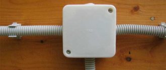
Installation of junction boxes
As already indicated, junction boxes refer to additional protection of the indoor energy system. They are installed on any branches from the main highway. When laying electrical wiring, it is necessary to ensure that connections and current-carrying conductors do not touch the ceiling, floor and walls of the room. This condition is met due to the insulation of electrical wiring and the installation of junction boxes. To connect wires, soldering using solder and flux was previously widely used, but today reliable contact is ensured by twisting the wires and using screw terminal blocks to crimp them. However, it is necessary that the connection is not accessible and there is no open contact with the enclosing structure. It is these conditions that are provided by junction boxes. There are no restrictions on the number of boxes that can be installed in a room; you just need to proceed from the economic side and common sense. There are only some restrictions on the installation location. For example, in bathrooms, it is prohibited to install junction boxes closer than sixty centimeters from the bathtub or shower tray and below three meters from the floor level. As a rule, for safety reasons, junction boxes are installed outside these premises. Today, the following types of junction boxes are widely used:
- Junction boxes for internal installation - used when installing hidden electrical wiring;
- Open installation junction boxes - used when installing external or open wiring. Sometimes they are also called “overlay boxes”.
The main requirement for the installation of junction boxes is subsequent convenient maintenance and access. It is necessary to avoid situations where, in order to carry out work in the junction box, it is necessary to dismantle or destroy finishing or decorative elements.
Connection diagram for socket and switch in one junction box
Very often, a distribution box is installed in each room of the apartment, where all the switches, lamps and sockets of this room are connected.
In this case, due to the large number of wires going to the junction box, it is quite difficult to figure out what needs to be connected where.
How to connect a socket and switch to a distribution box?
Let's consider the option when a socket and a lamp are simultaneously connected to one distribution box.
So, two wires come from the distribution board to the box - red (phase) and zero (blue).
The procedure for connecting the switch and lamp is exactly the same as discussed above.
The socket is connected parallel to the supply wires: the socket phase is connected to the supply phase (both wires are red), and the zero from the socket is connected to the neutral supply wire (both wires are blue).
The connected wires must be well crimped and soldered, after which they are securely insulated and neatly placed in the box.
Features of electrical wiring installation
All electrical installation work is carried out only after installing the electrical panel and meter. After which the locations of the switching equipment are determined. In order to correctly lay wires and install socket boxes, an inspection of the cable route, conditions for laying wiring and electrical products is carried out.
The precision of electrification guarantees not only an aesthetic appearance, but also the safety of the entire home. So, when installing a socket box as a distribution box, you must follow the installation rules, these are:
- Fix the socket box in a wall made of brick, concrete, plasterboard using a building mixture.
- Install the socket box flush with the wall surface with the wiring closed.
- To fasten the glass, use special clamping screws with plates.
When laying the cable, you should use special fasteners that will protect it from mechanical damage and act as grounding. When designing an electrical network through sockets and switches, it is necessary to use only high-quality equipment.
Recently, installation socket boxes with a more in-depth shape have become in great demand, so that the stock of wires formed by loops or folds can fit compactly without sharp creases.
Switch and socket connection diagram, detailed manual
Electrical wiring of any room begins with a socket, switch and light bulb, be it an apartment, a country house
house, garage or basement. The ability to perform a circuit diagram for connecting a switch and socket will be relevant always and everywhere, when
any repair, redevelopment and construction. In this article you will find a detailed guide that discusses this issue in detail. By following the step-by-step instructions below, you can easily complete the switch and socket connection diagram , learn it yourself and be able to teach it to others. So, let's move from words to action. Let's look at the question from the very beginning to the end. The installation of any electrical circuit always begins with the junction box. Next, wires, socket boxes, electrical circuit protection devices, sockets, switches and lamps are installed. Let's go in order.
Electrical Wiring Safety
Upon completion of the installation of electrical wiring, it is necessary to carry out a set of measurements to ensure that the system is ready to use modern household equipment and appliances. Checking the functionality of the electrical panel, wires, cables, sockets, switches makes it possible to correct mistakes in a timely manner. Testing shows that:
- electrical wiring contacts have reliable grounding;
- connections are correctly connected;
- there is no extraneous voltage or damage to the insulation;
- automatic protection device matches the wiring.
Accurate measurements of electrical wiring can only be carried out with the help of electrical laboratory specialists. For testing, control and measuring equipment is used, which shows losses and electricity consumption. Sockets, switches, and lamps especially require preventive inspection to avoid short circuits.
We mount installation elements
For maximum clarity and clarity, we will analyze the full circuit installation cycle from start to finish. Thanks to this, we will give the most detailed answer to the question of how to connect an outlet with a switch. As an example, let’s take a diagram of hidden electrical wiring, something that is usually located under a layer of plaster.
We install the distribution box.
Next we need two sockets. Detailed instructions for installing a socket box (mounting cup) are described here.
We will install a switch in one, and a socket in the other.
Now let's mount the DIN rail, in our case it will act as part of the power cabinet; a circuit breaker will be installed on it, which will protect the electrical circuit from short circuits and overloads, which have such a detrimental effect on all elements of the circuit.
The preparatory work can be considered completed.
The last detail that completes the first stage of installation is the lighting element. In our example, it will be a light bulb with a socket, clearly, simply and clearly. Therefore, we will move its installation to stage number two.
We change the purpose of the electrical point or connect one from the other
No matter how much you want to do everything as quietly as possible, you still have to run wires. Of course, this is not a stretch across the entire room from the junction box, but still. There are only two options for laying the wire - open and hidden. In the first case, you can use a PVC cable duct, but in the second, you will have to groove the wall to hide the wire.
Replacing a socket with a switch and vice versa
Prices for adjustable switches
Dimmer
We’ll start with what we think is the simplest thing – changing the purpose of the electrical point. This measure can be useful when an old switch is installed that is no longer used, or there are enough sockets in the room, but there is very little light.
The principle of connecting a switch and socket
In the description of the work, we will, first of all, focus our attention on the changes that need to be made. We will describe dismantling and installation only once, so as not to repeat it all the time. We hope that you can cope with this without prompting, otherwise we do not advise you to get into the electrical network.
Attention! All work with electrical wiring is carried out only if the power supply is first turned off. Otherwise, you risk receiving a serious electric shock, which can even lead to death. All work must be carried out by trained specialists, so be aware of what you are dealing with.
We replace the socket with a switch.
Table 1. Step-by-step instructions for installing the switch.
| Step, photo: | Description: |
| Step 1. Removing the socket.
| The work begins by removing the old socket. To do this, you first need to unscrew the screw in its center - it holds the front plastic panel. Next, you will see two more screws at the edges, which are responsible for wedging the clamps in the box. There is no need to unscrew them all the way, just loosen them and pull the base of the socket out of the box, as shown in the photo. |
| Step 2 : Disconnecting the wires. Disconnecting the wires | All wires are clamped in the socket with special terminals, which are tightened with screws. That's right - we unscrew them too. We move the socket to the side, and then temporarily insulate the exposed ends of the wires. Advice! At this stage, you should determine where the phase is and where the zero is. For this we use a screwdriver with an indicator. Detailed instructions will be in the video at the end of the article. |
| Step 3. Removing the junction box cover.
| Here is a vivid example of a situation where you will need access to the distribution box, because in order for the switch to work as a socket, you need to reconnect the wire terminals. |
| Step 4: Labeling the wires. Continuity of wires | So, we opened the box, but what to do next, because there is simply a huge amount of wires inside? How to find the ones you need? Yes, not everything is as simple as it seems at first glance. In order not to confuse anything or cause a short circuit, we will need to ring the wires. A special tester is used for these purposes, like the one used by the master in the photo. ·First of all, we need to find the phase and neutral of the common supply wire. How lucky you will be if all connections are made using terminal blocks! Otherwise, you will have to unwind the electrical tape and disconnect all the twists, which takes a long time, and there is a risk of breaking the wire. · We can roughly understand which wire we have as a group wire, and which one goes towards our former outlet, in the directions in which they go into the wall. · We disconnect all the wires and move them apart so that they do not touch each other in any way. At the same time, we look to see if they match in color. We recommend additionally gluing markers on which the group is marked, so that later there will be less hassle with dialing. · Next, apply voltage to the power cable and touch each terminal one by one with an indicator screwdriver - the light on the screwdriver should light up. · Then we take the tester, touch the found phase with one end, and go through the wires with the other until the lights on it also light up. This is how you find zero. Turn off the voltage, mark the wires and move on. |
| Step 5: Find the wires going to the outlet. We are looking for wires going to the outlet | We return to the outlet and connect the two wires that were previously phase and zero. Again we go to the box and use a tester to look for their return terminals, guided by the color of the insulation. You understood correctly, the circuit turned out to be closed and when you touch the necessary terminals, the light on the device will light up. |
| Step 6. Connecting the wires in a new sequence. Connect the wires in a new sequence | Next, we twist the wires again according to the marks, as they were connected earlier, except for the terminals from the socket that we found. One of these wires is connected to the phase, and the second will go to the lamp, from which one or two more wires (neutral and ground) will return to the socket. |
We connect the switch to the wires in the box, secure it and use it. Replacing a switch with a socket is carried out in reverse order, following the same steps, so we will not describe the process again.
We connect the switch from the outlet
Let's move on. On the way we have a serial connection of one device from another. Let’s say right away that the PUE standards do not provide for such alterations, but sometimes the situation dictates its conditions, and not vice versa. Therefore, we will act in the following order:
Removing the socket
- Unscrew the socket and remove it from the box. There is no need to disconnect the wires.
- Further actions will depend on the location of the lamp. If it is located in close proximity to the switch and is not yet connected to the network, we will need to connect a wire with the required number of cores to it using any of the methods listed above.
Wires can be neatly hidden in the cable channel
- This method of connecting a switch from an outlet is the safest and most correct.
- So, we connected, for example, a lamp and a switch with a two-wire wire. In this case, the zero wire remains intact, while the phase is cut, and the resulting ends are connected to the switch. We pull the wire further and insert the sockets into the box. Then the phase is connected to the phase , and the zero to the zero .
Three wires are connected to a grounded outlet
- If the wires from the lamp go into the junction box, then to connect the switch the socket must be grounded; three wires must be connected to it.
- We throw a two-wire cable from the switch into the socket box, having previously connected it to the device. We connect one terminal to the phase, and the second one to the ground wire, which must first be pulled out of the socket. The contact must be reliably insulated with PVC electrical tape . As you understand, in this way we consciously refuse to ground the outlet. This is only permissible if it powers a device whose body is made not of metal, but of plastic. That is, he will not be electrocuted.
Wires in grooves are a more reliable solution
Prices for popular models of wall chasers
Wall chaser
- Next, in the junction box we find the terminal of the same ground wire to which we connected. You already know how to do this. We connect this wire to the phase wire, which goes to the lamp.
As a result, we have a regular circuit, only the power to the switch will come not from the group wire, but from the socket.
Connecting an outlet switched via a switch
Connecting the socket from the switch
Prices for sockets with grounding
Grounded socket
And for last we left you with something “delicious”. This scheme of all those listed is the most difficult to implement, and for its implementation there is one prerequisite - the switch must be a two-key switch. That is, there are three wires going to it from the box, one of which we will also use for our needs, and the switch will become a single-key switch. Not the most elegant solution, but in some situations it can be useful as a temporary measure, e.g.
Electrical outlet layout option
So, we proceed in the following sequence:
- We remove the switch from the box and see three wires going to it. One of them will be the phase from the group wire - we will calculate it using the same indicator screwdriver.
Checking with an indicator screwdriver
- We connect to the terminal into which it enters with the end of the wire. This will be the phase for the socket. Is it worth reminding that the socket must be installed and a wire must already be connected from it to the switch box.
- Next, unscrew any of the remaining wires and connect it to the second wire from the outlet, insulating the connection.
It is not worth soldering the wires in the junction box, as it will be difficult to disconnect them later
- We go to the junction box and find this previously disconnected wire. It will need to be connected to neutral, but before you unwind it, mark the wire to which it is connected. He will go to the lamp. We don't want them to stop burning, do we? No! So, let's connect it to the third wire, which we left untouched in the switch, also in the junction box. As a result, both lamps will be turned on from one key.
Find out how to connect wires in a junction box, and also familiarize yourself with popular methods in a special article on our portal.
Laying the wires
First of all, let's connect the wire feeding the junction box. In our example, we use a wire of the VVGngP brand; a three-core wire with a cross-section of 2.5 squares is used as the power supply. The cross section was selected using the calculation method based on the load on the chain; you can easily perform these calculations on your own. Here you will find a detailed description of how to independently calculate the cross-section of a wire, I assure you there is nothing complicated here.
On both sides it is necessary to leave a reserve of wire for connecting electrical wiring elements (breaker, socket, switch) of 10-12 centimeters, in the junction box 10-15 centimeters. Wires that are too short will be inconvenient to connect and connect, so it’s better not to save much.
Next, let's connect the wire to the socket.
Here you will need a wire with a core cross-section of 2.5 square.
1.5 square meters per switch.
Now, let’s lay the wire for the lighting; for us it’s a light bulb with a socket.
We have laid all the wires necessary to complete the circuit, let's move on to the third stage.
Recommended wires for boxless wiring
Conductors with 4-6 mm2 conductors were laid between the distribution boxes, and taps were made from it for individual sockets and lighting fixtures with thinner wires. The common wire was designed for the load of all consumers in the group. In our version, a cross-section of 4-6mm2 will not be very convenient for connecting to contacts and packaging in socket boxes.
Such wires are rigid, difficult to clamp with bolted connections of the contacts, sometimes the terminals even break. It is very convenient to use 2.5 mm2 copper wire, it is elastic and fits perfectly into the terminal grooves. The current loads that the cores can withstand can be seen in the table. Based on this, make calculations on the number of sockets in the group and the power of connected household appliances.
| cross-sections of copper conductor for various current loads | ||||||||||||||
| Current in A | 1 | 2 | 3 | 4 | 5 | 6 | 10 | 16 | 20 | 25 | 32 | 40 | 50 | 63 |
| S - in mm2 | 0,17 | 0,33 | 0,52 | 0,67 | 0,84 | 1 | 1,7 | 2,7 | 3,3 | 4,2 | 5,3 | 6,7 | 8,4 | 10,5 |
| Ø in mm | 0,45 | 0,65 | 0,81 | 0,92 | 1,02 | 1,13 | 1,45 | 1,87 | 2,05 | 2,32 | 2,60 | 2,92 | 3,27 | 3,66 |
Based on the calculated values, a 2.5 mm2 wire can withstand a load of up to 16A. Data have been collected on the approximate powers and currents consumed by household appliances for various purposes. Using this information, you can guess how many and what devices to include in the outlet group.
| Type of household appliances | power in W | current in Amperes |
| Old style incandescent lamps | 60 – 250 | 0,3 – 1 |
| Small-sized heating appliances: teapots, coffee pots and boilers | 1000 – 2000 | 5,5 – 10 |
| Stationary and portable electric stoves | 1000 – 6000 | 6 – 55 |
| Microwaves of various brands | 1500 – 2200 | 8 – 10,5 |
| Kitchen electric meat grinders for non-industrial purposes, for home use. | 1500 – 2200 | 8 – 10,5 |
| Toasters for baking bread | 500 – 1500 | 2,5 – 8 |
| Equipment for preparing grilled dishes | 1200 – 2000 | 7,5 – 8 |
| Blenders and mixers | 500 – 1500 | 2,5 – 9 |
| Food processors | 500 – 1500 | 2,5 – 9 |
| Electric oven | 1000 – 2000 | 5,5 – 8 |
| dishwashing machines | 1000 – 2000 | 5,5 – 8 |
| Household washing machines | 1200 – 2000 | 5.5 – 8 |
| Electric shoe or clothes dryers | 2000 – 3000 | 8 – 12 |
| Irons for non-industrial use | 1200 – 2000 | 5.5 – 8 |
| Floor and portable vacuum cleaners | 800 – 2000 | 3.5 – 8 |
| Spiral heaters | 500 – 3000 | 1.8 – 12 |
| Hand-held hair dryers | 500 – 1500 | 1.5 – 7 |
| Split systems and air conditioners | 1000 – 3000 | 6 – 12 |
| computers | 300 – 800 | 0.8 – 3,2 |
| Hand-held power tools (grinder, drill, hammer drills, jigsaw, etc.) | 500 – 2500 | 1.8 – 12 |
For lighting devices, it is recommended to lay a three-wire cable from 0.7 to 1 mm2. Practice shows that this is quite enough, especially when LED lamps and energy-saving lamps are used.
Installation and connection of electrical wiring elements
Let's start by installing the security device. For our circuit we use a two-pole circuit breaker rated at 25 Amps. The selection of the required amperage of the protection device is made after calculating the cross-section. We immediately decide on the color of the wire:
- blue, white with blue stripe - zero (neutral)
- yellow with green stripe - ground (grounding)
- the remaining wire will be the phase usually it can be black, white, brown, red, orange or white with a black or brown stripe
In our example, there are two types of phase wire colors: white and white with a brown stripe.
In order not to get confused in the colors of the wires, it is best to use wire from one manufacturer.
A power outage will be required before further work can be carried out. Turn it off. We check the absence using a voltage indicator. How to do this is discussed in detail in the article voltage indicators. We remove the outer layer of insulation of the wire, measure out the required amount for connection, remove the required amount of the second insulating layer from the copper core and connect the wires to the circuit breaker. For more details about the connection, read the article, instructions for connecting a two-pole circuit breaker.
We connect the yellow-green core to the ground wire through a contact clamp. This connection makes sense if you have a grounding loop in your apartment or house and your supply wire, namely its grounding conductor, is connected to it. You can find out more about whether your apartment has grounding by reading the article, grounding in an apartment.
Now we connect the outlet. We strip the wires, measure the required amount, insert the wires into the contact clamps, tighten the screws, and check the reliability of the fixation. For more details, see the article about connection; you can read the article on how to connect an outlet.
We install the socket mechanism in the socket box.
Next, we connect a single-key switch. We prepare the wires, remove the outer insulating layer, measure out the required amount and connect the stripped wires to the contact clamps. We isolate the unused ground wire.
Wiring connection methods
Bonding of electrical conductors in accordance with technical requirements and current instructions is carried out using soldering, crimping, crimping using appropriate tools. When choosing a contact connection method, it is necessary to consider what the fastening is for and where it will be placed.
At the points of connection and branching of wires, a reserve is always left for reconnection in the event of a malfunction. Today, the most versatile, efficient electrical connections are screwless terminals. Simple and convenient, suitable for all types of conductors of different cross-sectional diameters.
The clamp consists of a high-quality steel spring that is resistant to aggressive environments and a current bar made of electrolytic copper of special tinning, and is fixed on the contact area with a screwdriver. The terminal has no restrictions on currents and voltages; it even connects conductors to the sleeve. Meeting modern requirements, the clamp has a reduced size, due to which it does not take up much space in the electrical box.
Connection diagram of a switch and socket, connection of wire cores in a junction box
It remains to complete the last final and most critical stage of the scheme. Let's get started.
To make the connection of wires simple and clear, let's start with a switch and a lamp (in our case, a socket and a light bulb). We prepare the wires and remove the outer layer of insulation.
In our example, a three-core wire is used; the choice is determined by its functionality, since if necessary, the circuit can be remade without any problems. For example, a single-key switch can be converted into a two-key switch, or, on the ceiling there was a simple lamp with one light bulb, but it became a chandelier (some chandeliers use a system of partial switching on of lamps, for example there are 10 of them, one key will switch on 6, the second 4, and both, respectively, all). You can also use the third wire as grounding for the body of a lamp or chandelier, for example in rooms with high humidity. Therefore, we isolate the extra yellow-green core, which we will not use now, and put it in the distribution box so that it does not interfere.
Now we strip 3.5-4 centimeters of copper cores of all remaining wires.
Next, we connect two wires to each other, the blue wire from the wire coming from the switch (outgoing phase) and the white phase wire from the wire going to the light bulb. The connection is made by twisting the wires together.
Now, remove the insulation from all other wires.
For subsequent connection, we strip the insulation of all 6 cores, 3.5-4 centimeters each.
Next, we connect the wires to each other according to color, three blue (in our example, these are white wires with a blue stripe).
Two yellow with a green stripe.
And three phase ones, one white and two white with a brown stripe.
The scheme is almost complete. Now you need to check that it is being done correctly. Screw the light bulb into the socket.
We separate the strands in the distribution box so that they do not touch each other and apply voltage to the circuit breaker for our circuit. Turn on the machine, move the lever to the up position.
We press the switch key, the light comes on.
The socket can be checked using any electrical appliance; we insert its plug into the socket and check its functionality.
Everything is fine, everything works.
Now turn off the electricity and use insulating tape to insulate the twists.
Carefully place them in the distribution box.
Main conclusions
You can connect a socket to a switch for various purposes and in different ways:
- Independently in one housing for convenient use, when the power supply for electrical appliances and the switching mechanism for the chandelier are in one place.
- In a switchable module for connecting a carrier with a light bulb, heater or tool.
- The switch is powered from the contacts of the socket when the lamp is located nearby, and it is unprofitable to wire it separately.
- The socket is connected from a switch temporarily instead of a one-button mechanism, or permanently from a two-button mechanism with the obligatory transfer of contacts in the distribution box.
The main thing is not only to connect all the contacts correctly, but to ensure their safe operation in the future. Therefore, when choosing a circuit and conductors for connecting a socket, switch and light bulbs, you need to correctly select the wire according to its cross-sectional area. Also, we must not forget about the personal safety of the master and always check the presence of voltage in the network before work using a measuring tool.
Electrical wiring of any room, be it a huge country house or a small outbuilding (basement, garage, country house), includes three main elements - a switch, a socket and a light bulb. While they remain relevant always and everywhere. During repairs, construction or redevelopment, you will definitely encounter them. Therefore, basic knowledge of electrical engineering will not be superfluous - what is the connection diagram for a switch and socket, how does it work and what materials and tools will be required for its installation?
Below are detailed step-by-step instructions, with the guidance of which even a not very experienced electrician will be able to install sockets and switches with his own hands.
Switch and socket connection diagram
By installing the circuit ourselves, we saved:
- time to search and money to call an electrician - 200 rubles
- installation and connection of a two-pole circuit breaker - 300 rubles
- installation of a grounding contact - 150 rubles
- installation, grouting of the internal junction box - 550 rubles
- assembly of the distribution box, twisting method - 300 rubles
- installation of a lamp, chandelier with connection (450 rubles for 1 lamp, chandelier from 800 rubles) - average price 600 rubles
- installation of a socket box (brick wall 200 rubles - 1 piece), we have 2 pieces - 400 rubles
- installation of a hidden socket (1 piece for 200 rubles), we have 2 pieces - 400 rubles
- installation of a single-key switch - 150 rubles
- installation of wires open on the wall up to 2 meters (35 rubles - 1 meter), for example 4 meters - 140 rubles
- installation of wire open wall, ceiling, over 2 meters (50 rubles -1 meter), for example 15 meters - 750 rubles
- wall gating 19 meters (120 rubles - 1 meter) - 2280 rubles
Our total savings amounted to: 6220 rubles
The cost of electrical installation services is described in detail here.
We also received a detailed answer to the question of how to connect an outlet with a switch and learned how to independently complete the circuit and now we can safely use the knowledge gained.
Location type
A switch with a socket in the same housing may have different locations. There are vertical and horizontal devices. The block can also be external or internal.
In the first case, the electrical network element is installed for open wiring. In this case, no recess is made in the wall for the socket box. Using a strip, the system is installed on the wall surface. The wires are covered with special boxes. When installing hidden wiring, it is better to purchase a socket with an internal switch. The device is mounted in an oval socket box. It is installed in the thickness of the wall. In this case, the wires approach the block through the shafts.
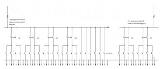
General scheme of premises electrification
The general scheme of electrification of a room can be divided into two parts - powering consumers and providing lighting.
In the first case, everything is simple - wiring is thrown from the distribution board (if necessary, it is divided), thanks to which branches are created, and brought to the sockets, through which consumers are connected to the electrical network.
The sockets themselves are constantly energized after connection.
In the case of organizing room lighting, not everything is so simple, since it is necessary to create a branch that provides for the possibility of de-energizing lighting elements - light bulbs.
For this purpose, the circuit contains switches (switches), the task of which is, if necessary, to interrupt and restore the voltage supply circuit to the consumer.
For the normal functioning of indoor lighting and to ensure safety, there are certain schemes for connecting lighting devices through switches to the electrical network.
Moreover, there are several varieties, which allows you to organize the connection of light bulbs according to the provided layout.
For example, with just one switch you can control the lighting of several rooms, independently of each other.
Previously, they used switches that cut into the wiring. That is, the wiring was thrown directly from the distribution board to the light bulb socket, and then the phase core of the wire was cut in the right place, and a breaker was installed in this gap.
This method of powering lighting elements is now practically not used and the types of lamp power connections are somewhat different, but the principle is the same.
Features of twisting single-wire wires
Single-core wiring is more difficult to twist than multi-core wiring. There are a number of reasons for this:
The current-carrying core is made of a rigid metal rod. If the cross-section is large enough, then it will not be possible to bend it with your hands. The wire has low ductility
It is susceptible to kinks, so you need to work with it with extreme caution. When stripping insulation, the knife blade must be held at an angle of less than 30° to the axis of the wire. Otherwise, the tip will cut into the current-carrying core and damage it. Strippings are carried out no shorter than 50 mm
This is the only way to ensure a good connection. It is advisable to check the finished twist under load. During operation, it should not heat up more than a solid wire without a connection.
Tags: machine, beat, sconce, view, harm, choice, switch, house, , clamp, grounding, replacement, isolate, insulation, cable, how, design, circuit, , installation, voltage, neutral, crimping, soldering iron, connection , potential, rule, check, wire, project, laying, start, , work, size, repair, socket, row, garden, light, lamp, network, twist, connection, connection wire, ten, type, current, , shield, electrical panel, effect
General provisions
Next, we will consider the most common schemes for powering the lighting elements of a room.
The features of creating such branches largely depend on the number of lamps connected to them, as well as their control using a switch.
But in any case, the created branch includes:
- Switch (one-, two-, three-key);
- Lamps with sockets;
- Junction box;
- Wires (two- and three-core).
A little about the features of the breaker.
Any switch has two outputs - input and output (there may be several of the latter).
Moreover, both of them belong to the same line, that is, if a phase is connected to the input terminal, then it will also be at the output.
By moving the key to a certain position, the contacts of these terminals are connected or disconnected, thereby closing or opening the circuit.
Before describing connection methods, let us immediately remind you of safety precautions when carrying out work.
To avoid electric shock, turn off the power supply and take steps to prevent accidental restoration of power before work is completed.
Types of junction boxes
At the moment, the market offers a wide variety of junction boxes of a wide variety of designs and shapes.
Our article discusses only the box for connecting hidden wiring. Therefore, we will dwell in detail on products of this type.
So:
- First of all, all distribution boxes can be divided according to their shape. For hidden wiring, round ones are most often used. Their diameter and depth can vary greatly. So the diameter usually ranges from 60 to 100 mm, but the depth is usually from 30 to 50 mm. But if you have the right desire, you can find junction boxes for hidden wiring in other sizes.
- Square boxes are also widely used. Usually their sizes are comparable to those of round products. That is, starting from 60×60 mm and ending with products larger than 110 mm. The depth of square boxes usually does not exceed 30 - 50 mm.
- Rectangular junction boxes are also widely used. Here the range of sizes is even greater, but the total area is comparable to boxes of other shapes. Rectangular and square boxes for hidden wiring are used a little less frequently, although here it all depends on your wishes and technical conditions.
- In addition, junction boxes for hidden wiring differ in the material they are made of. According to clause 2.1.27 of the Electrical Installation Rules, they must be made of fireproof and non-combustible materials. When laying wires over combustible materials, metal junction boxes should be used. If the wire is laid using fireproof materials, then using fire-resistant plastic boxes is sufficient.
- If previously all distribution boxes were made hollow, now models with terminal blocks inside have appeared on the market. This allows for better connection of wires, and also helps to organize them inside the box. And although the price of such products is somewhat higher, their convenience is undeniable.
- Well, the last and very conditional division of distribution boxes is the presence of fastenings. It allows you to fix the products in the wall more efficiently and reliably, but if they are mounted on cement mortar, this advantage is very doubtful.
One lamp - one switch
The simplest circuit consists of one lighting element and a single-key switch.
Theoretically, the connection does not differ from that described above - the neutral conductor goes directly from the distribution board to the consumer, but a breaker is inserted into the phase conductor. But almost everything looks a little more complicated.
To make this type of connection, you first need to decide on the location of the junction box.
It should be installed as close as possible to the installation location of the switch, while making it easy to access.
The number of wires required to create a branch directly depends on this. Its optimal location is under the ceiling above the switch.
And then everything is simple:
- We determine the location of the lighting element - the lamp (for example, in the center of the ceiling);
- We select the installation location of the breaker (conditionally - below the distribution box);
- We insert the wiring coming from the distribution board into the distribution box;
- We lay the wiring along the ceiling (along the shortest possible path) from the lamp socket and also put it into the box;
- All that remains is to lay the wire from the switch to the junction box.
For simplicity, we will designate the wire going from the switchboard to the box as “input”, and from the box to the consumer as “output”.
For a circuit with a single-key switch and one lamp, two-core wires are used.
After laying all the wiring (in an open or closed way), all that remains is to connect everything correctly and for this it is important to determine which core is phase and which is neutral.
You can find out this using an indicator screwdriver, making an appropriate check at the terminals from the distribution board before turning off the power supply.
To make it clearer, let's look at how to connect everything correctly using different colors of the braiding of the wiring cores.
For example, to create a power branch for a lighting element, a wire with cores painted brown and blue was used.
When connecting the input wire to the distribution board, the brown wire was connected to the phase terminal, and the blue wire to the neutral terminal.
Knowing this, all that remains is to connect everything correctly in the junction box.
Since the “zero” goes directly to the consumer, we connect the blue (zero) input core to the corresponding output wire.
It remains to include a switch in the circuit. A two-core wire will also be thrown from it to the distribution box, but in this case it is two parts of one line (phase).
We take the brown (phase) input wire and connect it to any of the wires, for example, also with the brown one leading to the switch.
All that remains is to connect the blue wire coming from the switch to the brown wire of the output.
Next, all connection points must be properly insulated, and only after this, the functionality of the created branch must be checked by applying voltage to it.
We examined in detail the method of connecting one lamp to a single-key breaker.
All subsequent schemes are built according to the described principle, so we will indicate only their key points.
What is needed to switch the circuit?
Electrical wiring can be open or hidden. In this article we will consider the connection of sockets and switches made according to the second option, when all electrical switching is hidden under a layer of plaster. Hidden design is the most common type of electrical wiring; open wiring is usually used as a temporary option.
Preparing the walls
Before connecting a socket and switch in the room, you need to prepare holes in the wall for their installation and grooves in which the wires will be laid. There should be three holes in total - for the junction box and for the connected switching devices.
It’s better to draw an approximate drawing on a piece of paper in advance, where exactly you plan to connect the switch and socket, and what route the wires will take to these places.
The hole for the distribution box is made, as a rule, under the ceiling, 10-15 cm lower. Holes for switching devices are made at the site of their planned installation. It is better to install the socket at a distance of 30 cm from the clean floor, where household appliances will be connected to it. It is advisable to install the switch at the entrance to the room at the level of an adult’s lowered hand - about 90 cm from the clean floor. These works are performed with an electric drill with a special bit for brick or concrete, a hammer drill with a Pobedit drill, an impact drill or an angle grinder.
When installing gates, consider several important rules:
- They can only be horizontal or vertical; no tilting is allowed.
- The entire path of the groove from the distribution box to the installation sites of the socket and switch must pass with a minimum number of turns.
- Vertical grooves cannot be brought closer to window and door openings less than 10 cm, and to gas pipes - less than 40 cm.
To install the grooves, you can use a hammer and chisel, a hammer drill, a grinder or a special tool - a wall cutter.
When all the holes and grooves are ready, thoroughly clean them of dust using a vacuum cleaner.
Installation elements and tools
To perform the electrical part of the work you will need the following materials and tools:
- distribution (socket) box, in which all wires are connected;
- two plastic or polypropylene mounting boxes (socket boxes), they are needed in order to securely fasten the switching devices in the wall openings;
- indoor socket;
- indoor switch with one key;
- lighting fixture;
- set of screwdrivers (flat and Phillips);
- knife or stripper for removing insulation from conductors;
- pliers with insulated handles;
- clamps or insulating tape;
- indicator screwdriver.
To switch the entire electrical circuit, you will also need a two-core wire. Nowadays, electrical goods stores offer a huge assortment of wires and cables, so immediately buy one so that each core has its own colored insulation, for example, red and blue. This will make it easier to switch the circuit; you won’t have to look for phase and zero with instruments, you’ll just need to connect wires of the same color.
In order to fix the wires laid in the grooves, you will also need alabaster and a spatula.
Connecting a two-gang switch
The next one will be a circuit that uses a two-key switch.
A feature of its design is the presence of two output pins, each of which can be connected to the input (phase) pin independently of each other.
This allows you to create two separate branches from one input wire, for which power control is provided with its own switch key.
Typically, a two-key switch is used to power two lamps, but there are situations when only one lighting element needs to be powered, that is, to create one branch.
In this case, the connection does not differ from that described above. The only thing is to decide which key will be working and connect a phase conductor to its output terminal.
With this connection, the second key will be disabled.
Now let's look at the features of connecting two light bulbs to such a breaker. That is, in essence, we create two branches from one phase core.
The difference from the circuit described above comes down to the fact that we will have two outputs from the box (each to its own lamp).
That is, the distribution box should include 4 wires - an input wire, two output wires and one from the switch.
Another important point is that you will have to lay a three-core wire from the breaker to the distribution box.
One of the wires will be connected to the input terminal of the switch, and the other two to the output terminal.
Next, all that remains is to connect everything correctly. Here, for convenience, you should also use the colors of the braids.
For example, the third color in a three-wire cable will be green.
The connection is made like this:
- We connect the neutral wire (blue) from the input to two output wires of the corresponding color (you should get a twist consisting of three wires);
- We connect the input phase wire (brown) with the same color leading to the switch;
- The remaining two wires of the cable leading to the switch must be connected to the phase wires of the terminals. That is, the blue one needs to be connected to the brown one of one branch, and the green one to the brown one of the other branch.
All this is more clearly presented in the diagram.
After connection, all twists should be insulated and only then checked for functionality.
Important to know: Wireless switches greatly simplify the connection of lampshades with one bulb or large chandeliers.
Bolted connections
Bolted connection
This connection is quite reliable, but cumbersome. It is not suitable for modern distribution boxes due to its dimensions, but for large old-style boxes it is just right. This method can be used to connect both homogeneous and dissimilar metals. The work is carried out as follows:
- A steel washer is placed on the bolt.
- The insulation is removed from the conductors and they are formed into a ring.
- The first ring is put on the bolt.
- Then comes another steel washer, which is placed on the bolt after the first.
- The second connecting wire is put on top.
- This entire “sandwich” is clamped with a nut.
- In the end, everything needs to be insulated.
It is this design that makes the contact bulky. If you need to connect several pairs of wires, then this option will not be the best.
How to connect a lamp through a switch from an outlet
They use conductors with three or four cores that perform different functions, and when separated, they are stripped of several centimeters of insulation. Of course, the apartment must first be de-energized. Wires and individual cores are connected according to a pre-designed circuit, making sure that they are drawn in smooth, straight lines and do not form knots or interweaves. If the installation is carried out in a room whose walls are made of wood, it is necessary to lay out the paths in advance using plastic insulating plates. To lay electrical wiring routes hidden, you need grooves. Special channels are allocated for this option in reinforced concrete buildings.
When planning to replace a socket with a light control device or link them together, it is advisable to first evaluate the limitations imposed by the procedure appropriate to a specific task. Having decided to carry out installation work, you can purchase the necessary device with parameters suitable for the selected electrical circuit.
Advantages of three-key devices
The comfort of modern life largely depends on the presence in the house of a large number of lighting sources, often even several times greater than human needs.
The three-key switch is a truly necessary device in modern houses and apartments
Triple switches are mainly used in houses of non-standard configuration in the following cases:
- when it is necessary to organize the lighting control of several rooms from one node;
- if there is a multi-level lighting system in the room.
Three-key devices have some advantages over all the usual switches due to their design features:
- simplification of wiring in walls and other structures;
- improving the appearance of the room;
- reducing the consumption of finishing materials.
Due to frequent use, such devices do not have a very long service life, about 8-10 years. Failure of switches most often occurs due to two faults:
- mechanical (breakage of the housing and fasteners);
- electrical (destruction of contacts).
Tools
Before proceeding to connecting the switch to the network, you need to prepare a number of tools:
- curved, straight and indicator screwdrivers;
- connector;
- sharpened knife;
- pliers.