Because you need to competently solve two problems at once:
- Limit the forward current through the LED to prevent it from burning out.
- Protect the LED from breakdown by reverse current.
If you ignore any of these points, the LED will instantly be covered with a copper basin.
In the simplest case, you can limit the current through the LED with a resistor and/or capacitor. And you can prevent breakdown from reverse voltage using a conventional diode or another LED.
Therefore, the simplest circuit for connecting an LED to 220V consists of only a few elements:
The protective diode can be almost anything, because its reverse voltage will never exceed the forward voltage across the LED, and the current is limited by a resistor.
The resistance and power of the limiting (ballast) resistor depends on the operating current of the LED and is calculated according to Ohm’s law:
R = (Uin - ULED) / I
And the power dissipation of the resistor is calculated as follows:
P = (Uin - ULED)2 / R
where Uin = 220 V, ULED is the direct (operating) voltage of the LED. Usually it lies in the range of 1.5-3.5 V. For one or two LEDs it can be neglected and, accordingly, the formula can be simplified to R=Uin/I, I is the LED current. For conventional indicator LEDs, the current will be 5-20 mA.
Example of calculating a ballast resistor
Let's say we need to get the average current through the LED = 20 mA, therefore the resistor should be:
R = 220V/0.020A = 11000 Ohm (take two resistors: 10 + 1 kOhm)
P = (220V)2/11000 = 4.4 W (take with a margin: 5 W)
The required resistor value can be taken from the table below.
Table 1. Dependence of LED current on the resistance of the ballast resistor.
| Resistor resistance, kOhm | Amplitude value of current through the LED, mA | Average LED current, mA | Average resistor current, mA | Resistor power, W |
| 43 | 7.2 | 2.5 | 5 | 1.1 |
| 24 | 13 | 4.5 | 9 | 2 |
| 22 | 14 | 5 | 10 | 2.2 |
| 12 | 26 | 9 | 18 | 4 |
| 10 | 31 | 11 | 22 | 4.8 |
| 7.5 | 41 | 15 | 29 | 6.5 |
| 4.3 | 72 | 25 | 51 | 11.3 |
| 2.2 | 141 | 50 | 100 | 22 |
What is an indicator screwdriver?
This is a tool designed to detect voltage in the electrical network, including hidden ones.
Externally, the model may look like a regular flat-head screwdriver with a transparent handle or have a different appearance. However, a probe in the form of a flat bit is required - this is what is used to check the contacts. Insulation of the handle is also required - the metal part of the device should not come into contact with unprotected human skin, and any metal parts on the handle should not have direct contact with the probe.
They produce products of contact and non-contact types, with different options for sending signals - light, sound, in the form of information on a digital display - as well as with additional functions.
Checking the functionality of the device
Before you start working with a screwdriver, you should make sure that the tool is in good working order.
A simple and quick way to check the device is to insert the conductor probe one by one into each hole of the socket. The electrical socket must be live. If the tool is working properly, then when it hits a phase, the indicator will light up, indicating the voltage at the contact. The absence of a light signal and a sound signal, if it is a universal type, indicates a malfunction of the tester; they cannot test electrical equipment.
Types and design of indicator screwdrivers
The tester includes a metal tip that acts as a conductor and a resistor that converts electricity to a safe value. The indicating element in the electrical circuit of a screwdriver is a neon light bulb or LED, which is installed after the resistor. The indicator is connected to a conductive contact on the end or body of the handle.
The operating principle of the probe is simple. The tip of the device is applied to the wire, the current, if it is a phase, passes through the tester, a resistor (resistance) to a lamp or diode, and then to the ground. When working with the device, a person acts as a grounding element. When current passes through the resistor, its value drops to safe values, the user does not feel when the current passes through the body.
This design is the basis for the simplest and most universal tester models. There are several types of indicator screwdrivers:
Simple
A working electrical circuit is installed in the case, with a standard set of elements: transistor, resistor, indicator - neon bulbs. The zero phase is the person who closes the contact plate. The tool is not functional - it detects the voltage on the wire, but often does not work when the network voltage is less than 60 Volts. Not suitable for searching for network breaks.
With LEDs
The models have design and functional differences from the primitive model. An LED is installed as an indicator, allowing you to check the circuit at a voltage not exceeding 60 Volts. Probes of this type contain a bipolar transistor and batteries, which make it possible to perform contactless testing. LED probes are suitable for determining breaks in an electrical circuit and testing electrical equipment circuits.
Universal
Portable devices with a wide range of capabilities. An instrument of this type performs contact and non-contact testing, determines open circuits and short circuits using “ringing” of networks, and light and sound warnings help with this. Universal probes are used when repairing or setting up electronic devices and vehicles; they are designed to work with direct and alternating current. The tester operates on a battery, the charge of which is monitored. If the battery loses charge, the universal screwdriver will not work.
The type of indicator screwdriver is selected depending on the intended work. For everyday use, a simple model is sufficient, but for working with electronic devices, choose a universal device.
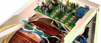
Manufacturing Guide
You can assemble a circuit using a light or sound indicator for your car at home. If you have experience in electrical engineering, this task will not take much time. But even if you have never done such work before, there is nothing difficult about it. The main thing is to correctly connect all the elements of the circuit and connect them to the on-board network.
Let's look at an example of assembling an indicator to determine the voltage of a car battery. Instead of the ten individual diode elements that are marked in the diagram, we will use a solid indicator since it does not take up much space.
What will you need?
What to prepare before starting the process:
- the circuit itself, in our example we use LM 3914;
- diode strip designed for 10 segments, you can use Kingbright DC-763HWA;
- power supply adjustable from 10 to 15 volts;
- resistors.
Stages
Let's briefly look at the instructions for making the device:
- First of all, the printed circuit board must be cleaned of dust. Make sure that this component is clean and there should be no signs of burning, otherwise this may lead to the device not working in the future.
- On a ready-to-use board, all components must be assembled in accordance with the diagram shown. To solder elements, use a soldering iron with consumables. Without exception, all components of the device must be fixed as firmly as possible. If the fastening of the resistors and diode strip is weak, then the structure may become loose over time as a result of vibrations, and accordingly, the performance of the device will be impaired.
- For greater convenience and to ensure a more compact assembly of the device, the right resistor element must be cut off.
- After all components on the board are installed, the system is configured. To do this, you need to apply a voltage of 10.5 volts to the board and adjust the right trimmer. You need to ensure that the first diode strip on the device turns on.
- Then you need to apply 15-volt voltage to the device and adjust the device so that the last strip on the board starts to light. Remember that not all strips should light up, but only one of them.
- Next, all you have to do is install the manufactured device in any place convenient for you and connect it to the on-board network. In particular, if you were making a device to determine the battery charge, then it would be better to connect it to a section of the circuit that is connected directly to the battery.
- To make sure that the device is functioning correctly, you need to use a multimeter to check the charge of the battery itself. Then compare these numbers with the division on the scale of the 10-segment indicator. If the battery charge is full, then the last bar should light up, if it’s medium, then the diode light in the middle of the indicator, and if the charge is minimal, then the first light.
Board for assembling the device
Price issue
If you want to install a voltage indicator in your car, you can buy a ready-made digital device. The cost of a more or less high-quality device will start from 250 rubles. On the market you can find options whose price is 1,500 thousand rubles, but such digital devices are additionally equipped with various regulators, for example, temperature in the cabin.
Working with a 220 V network
The simplest mains voltage indicator without a power source is made from a resistor, a current limiter (transistor), a rectifier (diode) and any LED. Resistor resistance is 100 - 150 kOhm.
Diode characteristics:
- current 10-100 mA;
- voltage 1-1.1 V;
- reverse voltage 30-75 V.
At 220 V, 3 Hz, the LED lights up. You can adjust the frequency and increase the brightness by changing the capacitance of the capacitor. Such an indicator operates at a minimum voltage of 4.5 V. In addition to the mains current, it can determine the serviceability, on and off state of an electrical appliance.
DC Voltage Check
To check the 12-volt network and the integrity of the connections, you can make another LED indicator (you need 2 multi-colored LED elements). To limit the current, you can use a resistor with a resistance of 50-100 Ohms or an incandescent light bulb with low power. One of the LEDs lights up when a voltage of the appropriate polarity is connected.
You can add a capacitor, a diode and 2 transistors to a homemade indicator for a 12 V network. The field-effect transistor stabilizes the current. A capacitor that protects the diode from voltage surges is needed with a capacity of 0.1 μF, non-polar. A resistor with a resistance of 1 MΩ is the load of a bipolar transistor. When testing a constant voltage network, the diode checks the poles. If the current is alternating, this element cuts off the negative half. When voltage is applied, the current value is determined by the bipolar transistor and the resistance of the resistor (500-600 Ohms).
This device is suitable for working with alternating and constant voltage networks of 5-600 V.
Indicator for microcircuits - logic probe
Devices for indicating microcircuits are called logic probes. This indicator is three-level (3 LEDs are included in the circuit).
A logic probe allows you to:
- determine phase, short circuit, resistance of the electrical network;
- establish the presence of voltage 12 - 400 V;
- determine the poles for direct current;
- check the condition of diodes, transistors and other parts;
- determine the integrity of the electrical network by ringing;
- diagnose relay and coil breaks;
- ring chokes and motors;
- determine the terminals of transformers.
The power source is a 9 V battery. When the pins are closed, a current of 110 mA is consumed. After opening, no current is consumed; there is no need to install a switch or mode switch.
When checking a network with a resistance of 0 - 150 Ohms, 2 LEDs light up, and when the indicator increases, one LED lights up. At 220-380 volts the third one lights up, the rest flicker. If the circuit is broken, the LEDs will not light up. At zero on the contact 0.5 V, one transistor opens (KT315B), at 2.4 V - the second (KT203B).
It is possible to replace transistors with others having similar parameters.
Voltage indicator on two-color LED
Another simple indicator chip - with a two-color LED. Some home craftsmen use it to determine the operating mode of the lamp. For example, a basement light switch equipped with an indicator is mounted on a staircase. If it is on, the glow is red, after turning it off it is green.
Option for car
The circuit for indicating the battery charge and vehicle network voltage consists of:
- RGB LED;
- 3 zener diodes;
- 3 bipolar transistors (BC847C);
- 9 resistors;
The level is determined by color. Green glow at 12-14 V, blue at 11.5 V, red at 14.4 V).
If no errors were made when assembling the circuit, one of the resistors (2.2 kOhm) and the transistor (8.2 V) determine the minimum voltage limit. When the indicator decreases, the transistor corresponding to the blue glow connects the crystal.
If the voltage does not decrease or increase, the current passes through 2 resistors, a 5.6 V zener diode and an LED, a green glow appears (the transistors corresponding to red and blue turn off). When the voltage increases to 14.4 V, the red light comes on.
Option for car
A simple circuit for indicating the vehicle's on-board voltage and battery charge. The zener diode limits the battery current to 5V to power the logic chip.
Variable resistors allow you to set the voltage level to trigger the LEDs. It is better to carry out the setup from a network stabilized power source.
Sources used:
- https://svetilnik.info/svetodiody/indikator-napryazheniya-na-svetodiodah.html
- https://simplelight.info/raznoe/indikator-napryazheniya-na-svetodiodah.html
- https://svetodiodinfo.ru/texnicheskie-momenty/indikator-napryazheniya-na-svetodiodax.html
Indicator characteristics
Platform: MetaTrader4 Currency pairs: any Time frame: M5-M30 Trading time: any Indicator type: arrow Recommended trading centers: Alpari, Wforex, AMarkets
The developers of the SOLOMON trading system gave users the ability to customize the oscillators included in the trading system. The description in Russian will not cause problems with understanding the meanings of the parameter fields for traders who are familiar with Stochastic and RVI; others should definitely familiarize themselves with the principles of operation of these indicators.
The default presets assume a scalping type of trading on small timeframes with a large number of transactions. The trader can set up alerts for convenience and determine the size of the historical segment on which the arrow signals will be stored.
How the indicator works
The money management strategy of SOLOMON is based on a reverse transaction system - unprofitable or profitable positions are closed only after the appearance of the opposite signal (arrow). This allows the trader to avoid triggering stops when volatility jumps, but imposes an obligation not to trade at the time of news releases and during inactive periods of sessions (the so-called night trading - the transition period between the American and European sessions).
Positions are opened with market orders immediately after the arrow appears - it determines the direction and type of the transaction. Positions do not roll over overnight if the trader is not present at the terminal.
Purpose of elements and principle of operation of the circuit
Many readers have LED light switches installed in their homes. The LED backlight circuit looks like this:
- A chain consisting of a quenching resistor, an LED and a simple silicon diode is switched on parallel to the switch contact.
- When the switch is open, electric current flows through a quenching (current-limiting) resistor, back-to-back LEDs and an incandescent lamp.
- During one of the half-waves, when a positive voltage is applied to the anode of the LED, the light-emitting diode glows. This not only provides illumination of the switch, but also provides LED voltage indication.
If we remove the switch, light bulb and wires from the circuit, we are left with a chain consisting of a resistor and two diodes. This chain is the simplest indicator (pointer) of 220 V alternating current.
Let us dwell in more detail on the purpose of the circuit elements. We indicated above that the operating current of the signal LED is about 10-15 mA. It is clear that when a light-emitting diode is directly connected to a 220 V network, a current will flow through it many times greater than the maximum permissible value. In order to limit the current of the LED, a quenching resistor is connected in series with it. You can calculate the resistor value using the formula:
R = (U max – U led) / I led
In it:
- U max – maximum measured voltage;
- U led – voltage drop across the LED;
- I led – operating current of the light-emitting diode.
Having performed the simplest calculation, for a 240 V network we get the value of resistor R1 equal to 15-18 kOhm. For a 380 V network, you need to use a resistor with a resistance of 27 kOhm.
The silicon diode performs the function of overvoltage protection. If it is missing, with a negative half-wave U, the locked LED will drop 220 V or 380 V. Most light-emitting diodes are not designed for such reverse voltage. Because of this, breakdown of the pn junction of the LED may occur. When a silicon diode is connected back-to-back, during the negative half-wave it will be open and U on the LED will not exceed 0.7 V. The LED will be reliably protected from high reverse voltage.
Based on the considered circuit, you can make a voltage indicator of 220/380 V. It is enough to supplement the radio elements with two probes and place them in a suitable housing. To make the indicator body, a large marker or thick felt-tip pen is suitable. You can place radio components on a homemade printed circuit board or make connections using a hinged method.
A hole is made in the marker into which an LED is inserted. A metal probe is attached to one end of the body. A wire is passed through the second end of the housing, going to the second probe or an insulated alligator clip.
Despite the simplicity of the design, the device will allow you to check the presence of voltage at the output of a circuit breaker or in a socket, and find a blown fuse in the distribution board. Note that the above indicator diagram is also used in industrial products.
Option for car
Previously, in various “controls” of auto electricians, a low-power 12 Volt light bulb was used as an indicator. It was used to check the voltage in various parts of the vehicle's on-board network. Nowadays, most industrial and homemade 12V indicators use LEDs.
The design of such devices is practically no different from the first indicator considered. To convert the first indicator to 12 V, you need to eliminate the simple diode or replace it with a two-color LED. The quenching resistor at 12 V should have a resistance of 680 ohms.
This is how the use of LEDs in indicators for various purposes looks like. However, many other devices can be made based on LED, which will be simple, economical and reliable. Indicator and super-bright LEDs can be used to illuminate or illuminate various objects. Using LED as a voltage reference, a parametric voltage regulator can be built.
From the abundance of circuits for making a voltage indicator on LEDs with your own hands, you can choose the most optimal option. The indicator can be assembled in a couple of minutes from the most common radioelements.
All such circuits are divided into voltage indicators and current indicators according to their intended purpose.
What it is
An electrical tester is a device that is used to measure and determine the voltage in an electrical circuit. The main difference from a multimeter is the simplicity of the design and use of this unit; it operates quickly and can be used in any conditions.
Photo - resistance tester
There are also more compact probe testers that can be used to measure the voltage level in an outlet or any other electrical device, for example, generators in a car. They differ from standard indicators in their small size, and they also have simpler operating instructions.
Previously, a pointer tester, such as ASKOM, was mainly used. It has a reliable operating circuit, is powered by batteries and provides fairly reliable and accurate operation.
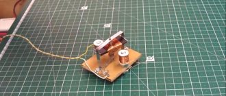
Homemade modification
If necessary, you can make an LED phase indicator yourself. First of all, a high-quality wire generator is selected for this. Its output voltage must be at least 12 V. You will also need a damper to assemble the device. There are different types on the market, and they vary quite a bit in sensitivity. If we consider a simple model, then it is more appropriate to select an element with a resistor. A microcontroller for the phase indicator will need a multi-channel type. At the end of the work, the LED is fixed, as well as the clamps.
DIY LED voltage indicator
Checking the voltage in the circuit is a procedure necessary when performing various types of work related to electricity. Some amateur electricians, and sometimes professionals, use a homemade “control” for this - a socket with a light bulb to which wires are connected.
Although this method is prohibited by the “Rules for the Safe Operation of Consumer Electrical Installations,” it is quite effective when used correctly. But still, for these purposes it is better to use LED identifiers - probes. You can buy them in a store, or you can make them yourself.
In this article we will tell you what these devices are needed for, what principle they work on, and how to make an LED voltage indicator with your own hands.
What is a logic probe used for?
This device is successfully used when it is necessary to perform a preliminary check of the operability of the elements of a simple electrical circuit, as well as for the initial diagnosis of simple devices - that is, in cases where high measurement accuracy is not required. Using a logic probe you can:
- Determine the presence of a voltage of 12 - 400 V in the electrical circuit.
- Determine the poles in a DC circuit.
- Check the condition of transistors, diodes and other electrical elements.
- Determine the phase conductor in the AC electrical circuit.
- Ring the electrical circuit to check its integrity.
The simplest and most reliable devices with which the above manipulations are performed are an indicator screwdriver and a sonic screwdriver.
Electrician's probe: principle of operation and manufacture
A simple identifier with two LEDs and a neon light bulb, which has received the name “arcashka” among electricians, despite its simple device, allows you to effectively determine the presence of a phase, resistance in an electrical circuit, and also detect a short circuit (short circuit) in the circuit. The universal electrician's tester is mainly used for:
- Diagnostics for broken coils and relays.
- Continuity checks of motors and chokes.
- Checking rectifier diodes.
- Definitions of terminals on transformers with multiple windings.
This is not a complete list of tasks that can be solved using a probe. But the above is enough to understand how useful this device is in the work of an electrician.
A regular battery with a voltage of 9 V is used as a power source for this device. When the tester probes are closed, the current consumption does not exceed 110 mA. If the probes are open, then the device does not consume electricity, so it does not need either a diagnostic mode switch or a power switch.
Main conclusions
They make their own indicators using simple schemes. No other expensive parts are required. To make a probe, you can use the body of a dried marker or a faulty mobile phone. A probe in the form of a pin can be placed on the front part, and a cable equipped with an alligator clip or probe can be placed on the end.
Category: Miscellaneous
Signal LEDs (in English literature - LED, light-emitting diode) consume a current of 10-15 mA. Depending on the color, the forward voltage drop across the light-emitting diode ranges from 1.5 to 2.5 V. The small size, low current consumption and low operating voltage of LEDs allow radio amateurs to make many useful devices.
Using a minimal set of parts, you can make an LED voltage indicator with your own hands.
Using Voltage Indicators
The use of indicator screwdrivers makes it possible to find the phase wire, neutral and ground in sockets, switches, lighting fixtures, verify the presence of voltage in the electrical network, identify voltage breakdowns on the body of household appliances, and also detect wiring in the walls under tiles or a layer of plaster with a finishing finish coating. Work with testers begins after their verification. The test is performed on a stressed area. Its presence on the network will be indicated by a light signal from a neon or LED indicator lamp. After checking the suitability of the device, breakdowns and malfunctions of electrical networks, household appliances, and lighting devices are eliminated. The main types of work using voltage testers include:
- Searching for phase and zero is necessary if electrical wires are not marked. The work begins by turning off the circuit breaker on the input panel, from which the electrical network is supplied at the test site. After stripping the wires being tested and then separating them from each other to a safe distance, eliminating the possibility of a short circuit or electric shock to a person, they begin to identify the phase cable. If, after turning on the electric current and touching the voltage indicator to the stripped end of the wire, the lamp lights up, then this conductor is phase. The second wire is zero. If the indicator lamp does not light up, then the first conductor is without voltage. The second wire can be considered a phase, which must be verified using an indicator.
- Determining voltage leakage on the body of an electrical device involves simply touching the tip of an indicator screwdriver to its metal (unpainted) part. The appearance of a glowing lamp on the indicator after connecting the household appliance to the network indicates the presence of a phase on the device body, as well as the need to urgently eliminate this problem. The bright glow of the indicator screwdriver indicates direct contact of the phase conductor of the cable with the body of the electrical appliance, touching which can cause electric shock.
- Checking the quality of the conductivity of the circuit is carried out by touching the ends of the wire, stripped of insulation, to the tip and finger contact of the indicator. An audible signal or a glowing lamp indicates that there are no problems with the integrity of the conductor.
- Detection of hidden wiring in walls is based on the appearance of a light or sound signal from a voltage indicator in the area of the electromagnetic field created by a cable connected to the network power supply. Its boundaries will be determined by slowly moving an indicator screwdriver along the wall in different directions. The activation of a sound or light signal indicates the location of conductive wiring under a layer of plaster or finishing coating.
- Finding broken wires is based on the cessation of functioning of the indicator screwdrivers. In places of damage, the voltage probe will not light up or emit sound signals. His work will be stopped. The use of indicator screwdrivers is a prerequisite when carrying out voltage-related repair work. Their correct use is a guarantee of safety, eliminating the risk of electric shock.
What is the difference between N and PE wires in electrical wiring
According to modern requirements of the PUE, in addition to the phase and neutral wires, a yellow-green ground wire must also be supplied to the apartment.
The neutral N and grounding PE wires are connected to one grounded bus of the panel in the entrance of the house. But they perform different functions. The neutral wire is intended for electrical wiring, and the grounding wire is intended to protect people from electric shock and is connected to the housings of electrical appliances through the third contact of the electrical plug. If an insulation breakdown occurs and a phase gets into the body of an electrical device, then all the current will flow through the grounding wire, the fuse links will burn out or the circuit breaker will trip, and no person will be harmed.
If the electrical wiring is laid indoors with a cable without color marking, it is impossible to determine where the neutral conductor is and where the grounding conductor is, since the resistance between the wires is hundredths of an ohm. The only clue can be the fact that the neutral wire is inserted into the electric meter, and the grounding wire passes by the meter.
Attention! Touching exposed parts of a circuit connected to an electrical outlet may result in electric shock.
Why do you need a speed controller?
An engine speed controller, a frequency converter, is a device with a powerful transistor, which is necessary to invert the voltage, as well as to ensure smooth stopping and starting of an asynchronous motor using PWM. PWM – wide-pulse control of electrical devices. It is used to create a specific sinusoid of alternating and direct current.
Photo - a powerful regulator for an asynchronous motor
The simplest example of a converter is a conventional voltage stabilizer. But the device under discussion has a much wider range of operation and power.
Frequency converters are used in any device that is powered by electrical energy. Governors provide extremely precise electrical motor control so that engine speed can be adjusted up or down, maintaining revs at the desired level, and protecting instruments from sudden revving. In this case, the electric motor uses only the energy needed to operate, instead of running it at full power.
Photo – DC motor speed controller
Why do you need a speed controller for an asynchronous electric motor:
- To save energy. By controlling the speed of the motor, the smoothness of its start and stop, strength and speed, you can achieve significant savings in personal funds. As an example, reducing speed by 20% can result in energy savings of 50%.
- The frequency converter can be used to control process temperature, pressure or without the use of a separate controller;
- No additional controller required for soft start;
- Maintenance costs are significantly reduced.
The device is often used for a welding machine (mainly for semi-automatic machines), an electric stove, a number of household appliances (vacuum cleaner, sewing machine, radio, washing machine), home heater, various ship models, etc.
Photo – PWM speed controller
Operating principle of the detector
The operation of such devices is based on various physical effects. On this basis they are divided into types:
- electrostatic;
- recording electromagnetic radiation;
- metal detectors;
- combined (combine several techniques).
The first type reacts to a live wire. The action is based on the ability of a field-effect transistor to change the thickness of the pn junction and, as a result, conductivity when the gate leg enters an electrostatic field.
Advantages:
- Low cost.
- Simple scheme.
- Long-range action.
- There is no need to connect a load to the wire.
An electrostatic detector is indispensable if you need to find the location of a cable break. This is the most suitable option for home use.
Flaws:
- high sensitivity to electromagnetic interference from a router, microwave oven, TV, computer, etc.;
- inability to locate cables in damp walls;
- the device does not “see” de-energized lines.
By electromagnetic radiation
These seekers respond to the electromagnetic field generated by moving charge carriers. To generate current, a load is connected to the wire. For budget models, its minimum value is 1 kW, so it is impossible to find a lamp cable with such a device.
The advantage is high accuracy, the error does not exceed a few millimeters.
Based on the principle of a metal detector
The main working element of this device is an electric inductor coil that emits an alternating electromagnetic field. Based on the eddy currents induced by it, the device recognizes the presence of metal bodies in concrete or brickwork.
Advantage - the detector finds de-energized lines.
Flaws:
- complex device;
- high price;
- the same reaction to all metal objects - fittings, nails, pipes, etc.
Expensive metal detectors distinguish between copper, steel and aluminum.
The most functional models, in addition to the inductor, have an echo sounder, which allows them to identify wooden and plastic objects.
Detectors of this type are not used independently, because with their help it is impossible to distinguish the wire from the fittings. They complement the electrostatic or magnetic module and serve to clarify the data.
Probe indicators for searching for phase and zero
A device designed to find zero and phase is called an indicator. Light indicators for determining the phase on neon light bulbs are widely used. Low price, high reliability, long service life. Recently, LED indicators have also appeared. They are more expensive and require additional batteries.
On a neon light bulb
It is a dielectric case, inside of which there is a resistor and a neon light bulb. Touching the electrical wiring wires one by one with the screwdriver end of the indicator, you find the phase by the glow of the neon light bulb. If the light bulb lights up when touched, it means it is a phase wire. If it doesn't light up, it means it's a neutral wire.
Indicator housings come in different shapes and colors, but the filling is the same for all. To prevent an accidental short circuit, I advise you to put a tube made of insulating material on the screwdriver shaft. The indicator should not be used to unscrew or tighten the screws with great force. The indicator body is made of soft plastic, the screwdriver shaft is pressed in shallowly and the body breaks under heavy load.
Pros and cons of parallel LED connection
A big advantage of a parallel connection is that if the LEDs are connected correctly, if one of them burns out, the rest will work. The diodes will work if more LEDs burn out, the main rule here is that at least one branch should work. When LEDs are connected in series, failure of one of them will cause the row of series-connected chips to stop lighting.
A parallel connection allows you to connect two or more LEDs. Limitations can only arise in terms of battery power (power source) and the dimensions of the device itself in which you want to place your “brainchild”.
The disadvantage of parallel connection of LEDs is that the design becomes more expensive due to the fact that new elements appear in the circuit. As a result, the final product can be quite bulky.
It’s worth imagining a Christmas tree garland with such a connection of diodes... For it to work, you will have to connect another conductor to the LED-resistor pair. Therefore, 99.9% of all garlands are assembled from series-connected LEDs.
Why does the indicator light up when you touch the neutral wire?
I have been asked this question many times. One of the reasons is the incorrect use of the LED indicator. How to properly hold the LED probe indicator when searching for a phase is written in the article above.
The second possible reason for this behavior of the indicator is a break in the neutral wire. For example, a circuit breaker installed after the meter on the neutral wire tripped. In old apartments this is not uncommon and is a gross violation of the electrical wiring. It is imperative to remove the machine from the neutral wire or short-circuit its terminals with a jumper.
When the neutral wire breaks, a phase is supplied to it through devices connected to the electrical network, for example, through a switch backlight indicator, a TV in standby mode, any charger, a computer turned off only by the start button and other electrical appliances. The indicator shows this. In this case, the neutral wire can be dangerous and touching it is unacceptable. It is necessary to find and repair a break in the neutral wire, which may also be located in junction boxes.
Digital indicator screwdriver, with contact and non-contact voltage detection functions
This voltage indicator does not have any power supply.
On its body there is a window with a liquid crystal display, which displays digital voltage values of 12, 36, 55, 110, 220 Volts.
There are also two pole buttons. The first is designed for non-contact voltage measurement.
The second is for contact measurement.
The indicator has one working part, made in the form of a flat screwdriver.
Let's check the voltage indicator in operation
First of all, we will test the contact measurement method. We bring the indicator to the first, zero contact of the circuit breaker. A value of 55 V appears on the indicator display.
A small voltage may indeed be present on the neutral wire, but as a rule, it is only observed under loads (operating electrical equipment). Our machine was turned off at the time of measurements, that is, there was no actual load.
Now, bring the indicator to the phase contact.
The indicator clearly showed 110 Volts. The real voltage value of 220 V on the indicator display appeared barely visible.
Attempts to make the voltage indicator work in non-contact mode were unsuccessful, but a function not stated in the digital indicator’s instruction manual was identified: if you touch a phase without pressing the buttons, the indicator shows a barely visible lightning bolt on the display, indicating the presence of voltage.
Let us summarize the results of testing this voltage indicator:
Pros:
- does not have a power source;
- shows approximate digital voltage values.
Minuses:
- The non-contact voltage detection function declared by the manufacturer does not work;
- ambient temperature restrictions from -10 to +50 degrees Celsius;
- has limitations on the measured voltage of 250 V;
- According to the instructions, it is forbidden to touch two buttons at once ( probably it can give you an electric shock
).
We conclude:
This indicator is very unreliable in operation.
What is a logic probe used for?
This device is successfully used when it is necessary to perform a preliminary check of the operability of the elements of a simple electrical circuit, as well as for the initial diagnosis of simple devices - that is, in cases where high measurement accuracy is not required. Using a logic probe you can:
- Determine the presence of a voltage of 12 - 400 V in the electrical circuit.
- Determine the poles in a DC circuit.
- Check the condition of transistors, diodes and other electrical elements.
- Determine the phase conductor in the AC electrical circuit.
- Ring the electrical circuit to check its integrity.
Alternative connection type
Series-parallel connection of LEDs - found in floodlights and other powerful lamps operating on both direct and alternating voltage.
As you can see, the matrix is divided into branches, each of which has a current-limiting resistor. A specific copy is intended to replace the standard courtesy lamp in the car interior. If one diode fails, one circuit will stop lighting, and the remaining circuits will continue to glow.
If you can't decide whether to connect LEDs in series or parallel, there is an alternative option - a hybrid connection. At first glance, it is not clear what the point is.
The hybrid version takes advantage of the serial and parallel connection of LEDs. The circuit will work fully even if one of the elements in the circuit burns out, while at the same time the remaining elements will not experience overload. The voltage on each segment will be limited to the LED with the lowest drop.
To assemble the lamp correctly, and to ensure that the LEDs work for a long time and do not overheat, you need to decide how to connect the LEDs - in series or in parallel. You have become familiar with the strengths and weaknesses of each option. Thanks to the knowledge gained, you can repair an LED lamp or spotlight.
DIY voltage indicator circuits
The main function of a voltage indicator in everyday life is to determine the integrity of the electrical network. For a radio amateur, it is important to be able to determine the parameters and ring even non-working electrical appliances. You can make only the first type of indicators with your own hands. An experienced radio amateur can make an indicator that allows wires to ring.
In everyday life, homemade probes (controls) are often used, less often multimeters. The control is an incandescent light bulb in a socket; the wires act as probes. It allows you to not only determine the presence/absence of current, but also the voltage by the brightness of the glow. You can't do something similar with an LED lamp.
A multimeter allows you to determine all parameters at once, as it performs the functions of a voltmeter, ammeter and ohmmeter. They can determine the capacitance of capacitors and test transistors and diodes. Such a device cannot be made; it must be purchased.