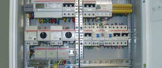
Features of electrical wiring installation
All electrical installation work is carried out only after installing the electrical panel and meter. After which the locations of the switching equipment are determined. In order to correctly lay wires and install socket boxes, an inspection of the cable route, conditions for laying wiring and electrical products is carried out.
The precision of electrification guarantees not only an aesthetic appearance, but also the safety of the entire home. So, when installing a socket box as a distribution box, you must follow the installation rules, these are:
- Fix the socket box in a wall made of brick, concrete, plasterboard using a building mixture.
- Install the socket box flush with the wall surface with the wiring closed.
- To fasten the glass, use special clamping screws with plates.
When laying the cable, you should use special fasteners that will protect it from mechanical damage and act as grounding. When designing an electrical network through sockets and switches, it is necessary to use only high-quality equipment.
Recently, installation socket boxes with a more in-depth shape have become in great demand, so that the stock of wires formed by loops or folds can fit compactly without sharp creases.
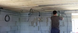
Product quality is the key to wiring reliability and functionality
The performance, safety and reliability of modern wiring depends on the accuracy, care and professional execution of electrical installation. In order to ensure uninterrupted electricity in a house or apartment, it is necessary to conduct a visual inspection of the electrical wiring and monitor the condition of household electrical equipment.
Wiring without junction boxes is the most modernized, reliable electrical system for modern apartments and houses. Its only drawback is the considerable consumption of cable products and all components. Cables, wires, sockets and switches must be purchased in specialized stores, where the products meet international standards for their intended purpose and have a quality certificate.
Any socket mechanisms, switches of the world's leading brands have high reliability and long service life with any connecting contact. Poor quality products lead to rapid wear and may cause short circuits, fires, or loss of power to a room or the entire house. When purchasing such products, information material from the manufacturer does not always provide a complete picture. Saving money is not a guarantee of safety, reliability and comfortable living.
Wiring connection methods
Bonding of electrical conductors in accordance with technical requirements and current instructions is carried out using soldering, crimping, crimping using appropriate tools. When choosing a contact connection method, it is necessary to consider what the fastening is for and where it will be placed.
At the points of connection and branching of wires, a reserve is always left for reconnection in the event of a malfunction. Today, the most versatile, efficient electrical connections are screwless terminals. Simple and convenient, suitable for all types of conductors of different cross-sectional diameters.
The clamp consists of a high-quality steel spring that is resistant to aggressive environments and a current bar made of electrolytic copper of special tinning, and is fixed on the contact area with a screwdriver. The terminal has no restrictions on currents and voltages; it even connects conductors to the sleeve. Meeting modern requirements, the clamp has a reduced size, due to which it does not take up much space in the electrical box.
Types of junction boxes
At the moment, the market offers a wide variety of junction boxes of a wide variety of designs and shapes.
Our article discusses only the box for connecting hidden wiring. Therefore, we will dwell in detail on products of this type.
So:
- First of all, all distribution boxes can be divided according to their shape. For hidden wiring, round ones are most often used. Their diameter and depth can vary greatly. So the diameter usually ranges from 60 to 100 mm, but the depth is usually from 30 to 50 mm. But if you have the right desire, you can find junction boxes for hidden wiring in other sizes.
- Square boxes are also widely used. Usually their sizes are comparable to those of round products. That is, starting from 60×60 mm and ending with products larger than 110 mm. The depth of square boxes usually does not exceed 30 - 50 mm.
- Rectangular junction boxes are also widely used. Here the range of sizes is even greater, but the total area is comparable to boxes of other shapes. Rectangular and square boxes for hidden wiring are used a little less frequently, although here it all depends on your wishes and technical conditions.
- In addition, junction boxes for hidden wiring differ in the material they are made of. According to clause 2.1.27 of the Electrical Installation Rules, they must be made of fireproof and non-combustible materials. When laying wires over combustible materials, metal junction boxes should be used. If the wire is laid using fireproof materials, then using fire-resistant plastic boxes is sufficient.
- If previously all distribution boxes were made hollow, now models with terminal blocks inside have appeared on the market. This allows for better connection of wires, and also helps to organize them inside the box. And although the price of such products is somewhat higher, their convenience is undeniable.
- Well, the last and very conditional division of distribution boxes is the presence of fastenings. It allows you to fix the products in the wall more efficiently and reliably, but if they are mounted on cement mortar, this advantage is very doubtful.
Methods for connecting wires in junction boxes
Putting the wires inside the box is half the battle. Now you need to choose a connection that is reliable and easy to maintain.
All cable line connections are divided into two main categories:
- Detachable, that is, the wiring can be disconnected and reconnected many times, without critical damage to the wire or connecting device. For example, a screw connection on terminal blocks.
- One-piece, that is, when the conductors are separated. the connection is destroyed. There is no big problem with this, it’s just that the cable gets shorter each time, and the connecting devices have to be purchased again.
The type of splicing when disconnecting boxes is selected based on the design of the overall network. If you plan to periodically disconnect one or two branches from a common box, it is better to choose a screw connection or reusable quick-release terminals.
For permanent connections that will not be dismantled for many years, the same terminals are used, only for one-time use. Despite the obvious drawback: the impossibility of reuse, such terminals provide more reliable contact compared to reusable ones.
If you use only copper conductor both in the backbone network and in subscriber branches, there are cheaper ways to permanently connect the wires:
- Twisting with welding.
Creates reliable contact, without the risk of sparking and heating of the wiring under heavy load. The connection is simple, but requires special equipment. As a last resort. You can melt the copper tips with a portable gas torch. - Twisting with soldering.
It is not as reliable as with tip reflow, but when using refractory solders, the connection practically does not lose strength, even when heated. The advantage is accessibility. A powerful soldering iron is easier to find than welding equipment. The basic rule: strength is ensured by twisting; we simply fill the voids with solder, improving contact. - Twisting with mechanical fixation (crimping). A questionable method, since there is a possibility of damage to current-carrying wires.
- There is nothing to say about ordinary twisting: although it is not prohibited, this technique is practically not used.
Direct connection (disconnection)
Is it possible to organize electrical wiring without junction boxes? When branching no more than 2 lines, it’s easy. Several conditions must be met:
- If the connection is made by twisting, soldering with refractory solder is required. Crimping can be used.
- "T" shaped connections are undesirable; it is better to make a "Y" shaped branch.
- After connecting and checking the quality of contact, the splice area must be carefully insulated and protected from moisture. Especially if the connection is made in hidden wiring (plaster wall) or on the street.
Advantages and disadvantages of installation without junction boxes
The advantages of the method without branch boxes are:
- Reducing contact connections, which reduces the likelihood of emergency situations;
- Reduced labor costs at the installation stage;
- Simplicity of the connection diagram; in the absence of multiple ends in junction boxes, the likelihood of connection errors is reduced;
- For customers, reducing wiring elements, in this case junction boxes, reduces the cost of work.
- Improving the interior of the premises;
- During maintenance and repair, there is no need to destroy decorative elements on the upper sections of the walls.
The disadvantages include the following:
- Non-standard connections make it difficult to repair and maintain wiring by electricians who did not participate in the installation process;
- An increase in the number of groups, and therefore more wires. This statement is controversial; wires from boxes to sockets are excluded, so the difference in the length of the wires consumed is not significant.
- In some sections it is necessary to remove the outer sheath of the cable from the wires, as a result of which the double insulation element is missing.
In what cases do they prefer to use installation without junction boxes?
The main argument that attracts customers to use this technique is the absence of distribution boxes on the top of the walls. It is believed that they spoil the appearance of the interior; covers do not always fit into the picture of the overall design. If they are covered with wallpaper or plaster, in the event of a fault in the network, eliminating them requires the destruction of individual sections.
When opening the box, it becomes necessary to tear off part of the wallpaper or destroy the plaster coating, plaster molding and other interior elements. In essence, this leads to large-scale repairs, which require considerable labor and money.
To get rid of the prospect of destruction of the results of expensive repairs, they resort to methods of installing electrical wiring without the use of junction boxes.
Connecting wires in a socket box
Features of installation of lighting networks without branch boxes
As in socket groups, the goal of the technique is to reduce contacts, labor costs and increase reliability. It is possible to use two-wire wires for single-key switches, but it is recommended to lay a cable with three wires. This is due to the fact that modern chandeliers and lamps have a terminal for the grounding wire on the body; it is better to comply with all safety requirements.
Network connection with single-key and two-key switches
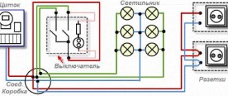
For a better understanding, using a simplified diagram, we will consider connection methods: from the distribution board to the nearest switch we lay a phase wire, pull the neutral and grounding conductors to the lighting fixture. The grounding is attached to the lamp body, N is the neutral wire to the contact of the lamp socket.
The phase wire is fixed to the incoming contact of the switch, and a conductor is laid from the output contact to the free contact of the lamp socket. All the technology is not tricky, there is a complete absence of unnecessary contacts and junction boxes. If there are several elements in the lighting group in different rooms, we make connections in the box of the first switch and lay the line further. As in socket groups, connections can be made at the switch terminals. In the classic version, the contacts are twisted, insulated, and packaged at the bottom of the switch housing box.
The diagram shows the connection of single-key and two-key switches in one group.
Connecting sockets
The sockets are connected using three wires: phase, neutral (zero) and ground. The connection of the phase and neutral conductors can be connected in two ways: with and without a line break. In the first case, the wire at the connection point is bent and disconnected. Both ends are stripped of insulation and made into one contact. In the second case, the wire is not disconnected; a loop is made, which is stripped of insulation and clamped with a screw. The advantage of this method is that if the contact in one socket loosens, it does not disappear in the others and they remain in working order. The grounding wire can only be connected without breaking the line.
The order of connecting sockets is as follows:
- One common cable of the group from the distribution panel is laid in a common groove (or in the floors).
- At branching points, the cable is lowered (or raised) directly into the first socket of the group.
- Each subsequent outlet of the group is powered from the previous one.
Installation diagram
What is a junction box
From the electrical panel, the wires disperse throughout the rooms in the house or apartment. Each room, as a rule, has more than one connection point: there are several sockets and a switch. To standardize the methods of connecting wires and collect them in one place, distribution boxes are used (they are also sometimes called branch boxes or junction boxes). They contain cables from all connected devices, the connection of which occurs inside the hollow housing.
In order not to look for wiring during the next repair, it is laid according to certain rules that are prescribed in the PUE - Rules for the Construction of Electrical Installations.
Electrical wiring rules
One recommendation is to carry out all connections and branch wires in the junction box. Therefore, the wires are run along the top of the wall, at a distance of 15 cm from the ceiling level. Having reached the branch point, the cable is lowered vertically down. A distribution box is installed at the branch point. It is where all the wires are connected according to the required circuit.
According to the type of installation, junction boxes are either internal (for hidden installation) or external. Under the internal ones, a hole is made in the wall into which the box is built. With this installation, the cover is flush with the finishing material. Sometimes during the renovation process it is covered with finishing materials. However, such installation is not always possible: the thickness of the walls or finishing does not allow it. Then a box for external mounting is used, which is attached directly to the wall surface.
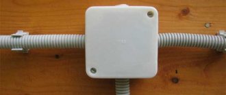
Some forms of junction boxes
The shape of the junction box can be round or rectangular. There are usually four conclusions, but there may be more. The terminals have threads or fittings to which it is convenient to attach a corrugated hose. After all, it is more convenient to lay wires in a corrugated hose or plastic pipe. In this case, replacing the damaged cable will be very simple. First, disconnect it in the distribution box, then from the consumer (socket or switch), pull it and pull it out. Tighten a new one in its place. If you lay it the old fashioned way - in a groove, which is then covered with plaster - you will have to drill into the wall to replace the cable. So this is the recommendation of the PUE, which is definitely worth listening to.
What do distribution boxes generally provide:
- Increased maintainability of the power supply system. Since all connections are accessible, it is easy to determine the area of damage. If the conductors are laid in cable channels (corrugated hoses or pipes), replacing the damaged section will be easy.
- Most electrical problems arise in the connections, and with this installation option they can be inspected periodically.
- Installing distribution boxes increases the level of fire safety: all potentially dangerous places are located in certain places.
- Requires less money and labor than laying cables to each outlet.
Technical solutions for wiring without junction boxes
In some cases, the PUE even requires doing exactly this; it is prohibited to enter into the distribution box and make branches from the lines that power electric stoves, heating boilers, air conditioners and other devices that consume large amounts of electricity. For them, a dedicated circuit breaker is installed in the distribution boards, from which its own cable line is laid; this entire circuit is a separate group.
Sockets in a circuit without distribution boxes can be connected in parallel in the circuit of one group. As practice shows, no more than 8 pieces per line, maybe even less. The quantity depends on the specific conditions of the facility and requires an individual calculation, taking into account the power of electrical household appliances that will be connected to sockets in this group.
Difficulty finding a junction box
Distribution boxes are designed to branch one power cable entering a room into many electrical points. Therefore, when installing new wiring or adding sockets and switches, you will have to find out where the distribution nodes are located.
Location of distribution boxes and sockets
When looking for a distribution box in a panel house, people face two problems:
- The box is not visible. It is hidden in the thickness of the wall. During repairs, the specialist makes every effort to ensure that this unit is as inconspicuous as possible and hidden under the plaster.
- To connect new wires, the box must be opened. This should be done with maximum accuracy down to one centimeter. Therefore, you will have to determine the shape and dimensions of the box before opening it. Nobody wants to spoil walls and wallpaper. You need to open the box as carefully and competently as possible.
Important. You need to know how many boxes there should be in a room
Some projects involve the presence of two distribution points in one room. In other cases, the box is through. With this design, it is one for two rooms.
Installation of wiring without junction boxes, save or lose
Good day, dear blog readers. The topic of this post will be installation of wiring without junction boxes and whether to do so or not.
Content
hide
1 Electrical installation with junction boxes
2 Electrical installation without junction boxes
3 We recommend reading:
I won’t say that often, but still this topic arises. The distribution box, as you know, is designed to connect power wires with wires going to sockets, switches, lamps, and so on.
The more connections, the larger the box can be and of course they should be installed so that they are accessible. Nobody wants to see box lids under the ceiling against the backdrop of expensive and beautiful wallpaper. And whatever one may say, the boxes end up under wallpaper or a layer of plaster, perhaps even a thick one if the electrician installed them before the plaster.
The question arises, is there a way out? It turns out there is, and let’s talk about it.
Electrical installation with junction boxes
Any electrical circuit in any room of our apartment consists of one or two switches, several sockets, lamps depending on the structure of the ceiling and, of course, several junction boxes.
In this case, the power wire comes from the machine located in the panel to the distribution box for lighting, and from it to the switch and to the chandelier or lamps, this concerns lighting. With sockets it’s almost the same, the power wire comes from the same panel, of course from another machine, into the distribution box of the socket group, where it is connected to the wires going to each of the sockets, let’s say there are three of them in the room.
The sockets, of course, can be spaced apart and then it makes sense to add another intermediate box. That is, in one outlet box the supply wire from the panel is connected, the wire going to the outlet and the supply wire to the intermediate box, in which it is connected to two wires going to the two remaining outlets. Usually this wiring option is used, but it should be noted that the connections in the box must be of high quality and correct, and of course there must be easy access.
Of course, I don’t want to bother with boxes, I want a minimum of connections, less dust, and sometimes the customer thinks that if he refuses distribution boxes, he will save on their cost and on the price for their installation.
Electrical installation without junction boxes
Let's look at an option that is also used for electrical installation, which in general is not prohibited, without the use of junction boxes. Let's imagine the same option with three sockets. The power is also taken from the panel from the machine and comes to the first socket and then through a cable to the second and third.
Now more details. We begin to cut the wire that comes into the first socket, that is, a three-wire cable in which there is a zero phase and grounding, and if we can break the neutral and phase wires, then the grounding wire is not supposed to be interrupted and it should reach this way without breaking to the grounding contacts of the third socket.
The stripped wires, neutral and phase, are connected to the corresponding incoming contacts of the socket, then the phase and neutral wires are stripped, which will go in a loop to the second socket, connected to the output contact and tightened well using a normal screwdriver. Naturally, in one contact there is the input and output of the neutral wire, and in the second contact there is the input and output of the phase wires.
You will have to tinker with the grounding, you can’t break it and naturally you can’t push it into the input and output of the contact group in the socket, so we strip the grounding wire, bend the exposed section of the wire in half and get two wires in contact with each other with an undivided core.
Then a piece of wire is taken, stripped on both sides, one end is attached to the bent bare ground wires and the resulting three bare sections are crimped with a sleeve for crimping wires, insulated, and the second stripped end of the wire is inserted into the ground contact of the socket and clamped well.
In this case, we get a non-breaking ground, and a separate branch as prescribed in clause 1.7.144 of the Electrical Installation Rules (Electrical Installation Rules) for PE (grounding conductors).
Next, we send the cable in the groove to the second outlet and then to the third. In this option, we interrupt the zero and phase, and use the contacts of the socket as a terminal block, but it’s good if the socket is branded and the contact group is powerful and of high quality.
Imagine a cheaper outlet, what contacts does it have? During operation, the contacts, if they are weak, can heat up; as the contacts cool down, they weaken and the wire may fall out of the contact or even burn out, then there will be no power in all other sockets. Often during installation, no matter what goes wrong with the laying of the wire, they cut through not only the zero and phase, but also the ground wire, in which case if for some reason the ground wire jumps out of the contact group and a current leak occurs, your ouzo, if you installed it , is unlikely to work. Remember this.
We can go even further. Crimping wires and making taps not only from grounding, but also making taps and crimping phase and neutral wires. Naturally, the sleeves for crimping are insulated, placed in the socket box, and the taps are connected to the corresponding contacts of the socket, which is installed in the socket box. In this case, the socket box also serves as a junction box; for greater convenience, longer socket boxes can be used, and all connections are available for preventive maintenance.
But in this installation option, the wire consumption is much greater, and when installers say that the wire consumption is almost the same, they are simply lying. So, decide for yourself what is easier, more profitable and more economical for you. Happy installation!
Best regards, Alexander & Igor.
Installation of junction boxes
As already indicated, junction boxes refer to additional protection of the indoor energy system. They are installed on any branches from the main highway. When laying electrical wiring, it is necessary to ensure that connections and current-carrying conductors do not touch the ceiling, floor and walls of the room. This condition is met due to the insulation of electrical wiring and the installation of junction boxes. To connect wires, soldering using solder and flux was previously widely used, but today reliable contact is ensured by twisting the wires and using screw terminal blocks to crimp them. However, it is necessary that the connection is not accessible and there is no open contact with the enclosing structure. It is these conditions that are provided by junction boxes. There are no restrictions on the number of boxes that can be installed in a room; you just need to proceed from the economic side and common sense. There are only some restrictions on the installation location. For example, in bathrooms, it is prohibited to install junction boxes closer than sixty centimeters from the bathtub or shower tray and below three meters from the floor level. As a rule, for safety reasons, junction boxes are installed outside these premises. Today, the following types of junction boxes are widely used:
- Junction boxes for internal installation - used when installing hidden electrical wiring;
- Open installation junction boxes - used when installing external or open wiring. Sometimes they are also called “overlay boxes”.
The main requirement for the installation of junction boxes is subsequent convenient maintenance and access. It is necessary to avoid situations where, in order to carry out work in the junction box, it is necessary to dismantle or destroy finishing or decorative elements.
Design Features
Installing electrical wiring without junction boxes is a technique that has appeared relatively recently. Despite this, in some cases this installation scheme does not contradict the basic documents of PTEEP and PUE. At the same time, the method itself still causes controversy in professional circles.
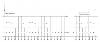
In this case, the wiring diagram has some differences from the one used when installing junction boxes. Without distribution boxes, the electrical wiring is also powered from a switchboard with an automatic circuit breaker. From it the wire is directed to the first socket and then stretches in a loop to the others.
The three-core cable (neutral, phase and ground) suitable for the first outlet is cut. Zero and phase are broken. But the grounding cannot be interrupted; it must reach the contacts of the third socket. Therefore, the two stripped wires must be connected to the corresponding incoming contacts. Then the zero and phase are sent in a loop to the next socket, connecting and tightening well with a screwdriver at the input contact.
In this case, the grounding cable is stripped. The cleaned wire is bent in half. Thus, we get two wires in contact with each other, which have a common core.
After this, a piece of wire is stripped on both sides. One end must be attached to the bent ground. As a result, we get three bare areas, which we press with a special sleeve and insulate. We bring the second end to the contact of the socket intended for grounding and clamp it. Thus, we avoid gaps and fulfill everything according to the documentation requirements.
After this, we connect the wire through the groove to subsequent sockets. In this case, a phase interruption and zero occurs. Terminal blocks are used to secure them.
It is worth noting that such installation of electrical wiring can cause some difficulties when using cheap sockets. Such products often have weak contacts. Because of this, the wires in them can become very hot, causing the wiring to burn out or cause a fire. Also, the ends of the cables may fall out of the contacts, leading to disruption of the power supply circuit in other outlets.
To avoid a similar situation with such a wiring installation scheme, the grounding wire (both zero and phase) is cut through. In addition, you can crimp cables, making taps not only for grounding, but also for phase and neutral. In this case, the sleeves used for crimping must be insulated. They are placed in the socket box, and the taps are then connected to similar contacts.
In the described wiring diagram, the socket box will serve as a distribution box. Therefore, the use of junction boxes will not be carried out here.
In order for such installation to take place quickly and without problems, experts recommend buying socket boxes that are longer. This way they will fit all the necessary wires.
For branch circuits, you need to consult an electrician before installing them yourself. However, you need to know that installing cables in this way is used in certain cases.
Bolted connections
Bolted connection
This connection is quite reliable, but cumbersome. It is not suitable for modern distribution boxes due to its dimensions, but for large old-style boxes it is just right. This method can be used to connect both homogeneous and dissimilar metals. The work is carried out as follows:
- A steel washer is placed on the bolt.
- The insulation is removed from the conductors and they are formed into a ring.
- The first ring is put on the bolt.
- Then comes another steel washer, which is placed on the bolt after the first.
- The second connecting wire is put on top.
- This entire “sandwich” is clamped with a nut.
- In the end, everything needs to be insulated.
It is this design that makes the contact bulky. If you need to connect several pairs of wires, then this option will not be the best.
Where and how to install distribution boxes
Usually the boxes are located under the ceiling at a distance of 100-200 mm from it. The specific value depends on the height of the room. If the wiring is hidden, then the product is placed inside the wall to a certain depth so that the surface of the cover is flush with the wall. For open-type electrical wiring, external boxes are suitable.
In accordance with the rules for the construction of electrical installations (PUE), it is important to provide free access to the junction box cover, which is necessary in case of inspection or troubleshooting. If the product is external and attached directly to the wall, then this condition is met automatically
When placing the device in a wall recess, two requirements must be met. Firstly, you need to know where it is installed, and secondly, you should ensure timely access to the product without compromising its aesthetics. If the latter can be neglected without violating the PUE, then the first requirement is mandatory and important.
You can maintain an aesthetic appearance by gluing beautiful wallpaper, and then carefully trim around the lid of the junction box without removing the part that is glued to it. When choosing alternative finishes, make sure that the color of the surface of the lid and the wall are identical. Try to make sure that if you need to remove the cover, the wall in this place does not collapse. If suspended ceilings are installed, then small hatches should be created to provide access to the boxes.
Electrical Wiring Safety
Upon completion of the installation of electrical wiring, it is necessary to carry out a set of measurements to ensure that the system is ready to use modern household equipment and appliances. Checking the functionality of the electrical panel, wires, cables, sockets, switches makes it possible to correct mistakes in a timely manner. Testing shows that:
- electrical wiring contacts have reliable grounding;
- connections are correctly connected;
- there is no extraneous voltage or damage to the insulation;
- automatic protection device matches the wiring.
Accurate measurements of electrical wiring can only be carried out with the help of electrical laboratory specialists. For testing, control and measuring equipment is used, which shows losses and electricity consumption. Sockets, switches, and lamps especially require preventive inspection to avoid short circuits.
Junction box installation technology
So, let's talk directly about the process of installing and connecting the distribution junction box. If we talk about installing the box itself, there is nothing complicated or problematic here. Built-in versions of boxes are built into the walls, and overhead boxes are attached to the walls with dowels or self-tapping screws. Installation of a built-in box is more complex and time-consuming; in this case, it involves the creation of a special landing niche. In one of the walls, closer to the ceiling, it is necessary to make a niche of the appropriate size, this is where the box will be installed and secured with alabaster or cement mortar.
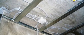
However, these procedures refer to the final stage of work. First of all, you should create a “network” of grooves - channels through which cables will be connected to the distribution box. The required number of drops to switch boxes and sockets must be in a strictly vertical position. In order to lay cables horizontally, it is recommended to take advantage of the gaps between the floor slabs and the walls.
After completing the preparation of the grooves and installation of the socket boxes, we proceed directly to the electrical wiring arrangement - an important part of this process will be the installation and connection of the distribution box. Often the process of connecting wires inside the junction box causes certain difficulties
To avoid them, we recommend marking each end of the cable in one way or another. For example, we connect the wire that supplies power from the electrical panel - we mark it with the appropriate word, we connect the cable from the socket block - the same thing, etc. Each individual electrical circuit that we connect to the distribution box must be labeled accordingly, in this case we will not face confusion later
Often the process of connecting wires inside a distribution box causes certain difficulties. To avoid them, we recommend marking each end of the cable in one way or another. For example, we connect the wire that supplies power from the electrical panel - we mark it with the appropriate word, we connect the cable from the socket block - the same thing, etc. Each individual electrical circuit that we connect to the distribution box must be labeled accordingly, in this case we will not face confusion later.
Cable cross-section
Now let’s take a break from the distribution box for a couple of minutes and say a few words about the cable cross-sections that are used when wiring a house or apartment. It is known that voltage is supplied to rooms from the electrical panel, as a rule, using a three or two-core cable with a cross-section of at least 4 square millimeters. This cross-section allows the cable to easily withstand any powerful power consumers. To connect sockets, cables with a cross-section of 2.5 square millimeters are used, and for a lighting system, a cross-section of one and a half square is sufficient.
Down with junction boxes. Installation in socket boxes.
I’m touching on a very brutal topic that I’ve been using for a long time, and because of which there are a lot of debates about the professionalism of some electricians and electricians. Namely, installation of apartment electrics without junction boxes. What is a junction box and why was it needed and where did it come from? Yes, it’s simple: so that you can conveniently connect different cables there! Let's say you need to branch one cable into several others - you put up a neat box, make a connection there, and rejoice. Yes, here’s an example: you need to connect a lamp, a switch and a light power cable from the panel. Which means we need desoldering!
However, in practice it turns out not so beautiful and smooth. The fact is that the Rules have one brutal point: there must be access to ANY such box (or rather, connection)! This means that, say, if at three o’clock in the morning you want to look at how your twisting of aluminum and copper is doing, you just open the box and look.
Let me add: actually, why this post? I'm tired of writing in the comments about how this is done (in relation to light distribution). And, since I am ONLY assembling shields, I am asked to explain how my designed cables should be laid and connected. Now I can link to the post and say “show this to your electrician.” Let's increase the literacy level of the population!
Now I will write down a list of different theses that relate to the installation of apartment electrics. And you decide which ones you like.
- If we use junction boxes, then we are obliged to provide access to them. And not at all in the form of “Yes, I have a lid under the wallpaper - if I need it, I’ll cut through it and open it.” If your electrician says he uses desoldering, check how he does it. Boxes under suspended-stretch ceilings also apply to this.
- With proper design of the panel (which is what I am doing now), wiring is not needed at all due to the fact that the lines are laid either in such a way that all connections are made behind the mechanisms of socket-switches, or there are no connections at all. For example, this includes laying separate lines for stationary equipment (washing machines, air conditioners, heated floors, etc.) - such lines either end with a single socket, or the cable goes directly into the equipment.
- Typically, using pinouts involves a different way of thinking when routing cables. The topology becomes like a web, which is then difficult to trace and ring the lines if you don’t know that there is a wiring somewhere and it’s somehow cleverly connected.
- Wiring is good for any facility where special places are intended for cable routes: collapsible ceilings, niches, or where the wiring is mounted openly. In this case, there are no problems with access and, as a rule, with the appearance of the wiring.
But what are we doing? Electricity in residential premises, and mainly in apartments, houses and cottages. And that’s why appearance and design come to the fore. This means we need to get rid of the soldering. And if they are needed, you need to think about how and where to do them so that the main condition is preserved: to provide quick access to connections.
Note! Even if you move the switch to another place, “multiply” the socket, you are still required to do the wiring on the old connection. If your electrician is trying to bury a connection in the plaster and doesn’t even try to provide access to it, kick him right away!
Well, for those who have to do wiring, I will offer several options for their placement, which you don’t always have time to think about. But I’ll warn you in advance. There will inevitably be some play on words and substitution of terms due to the fact that I started talking about the junction box as a separate entity, an independent unit, and end with a more general one, meaning “a place where you can make wire connections.”
So, you can:
- Really fuck up a separate junction box. If it's in the wall, it means hello, there's a cover on top of the wallpaper. As a last resort - right under the wallpaper, so you can feel and dig it out. If it is overhead, it could be a plumbing cabinet (various automation switching, DUP bus, etc.) or something somewhere under the kitchen, if, for example, they forgot to make a cable for the oven and it needs to be branched off from the hob cable (with appropriate protection) ;
- Use the socket box and the free space BEHIND the switch or socket mechanism. This method is the most progressive and, as it turns out later in the article, covers almost all the tasks that arise during electrical wiring;
- Use a DEEP socket box! Not everyone knows they exist! This type of socket box is almost twice as deep as a regular one. This is useful if there are a lot of connections in such a wiring, and the wall allows you to install such a socket box in it.
- Use one of the socket boxes in the socket block. But do not install the mechanism, but close it with a standard plug from a series of sockets. This allows for affordable full wiring, but it will fit into the design of the socket block.
- Use standard terminals of the mechanisms if they support switching of several wires. These are, for example, all sorts of underfloor heating controllers that have 4 terminals: Input L, Input N, Output L, Output N. There, each wire is screwed into its own screw, and no external connections are required.
We are progressive people, and today we will analyze the option of complete installation without junction boxes. What is professionalism here, and where is the brain required? And here's where:
- It is necessary to correctly design the cable lines in such a way that all of them can be connected locally in the socket boxes without any branches or unnecessary connections. This is precisely one of the points for assembling a custom-made shield. In most options, the following results: lighting - its own line for each room; general purpose sockets - their own line for each room; powerful and/or stationary equipment - its own line for each equipment in each room.
- It is necessary to think through the routing of the lines so that all the cables go where they need to and go sequentially one after another. This especially applies to all walk-through switches and lighting control in general;
- Do not forget to remember that some mechanisms such as dimmers are thicker, and they may require a recessed socket box (if this is technically possible due to the type of wall).
Let's see how such an installation will look in practice.
Installation of power lines of sockets
This point should immediately begin with a long debate about the continuity of PE. What's the trick there? The trick is this. PE is the most important conductor: protective. Protection Earth. Some people call it “grounding” in the old fashioned way, but this is not entirely correct now. Because depending on the type of power supply system, PE will be either grounding (TT), or grounding, and then repeated (TN-CS). Therefore, it’s easier, more accurate and concise to write “PE” and not worry about it.
This conductor protects a person from coming under dangerous voltage on the device body if something happens inside the device. It is with the help of this conductor that the RCD works (we are preparing about the RCD). And the most important thing is that this conductor is always CONNECTED. And it had reliable electrical contact. Otherwise, someone might get killed. And in the worst case - en masse - due to the fact that the casings of all devices are connected to PE and dangerous potential can appear on all of them at once.
And the problem is that if a phase or zero comes off (or there is poor contact), you will immediately know, because the electricity will disappear or the voltage will float. And with PE, only the popular measure in our country “Until thunder strikes, a man will not cross himself” works. That is, until there is dangerous voltage on the housing (and the protection works or does not work) or until someone specifically checks with instruments, we will not know the state of PE.
And one of the measures that allows you to increase the reliability of the protection (and the PE contact in particular) is to screw it very tightly and make sure that it is not accidentally unscrewed or disconnected. That is why all PE busbars have a bunch of bolts, and that is why each PE must be screwed with a separate bolt/screw. Imagine what will happen if there are several different PEs under one bolt? You unscrewed the bolt to disconnect one wire. And while they unscrewed it, it was crazy. And just to another PE line, which is a miracle! – I accidentally ended up on the same bolt.
And, as a particular requirement based on this measure, a certain point of rules emerges, saying that, they say, all PE connections must be made in a non-separable way. Or so that they cannot be disassembled without a special tool. And when it comes to connecting sockets, shit begins to boil over on the Internet.
Power sockets are wired in two ways: star and cable. The star immediately implies the creation of a junction box where the supply cable and all cables from sockets or socket blocks are brought together. I remind you the following:
- Do not forget that the wiring for the star can fit in a deep socket;
- There is no need to interpret the star as a parallel connection of 5 sockets of 16A each and run a 4-square power cable to the panel and put 25A on it. The socket is a maximum of 16 A. Period!
The train is a simpler and more visual thing. It is much more convenient to make and requires less cable. And the line tracing is clear: from the panel to the first block of sockets. From the first block to the second. From the second to the third and so on.
But the same question about the continuity of PE immediately arises. What should I do? And how to interpret the clause of the rules? If in a star we have our own PE from almost every outlet, then we have one PE for everyone. The specialists were divided into two groups.
- The first group believes that if you assemble a cable on sockets, using the opportunity to push two wires into one contact at once (provided by the manufacturer), then the requirement is met. In our case, each socket contact is a type of screw terminal block. Three wires: socket contact (already connected at the factory) and incoming and outgoing. Voila. A screwdriver is a special tool. And you get a real branch from the main line. I think so too, and I don’t see anything wrong with that if you use high-quality sockets and carry out the correct installation. And if you check your installation. Let's say, in the very last socket, connect N and PE - the RCD should trip. And while the line is being repaired, turn it off in the control panel. Agree - you rarely open sockets in your apartment.
- The second group believes that PE should, in any case, be a solid main line, and each outlet should have its own branch from the main line. She is more right, but she does not offer a specific installation method. Someone immediately remembers the wiring and hangs them on everything and everywhere (on the forums there were posts like “Yes, I’m making a hidden wiring under each block of sockets!”). Someone invents a clever way of laying the cable so that it REALLY runs without breaking, but has an exact margin in length so that at each socket of the block it is possible to slightly remove the cable insulation without cutting the wires, bend the wire in a U-shape and push it into the socket. Oh, poor sockets!
Now I’ll show you how it all looks in practice and show you one of the options that allows you to kill two birds with one stone: convert any cable wiring into a continuous branch, or immediately install a continuous branch. The trick of this option is that the cables are laid in the same way: both for the cable and for the continuous wiring! This means you don’t have to turn on your brain on purpose, don’t think about it and, therefore, work without dullness, according to a proven scheme.
So, let's look at how a regular blunt loop is made. And at the same time, how to push the socket into the socket box. And then some asked how long the ends should be left and how to bend them so that they do not get in the way.
I took the board, went to the market to a guy I knew and stole some PUNP and socket boxes from him for experiments. We lay pieces of the “cable”: the one coming from the shield to the left. And a piece between the socket blocks:
Well, we also need cuttings of the same cable for jumpers between the sockets of the blocks. I did this: I measured the cable with a margin of about each block. And then I used the same cuttings of the same cable for jumpers. This feature is even useful in that if the connections are made by different craftsmen (and if the cable trimmings after the repair are already in the trash), they will still be able to find the cable.
Let's push everything into the socket and screw it on:
That's all. All that remains is to repeat this miracle of technology for each outlet. It will turn out like this:
Now let's put the socket in the socket box. I made the tails too long here. Their length should be such that the lower edge of the socket frame touches the edge of the socket box. First, we bend the tails directly behind the rear of the socket:
Then we bend them again and push in the socket:
As a result, we will get something like this:
I remind you about the UNICA series. I love it for this Z-shaped groove on the frames (and for the thickness of the frames). Even an ass-drunk electrician can assemble this socket block
Here! This is all good, of course! Well, now let's get down to perversions. Let's turn our stupid cable routing into a real branch, and a non-breaking one at that! A little shamanic magic is needed here. Namely – CASES!
I will immediately write two theses on this matter.
- WAGO is also counterfeited here. Therefore, it is possible to collect these connections on them. BUT I highly do not recommend doing this! Some fakes claim a current of up to 20A in total. And we remember that a 16A circuit breaker will operate at a current of 16 * 1.45 = 23.2 A. Should you take the risk? I use WAGO only for light distribution, which is what I wish for you too!
- Others allegedly write that you can’t cram anything into a regular socket box. And that's all bullshit. What the heck! You need to know how to install this!
Now I’ll show you how to install it
First of all, let’s cut the fuck off our wires to the sockets to the minimum length. Here you will need to practice. My criterion is that our favorite stripper KVT WS-04 fits into the socket box just a little like this:
Now let's cut and strip the second wire - which goes to the next socket. It must be measured in a different way - so that the sleeve stands at one of the edges of the socket:
And I’ll insert a small remark. Within a socket block you can connect in different ways:
- Bring the incoming and outgoing cables to the outermost socket and there press a large sleeve onto all sockets at once;
- Do this in a deep socket;
- Press only PE and hide one large sleeve in a regular socket
Well, we believe that there were no special perversions (and there is no need!), and we have the usual cabling: the cable comes into one of the edges of the block and leaves from the other edge.
We put on our sleeve, not forgetting to push the third tail of the branch onto the socket under it. I use 6 sq. mm GML sleeves. With a little difficulty, just three 3x2.5 pieces fit into them. If it’s not enough for you, choose a sleeve with a larger cross-section. Do not forget the main rule: in order for the sleeve to be pressed well, it must be hammered to capacity. At least with wire scraps from the veins.
AND – PRESSURE! The PK-16 pliers also fit well into the socket box. Therefore, it is not necessary to make long tails.
In a similar way, carefully press all three sleeves:
Then we insulate with heat shrink:
While still hot, carefully clamp the ends of the heat shrink with pliers and get neat joints that are almost eternal:
We lay them out along the bottom of the socket box. If you can’t do it with your hands, you can use pliers:
Sleeve the following connection to the second socket
And we only get protruding tails for connecting sockets. At the same time, our “trail” remains intact and unbroken.
All that remains is to connect the sockets and install them in the socket boxes in the same way:
Now let's take a look inside the socket box. You can see that there is enough free space there and nothing is pressing on each other.
Such technologies require attentiveness, accuracy and a well-trained hand.
Installation of lighting with perversions
This is where the difficulties begin, because you need to change the way you think. Typically, an installer who has worked with junction boxes thinks as follows. The power cable (which comes from the panel, from the “Light Hall” type line) comes into the junction box. It also connects to the chandelier cable. And a short cable runs from the wiring to the switch.
This is first of all HORRIBLE because we have a certain passive role prepared for the switch: it stupidly closes the two ends and does nothing else. But when it turns out that this is the fan switch in the bathroom, and that the fan is installed with a timer (it requires a direct phase 220 power supply), tears and opening of the wallpaper begin.
When switching lighting in socket boxes, the cable laying technology changes completely. For those who are switching from the old installation method, it is necessary to imagine that the socket box is a small-scale junction box. There is no need to try to cram all the light into the room into it at once. But controlling one switch is possible and necessary!
The cables are laid like this. The socket box for the switch (dimmer, etc.) should contain:
- Incoming power cable (from the panel or from the previous switch of this light group). I usually call this cable “220 Hall Light” (for example);
- One or more outgoing cables to luminaires. Let’s say “Chandelier Hall” and “Halogen Lights Hall”, if we have a switch for two groups of light;
- Backlight power cable(s). These are usually lighting consumers to which 220 must be supplied directly without a switch. Some kind of cabinet/mirror lighting that has its own switch;
- The outgoing power cable for the next light switch in this group, if any. This is, say, if we have a light switch at the entrance of the room and a sconce switch by the bed.
- For a pass-through switch: a cable to the mating part of the switch for each key.
It immediately seems so complicated. In fact, visually on the wall it turns out to be almost intuitive and mnemonic. Do you remember my post about Bagels and cable management? Our incoming and outgoing cables usually come from below, from the screed. Those leaving for the light - up. Therefore, if you have one switch for two groups, you should visually see one cable at the bottom and two at the top. You can immediately understand what you laid and what you forgot. And in some cases, the cables don’t even need to be labeled: it’s clear from below that there’s power. And from above which goes where - you can quickly determine by applying power.
The advantages of these techniques are that this is a standard solution, the same for all objects at once. This means your eye and hand are full, and you do some things without thinking. And, therefore, you make fewer logical errors.
Let's get a look. I have prepared several examples, with increasing complexity. We will simulate a room in which we have two switches. One at the entrance, and the other somewhere in the room. They will include different lamps (not walk-through ones).
And here we have WAGO terminal blocks ruling like hell! Let me remind you that there is already a new WAGO 2273 series on sale (from 2 to 8 holes), which are much more compact than the old 773 series and just beg to be used in socket boxes. I will show on the terminals of the old series, because they are larger in size - and it is important for us to prove that a lot of interesting things can be stuffed into a socket box.
First, let's hit a simple switch to warm up. Let him turn on one lamp. Then we need to lay two cables. We have power supplied from below, and a cable goes up to the lamp:
We cut them up, bite them to the required length, and clean them. The photo below clearly shows the length of the cable wires cut.
What kind of electrical circuit will we have? It couldn't be easier! We connect PE together - we do not switch it. Zero N is also connected, because the switch breaks the phase. OK! So let’s take the terminal blocks and make these connections:
Now let’s carefully push these terminals to the bottom of the socket box. I remind you that in difficult cases, where your fingers do not have enough strength, you can use pliers. The main thing is without fanaticism.
All! We only have two phase conductors left sticking out (input and output), which can only be plugged directly into the switch. Please note that in some series the incoming phase is marked with a different color. But for a single-key switch, this, in general, doesn’t matter
We mount the switch in the socket box (in fact, the UNICA type is designed to be turned on downwards, and the lighting is made accordingly; I like to turn it on upwards, in the classic version):
And let's take a look inside. Oops! And the places there are FULL! Well, we really LOCKED!
Now let's complicate our scheme. Let the switch be a two-key switch (I came across a pass-through one - but I don’t care), and let it turn on two different groups of light! Look, as I wrote above: one is the central light, the other is halogens around the perimeter!
We added another outgoing cable to the top - to the second group. Great! What is the connection diagram? Yes again, nothing complicated! All PE - together. All N - together! The incoming phase goes to the switch. Outgoing - from the switch. Let's do it!
We remove the old terminals, since there are few holes in them, and we won’t have enough. New WAGOs with 3 holes, or old ones with 4 holes would be suitable here. I remind you: you can remove WAGO from the wire if you carefully pull it towards you and at the same time twist the terminal block from side to side. The wire is removed from the switch by pressing the lever near the clamp.
We rearranged the terminals and put them back in the socket box. See how much space there is still? With good skill, you can cram only 4 of these terminals here!
Here you should pay attention to only one point. If you managed to notice (if not, this will be visible in other photos later in the post), then this switch is made as two separate ones. And I had to put a special jumper between its parts in order to supply phase to both parts. This is a standard practice and it's normal. And this gives additional features: you can power different keys from different light machines and do whatever you want with them. And we again look inside the socket box. Here we should mockingly remind you that the socket box is a completely standard 68x42 mm.
Now let's complicate the task again! Let our double switch at the entrance remain as it was. And let another switch be added that will power the sconce on the wall (it lights up the old family picture of the gygygy). And at the same time there is a closet nearby. To which you need to apply 220 to illuminate it. The cabinet lighting can turn on... who knows how! We haven't figured it out yet! Either it will be from opening the door, or together with the sconce with one key. Or maybe separate.
Oh, what a task! BULLSHIT! ) Once I was doing an installation where there were as many as 6 cables for two sockets
See what cables you will need to add:
- Power cable for the second switch. It will lie between the first and second. In the first switch it will be connected in parallel to the 220 power cable (which comes from the switchboard);
- Cable to sconce;
- Cable for cabinet lighting.
Our layout is becoming brutal. So what? A good way to secure cables and no nails! No dowel nails xDDD
... more details at https://cs-cs.net/montazh-v-podrozetnikax
How to properly connect wires in a junction box
Let's turn to the PUE, which clearly states the requirements for connecting wires in junction boxes. Here are several options:
- soldering;
- crimping;
- terminals;
- using a bolted or screw connection.
Which of these options is considered the best? If we take into account two indicators: reliability and manufacturability, then the ideal option is twisting followed by soldering of the ends. You can only use twisting, and this is also a very high-tech option, although it has lower reliability compared to soldering.
Now the connected ends of the wires must be insulated, for which electrical tape is used. In this case, all connections must be installed in the distribution box in such a way that they are evenly distributed throughout the internal space of the device and do not touch each other.
Experienced electricians check all connections after installation work. They connect a load to each circuit and check whether any joint is overheating. If the connection of the wires becomes warm, it means that the area of their contact is small or the contact is loose. Therefore, such a joint must be redone.
Electrical wiring installation
in a house, apartment, garage, office, etc. is always performed with the installation of distribution (branch) boxes. At least one is always installed in each room.
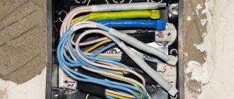
Electrical cables or wires extend from branch boxes to lamps, switches and sockets. They consist of a plastic case with a lid; they can be built-in for hidden electrical wiring (in Figures 3 and 4) and overhead for external wiring (in Figures 1 and 2).
Metal distribution boxes
are subject to mandatory grounding and are installed only when laying electrical cables in metal pipes. For example, in wooden houses and buildings in accordance with the rules and requirements.
Branch boxes vary in size and shape.
Large boxes should be used in places where there will be a large number of cables or wires. It is better to take round ones in shape than square or rectangular ones, because you won’t need to level them. And you can use a hole saw to drill a hole in drywall, block, brick, etc.
Before you start installing the box
it is necessary to make grooves and secure cables in them from the installation site to sockets, switches and lamps. Or secure the cables behind the drywall or panels that line the walls or ceiling.
With open wiring
the overhead box is attached to the ceiling or wall with 2 screws or dowels; just route the electrical cables through special seals. It is necessary to cut a hole in the seals slightly smaller than the diameter of the cable. The illustration shows an option with dust seals. There are waterproof options with rubber seals and threaded plugs.
For installation of a built-in box
it is necessary to knock out or drill a recess into which the box must then be pressed flush. It is much easier to place the box in drywall.
Features of installing sockets without branch boxes
From the machine in the distribution board, the wire of the socket group is laid in a common groove with cables of other groups. At branch points, it does not go into distribution boxes; it goes along its own route in a separately laid channel. In the socket boxes, a loop 15 cm long is made. This part of the cable is intended for cutting and connecting to contacts. This is a proven method of laying cables; then there are several methods for cutting the cable and connecting to the contact group of sockets.
Installation of wiring with a broken line
To connect the wires to the terminals, the loop is cut in the middle, the outer sheath is removed from the cable by 10 - 15 cm, the ends of all wires are stripped 1-1.5 cm from the insulation. The bare ends are attached to the contacts in accordance with the purpose of the colors.
- Blue wire - to the neutral contact;
- Red brown or black for phase contact;
- Yellow - green to the ground terminal.
Each contact clamps two wires coming from the control panel and going to the next socket.
Everything would be fine if it weren’t for the contradictions with clause 1.7.144 of the PUE (Electrical Installation Rules). The grounding wire, designated PE, must be attached to a separate terminal from each consumer (socket with the household appliance turned on). The yellow-green conductor must be solid along its entire length, from the distribution board to the outlet.
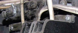
Permanent connections in distribution boxes in the form of welding, soldering, or crimping with special sleeves are allowed. In our case, there are no separation boxes, so this method in relation to the PE wire does not meet the requirements of the guidelines for the installation of electrical wiring. Some electricians neglect this, which is a big mistake. Sections of grounding wire connected between sockets may lose reliable contact. This is facilitated by prolonged load with high currents, an iron or electric heater, hair dryer and other household appliances. When heated, the metal elements on the contacts expand; after disconnecting the load, they cool down, over time this leads to a weakening of the bolted connection of the contact group. The bolts on the contacts must be tightened periodically, otherwise this may lead to a fire.
In the case of a PE conductor, the danger doubles; it is the most important element in the chain of protection of people; the RCD (touch protection device) eliminates electric shock and instantly turns off the network. If in the circuit on one of the sockets the ground wire does not have reliable contact, this socket and all subsequent ones will be left without protection. There will be a threat of current passing to the housing of household appliances connected to sockets, the protection will not work, touching the metal parts of household appliances will lead to electric shock. Therefore, electricians who use this connection method take great responsibility on their conscience.
This drawback does not mean a denial of this method of connection; it is necessary to fold the bare ends of the yellow-green wires at each socket, add a third piece of 4-5 cm, and twist it. Place a copper sleeve of the appropriate size on the connection and press it. Clean the remaining tip of the third wire and secure it to the grounding terminal of the socket. Insulate the sleeve, the connection will be reliable, non-separable, which meets all requirements.
Features of twisting single-wire wires
Single-core wiring is more difficult to twist than multi-core wiring. There are a number of reasons for this:
The current-carrying core is made of a rigid metal rod. If the cross-section is large enough, then it will not be possible to bend it with your hands. The wire has low ductility
It is susceptible to kinks, so you need to work with it with extreme caution. When stripping insulation, the knife blade must be held at an angle of less than 30° to the axis of the wire. Otherwise, the tip will cut into the current-carrying core and damage it. Strippings are carried out no shorter than 50 mm
This is the only way to ensure a good connection. It is advisable to check the finished twist under load. During operation, it should not heat up more than a solid wire without a connection.
Tags: machine, beat, sconce, view, harm, choice, switch, house, , clamp, grounding, replacement, isolate, insulation, cable, how, design, circuit, , installation, voltage, neutral, crimping, soldering iron, connection , potential, rule, check, wire, project, laying, start, , work, size, repair, socket, row, garden, light, lamp, network, twist, connection, connection wire, ten, type, current, , shield, electrical panel, effect