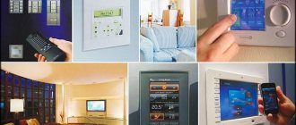
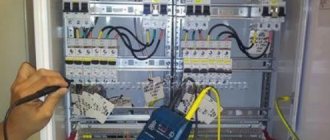
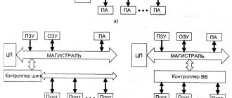
The development of automation tools has led to the creation of complex systems that improve the quality of human life. Many well-known manufacturers of electronics and software environments offer ready-made standard solutions for various objects.
Even an inexperienced user can develop independent projects and assemble a “smart home” using Arduino to suit their needs. The main thing is to understand the basics and not be afraid to experiment.
In this article we will look at the principle of creating and the main functions of an automated home based on Arduino devices. We will also consider the types of boards used and the main modules of the system.
Creating systems on the Arduino platform
Arduino is a platform for developing electronic devices with automatic, semi-automatic or manual control. It is made according to the principle of a designer with clearly defined rules of interaction between elements. The system is open, which allows third-party manufacturers to participate in its development.
A classic “smart home” consists of automated units that perform the following functions:
- collect the necessary information through sensors;
- analyze data and make decisions using a programmable microprocessor;
- implement the decisions made by issuing commands to various devices.
The Arduino platform is good precisely because it is not locked into a specific manufacturer, but allows the consumer to choose the components that suit him. Their selection is huge, so you can realize almost any idea.
We recommend checking out the best smart devices for your home.
To learn how to work with Arduino, you can purchase a Starter Kit on the manufacturer’s website. Knowledge of technical English is required, since the documentation is not Russified
In addition to the variety of connected devices, the programming environment implemented in C++ adds variety. The user can not only use the created libraries, but also program the reaction of system components to emerging events.
Wireless doorbells
In private homes, there may be a significant distance between the entrance gate and the living space, and in order to avoid running wires from the button to the signaling device, wireless bells are used. In such devices, the signal from the pressed button is transmitted to the sound device via radio waves. Wireless calls are very easy to use, and their installation does not require laying cables and is quite simple. The range can be from 30 to 100 meters, so when choosing a call you need to take into account the distance from the gate or front door to the living space. Each call uses its own radio frequency, so even if your neighbors have the same device, they won't affect each other.
Doorbells can be powered by mains or batteries. Of course, in an apartment or private house there is no point in using a device with an autonomous power source, but in a country house or in places where there is no electricity (for example, a bungalow or a hunting lodge in the forest) it will be indispensable. When buying a battery-powered bell, you need to take into account that it may not work well at low temperatures.
Most calls do not have an attractive design and are a simple plastic box. Such devices are designed to be installed in a place invisible to the eye. However, if you plan to place the bell in plain sight, you need to think about its appearance. Today you can purchase bells made in the form of various decorative elements that will fit well into your living room or hallway. Such products do not have to be hidden, but they will become part of the interior of the house.
Main board elements
The main element of a “smart home” is one or more central (mother) boards. They are responsible for the interaction of all elements. Only after identifying the tasks that need to be solved can you begin to select the main node of the system.
The motherboard combines the following elements:
- Microcontroller (processor). Its main purpose is to output and measure voltage in the ports in the range of 0-5 or 0-3.3 V, store data and perform calculations.
- Programmer (not all boards have it). Using this device, a program is written into the microcontroller’s memory according to which the “smart home” will work. It is connected to a computer, tablet, smartphone or other device using a USB interface.
- Voltage regulator. A 5 volt device is required to power the entire system.
Several board models are produced under the Arduino brand. They differ from each other in form factor (size), number of ports and memory capacity. It is based on these indicators that you need to choose a suitable device.
It is better to purchase Arduino boards and shields for them from the manufacturer, as they are of better quality than compatible devices produced in China
There are two types of ports:
- digital , which are marked on the board with the letters “d” ;
- analog , which are marked with the letter “a” .
Thanks to them, the microcontroller communicates with connected devices. Any port can work both to receive a signal and to send it out. Digital ports marked “pwm” are intended for input and output of a PWM (pulse width modulation) signal.
Therefore, before purchasing a board, it is necessary to at least approximately estimate the level of its load on various devices. This will allow you to determine the required number of ports of all types.
It should be understood that the smart home system does not necessarily have to be connected to a control unit based on a single motherboard. Functions such as, for example, turning on artificial lighting in the local area depending on the time of day and maintaining a water reserve in the storage tank are independent of each other.
From the standpoint of ensuring the reliability of the electronic system, it is better to separate unrelated tasks into different blocks, which the Arduino concept makes it easy to implement. If you combine many devices in one place, then the microprocessor may overheat, conflict of software libraries and difficulties in finding and eliminating software and hardware faults.
Connecting many different types of devices to one board is usually used in robotics, where compactness is important. For a “smart home” it is better to use its own base for each task
Each microprocessor is equipped with three types of memory:
- Flash Memory. Main memory where system management program code is stored. A small part of it (3-12%) is occupied by a built-in bootloader program.
- SRAM. RAM, where temporary data necessary for running the program is stored. It features high operating speed.
- EEPROM Slower memory where data can also be stored.
The main difference between types of memory for data storage is that when the power is turned off, the information that is recorded in SRAM is lost, but remains in EEPROM. But the non-volatile type also has a drawback - a limited number of write cycles. This is something to keep in mind when creating your own applications.
Unlike the use of Arduino in robotics, most smart home tasks do not require a lot of memory either for programs or for storing information.
Simple Arduino Projects
Let's start our review with the traditionally simplest, but very important projects, which include a minimum number of elements: LEDs, resistors and, of course, an Arduino board. All examples are designed for use with Arduino Uno, but with minimal modifications they will work on any board: from Nano and Mega to Pro, Leonardo and even LilyPad.
Project with a flashing LED - beacon
Without exception, all textbooks and guides for beginners on Arduino start with an example of LED blinking. There are two reasons for this: such projects require minimal programming and they can be launched even without assembling an electronic circuit - really, and there is an LED on any Arduino board. Therefore, we will not be an exception - let's start with the beacon.
We will need:
- Arduino Uno, Nano or Mega board with a built-in LED connected to pin 13.
- That's all.
What should happen in the end:
The LED flashes - turns on and off at regular intervals (default - 1 second). The speed of switching on and off can be adjusted.
Project diagram
The project diagram is quite simple: we only need an Arduino controller with a built-in LED connected to pin 13. It is with this LED that we will blink. Any popular boards will do: Uno, Nano, Mega and others.
We connect the Arduino to the computer, make sure that the board comes to life and flashes the boot lights. In many boards, the “blinking” sketch is already written into the microcontroller, so the LED can start blinking immediately after switching on.
With this simple beacon project, you can quickly check the functionality of the board: connect it to the computer, upload a sketch, and by the blinking of the LED it will immediately become clear whether the board is working or not.
Programming in the Arduino project
If your board does not have a loaded beacon sketch, it doesn’t matter. You can easily download a ready-made example available in the Arduino programming environment.
Open the Arduino IDE program and make sure the correct port is selected.
Checking the Arduino port - select the port with the maximum number
Then we open the ready-made Blink sketch - it is in the list of built-in examples. Open the File menu, find the sub-item with examples, then Basics and select the Blink file.
Opening the Blink example in Arduino IDE
The open window will display the source code of the program (sketch), which you will need to load into the controller. To do this, simply click on the button with the arrow.
Sketch compile and upload buttons Information in Arduino IDE – Upload complete
We wait a little (you can track the download process below) - that’s all. The board will again blink with several LEDs, and then one of the LEDs will begin its measured cycle of on and off. Congratulations on your first uploaded project!
Beacon project with LED and breadboard
In this project we will create a blinking LED - we will connect it using wires, a resistor and a breadboard to an Arduino. The sketch itself and the operating logic will remain the same - the LED turns on and off.
A graphical representation of the connection diagram is available in the following figure:
Other LED project ideas:
- Flasher (we flash two LEDs of different colors)
- Traffic light
- Light music
- Sleepy beacon
- Beacon - alarm
- Morse code
A detailed description of the connection diagram and logic of the program can be found in a separate article dedicated to projects with LEDs.
Types of boards for assembling a smart home
Let's look at the main types of boards that are most often used when assembling smart home systems.
View #1 - Arduino Uno and its derivatives
The most commonly used boards in smart home systems are Arduino Uno and Arduino Nano. They have sufficient functionality to solve typical problems.
Having full-length boards powered from 7-12 Volts provides many advantages. First of all, this is the possibility of long-term autonomous operation from standard batteries or rechargeable batteries
Main parameters of Arduino Uno Rev3:
- processor: ATMega328P (8 bit, 16 MHz);
- number of digital ports: 14;
- of which with PWM function: 6;
- number of analog ports: 6;
- flash memory: 32 KB;
- SRAM: 2 KB;
- EEPROM: 1 KB.
Not long ago, a modification was released - Uno Wi-Fi, which contains an integrated ESP8266 module that allows you to exchange information with other devices using the 802.11 b/g/n standard.
The difference between the Arduino Nano and its larger counterpart is that it does not have its own 12 V power socket. This is done to achieve a smaller device size, which allows it to be easily hidden in a small space. Also for these purposes, the standard USB connection is replaced by a chip with a mini-USB cable. Arduino Nano has 2 more analog ports compared to Uno.
There is another modification of the Uno board - Arduino Mini. It is even smaller than Nano, and much more difficult to work with. Firstly, the lack of a USB port creates a problem with the firmware, since you will have to use a USB-Serial Converter for this. Secondly, this board is more picky when it comes to power supply - it is necessary to provide an input voltage range of 7-9 V.
For the reasons described above, the Arduino Mini board is rarely used for smart home operation. It is usually used either in robotics or in the implementation of ready-made projects.
View #2 - Arduino Leonardo and Micro
The Arduino Leonardo board is similar to the Uno, but a little more powerful. Another interesting feature of this model is that it is identified as a keyboard, mouse or joystick when connected to a computer. Therefore, it is often used to create original gaming devices and simulators.
Table of sizes and dimensions of Uno, Leonardo and their miniature analogues. The developers did not follow the logic in the names - “nano” should be the smallest
The main parameters of Arduino Leonardo are as follows:
- processor: ATMega32u4 (8 bit, 16 MHz);
- number of digital ports: 20;
- of which with PWM function: 7;
- number of analog ports: 12;
- flash memory: 32 KB;
- SRAM: 2.5 KB;
- EEPROM: 1 KB.
As can be seen from the list of parameters, Leonardo has more ports, which allows this model to be loaded with a larger number of sensors.
Also for Leonardo there is a miniature analogue with absolutely identical characteristics called Micro. It does not have a 12V power supply and instead of a full USB input there is a chip for a mini-USB cable.
The Leonardo modification called Esplora is a purely gaming model and is not suitable for the needs of a “smart home”.
View #3 - Arduino 101, Arduino Zero and Arduino MKR1000
Sometimes the operation of smart home systems implemented on the basis of Arduino requires a lot of computing power, which 8-bit microcontrollers are not able to provide. Tasks such as voice or image recognition require a fast processor and a significant amount of RAM for such devices.
To solve such specific problems, powerful boards that operate according to the Arduino concept are used. The number of ports they have is approximately the same as that of Uno or Leonardo boards.
Arduino 101 has the same dimensions as Uno or Leonardo, but weighs almost twice as much. The reason for this is the presence of two USB inputs and additional chips
One of the easiest to use yet powerful boards, Arduino 101 has the following characteristics:
- processor: Intel Curie (32 bit, 32 MHz);
- flash memory: 196 KB;
- SRAM: 24 KB;
- EEPROM: no.
Additionally, the board is equipped with BLE functionality (Bluetooth Low Energy) with the ability to easily connect ready-made solutions, such as a heart rate sensor, receiving information about the weather outside the window, sending text messages, etc. A gyroscope and an accelerometer are also integrated into the device, but they are used mainly in robotics.
Another similar board, Arduino Zero, has the following indicators:
- processor: SAM-D21 (32 bit, 48 MHz);
- flash memory: 256 KB;
- SRAM: 32 KB;
- EEPROM: no.
A distinctive feature of this model is the presence of a built-in debugger (EDBG). With its help it is much easier to find errors when programming the board.
When writing voluminous code, even a highly qualified programmer experiences errors. To find them, use a debugger
Arduino MKR1000 is another model suitable for high-power computing. It has a microprocessor and memory similar to the Zero. Its main difference is the presence of an integrated Wi-Fi chip with the 802.11 b/g/n protocol and a crypto chip with support for the SHA-256 algorithm to protect transmitted data.
View #4 - Mega family models
Sometimes it is necessary to use a large number of sensors and control a significant number of devices. For example, this is necessary for the automatic operation of distributed air conditioning systems, which maintain a certain temperature for individual zones.
For each local area, it is necessary to monitor the readings of two temperature sensors (the second is used as a control one) and, in accordance with the algorithm, adjust the position of the damper, which determines the volume of warm air entering.
If there are more than 10 such zones in a cottage, then more than 30 ports are needed to control the entire system. Of course, you can use several Uno-type boards under the common control of one of them, but this creates additional switching difficulties. In this case, it is advisable to use models of the Mega family.
The size of the Mega family boards (101.5 x 53.4 cm) is larger than that of the previously reviewed models. This is a technical necessity - otherwise such a number of ports cannot be placed
The Arduino Mega board is based on a fairly simple 8-bit 16 MHz microprocessor aTMega1280.
It has a large amount of memory:
- flash memory: 128 KB;
- SRAM: 8 KB;
- EEPROM: 4 KB.
But its main advantage is the presence of many ports:
- number of digital ports: 54;
- of which with PWM function: 15;
- number of analog ports: 16.
This board has two modern varieties:
- Mega 2560 is based on the aTMega2560 microprocessor, characterized by a large amount of flash memory - 256 KB;
- Mega ADK, in addition to the aTMega2560 microprocessor, is equipped with a USB interface with the ability to connect to devices based on the Android operating system.
The Arduino Mega ADK model has one feature. When connecting a phone to a USB input, the following situation is possible: if the phone needs charging, it will begin to “pull” it from the board. Therefore, there is an additional requirement for the electricity source - it must provide a current of 1.5 amperes. When powering via batteries, this condition must be taken into account.
You can make autonomous power supply for Arduino using connected batteries or accumulators. By combining serial and parallel connections you can achieve the desired voltage and long operating time
Due is another model from Arduino that combines the power of a microprocessor with a large number of ports.
Its characteristics are as follows:
- processor: Atmel SAM3X8E (32 bit, 84 MHz);
- number of digital ports: 54;
- of which with PWM function: 12;
- number of analog ports: 14;
- flash memory: 512 KB;
- SRAM: 96 KB;
- EEPROM: no.
The analog contacts of this board can work both in the usual 10-bit resolution for Arduino, which is made for compatibility with previous models, and in 12-bit, which allows you to receive a more accurate signal.
Let's write a simple program and upload it to Arduino
The Arduino IDE uses a simplified C++ programming language that is easy for beginner programmers to understand. For example, let's write a program that will turn on an LED with an interval of 1.5 seconds. To do this, launch the IDE and paste the code below:
In the line “int ledPin = 13” we declare the digital variable ledPin and whistle the value 13 to it. In the “setup” function we set port 13 as outgoing. In the “loop” cycle, using the “digitalWrite” operator, we turn on and off the LED. And using the “delay” operator we make a delay of 1.5 seconds twice. As a result, the endless “loop” will turn off and turn on our LED for 1.5 seconds.
The connection diagram using a set of Arduino Uno board and LED for our program is shown in the figure below.
To download the program to the Arduino Uno, you need to connect the board to your computer using a USB cable. If the connection is successful, the “ON” LED will light up and the “L” LED will blink.
After that, in the “Sketch” menu, click the upload button.
After compiling and loading the program, the LED on the device will begin to blink.
Features of module interaction via ports
All modules that will be connected to the board have at least three outputs. Two of them are power wires, i.e. “ground”, as well as a voltage of 5 or 3.3 V. The third wire is logical. It transmits data to the port. To connect the modules, special wires grouped in groups of 3 are used, which are sometimes called jumpers.
Since Arduino models usually have only 1 voltage port and 1-2 ground ports, in order to connect several devices you will need to either solder wires or use breadboards.
You can connect not only the power and ports of the Arduino board to the breadboard, but also other elements, such as resistance, registers, etc.
Soldering is more reliable and is used in devices that are subject to physical impact, such as control boards for robots and quadcopters. For a smart home, it is better to use development boards, as it is easier both when installing and when removing the module.
Some models (for example, Arduino Zero and MKR1000) have an operating voltage of 3.3 V, so if a higher value is applied to the ports, the board may be damaged. All information on power supply is available in the technical documentation for the device.
Executable part
For the executable part, “family” relay modules on 4 lines are taken. You can find similar ones on AliExpress at a price of about 200 rubles. The main thing when choosing is a trigger voltage of 5 V, with switched AC up to 250 V/10 A. These boards are quite easy to connect to Arduino and do not require galvanic isolation. A module combining several relays has separate inputs that activate each of the triggers. In addition, +5 V and GND from Arduino are supplied to it, through a filter that reduces the chance of a drop in the overall system voltage.
The power equipment will be connected through high load repeating relays. Despite the statements of module manufacturers, it is not worth taking risks with powerful consumers on the final board connected directly to Arduino.
LEDs Led1-4 in the diagram are more related to the interface part and show the current operating mode: 1 - security is disabled, 3 - activated, 2 - people at home, 4 - energy saving. The street lamp and in the pantry are ordinary household lamps for 220 V.
Add-on boards (shields)
To increase the capabilities of motherboards, Shields are used - additional devices that expand the functionality. They are manufactured for a specific form factor, which distinguishes them from modules that are connected to ports. Shields are more expensive than modules, but working with them is easier. They are also equipped with ready-made libraries with code, which speeds up the development of your own control programs for a smart home.
Proto and Sensor shields
These two standard shields do not add any special functionality. They are used for more compact and convenient connection of a large number of modules.
Proto Shield is an almost complete copy of the original in terms of ports, and you can glue a development board in the middle of the module. This makes it easier to assemble the structure. Such add-ons exist for all full-length Arduino boards.
Proto Shield is placed on top of the motherboard. This slightly increases the height of the structure, but saves a lot of space in the plane
But if there are a lot of devices (more than 10), then it is better to use more expensive Sensor Shield switching boards.
They do not have a bradboard, but all port pins are individually supplied with power and ground. This allows you to avoid getting tangled in wires and jumpers.
The surface area of the motherboard and sensor boards is the same, but there are no chips, capacitors and other elements on the shield. This frees up a lot of space for full connections.
This board also has connectors for easily connecting several modules: Bluetoots, SD cards, RS232 (COM-port), radio and ultrasound.
Connecting auxiliary functionality
Shields with functionality integrated into them are designed to solve complex but typical problems. If you need to implement original ideas, it is better to choose a suitable module.
Motor Shield. It is designed to control the speed and rotation of low-power motors. The original model is equipped with one L298 chip and can drive two DC motors or one servo at the same time. There is also a compatible third-party part that has two L293D chips with the ability to control twice as many drives.
Relay Shield. A frequently used module in smart home systems. A board with four electromechanical relays, each of which allows the passage of current with a force of up to 5A. This is enough to automatically turn on and off kilowatt devices or lighting lines designed for 220 V alternating current.
LCD Shield. Allows you to display information on a built-in screen, which can be upgraded to a TFT device. This extension is often used to create weather stations with temperature readings in various living spaces, outbuildings, garages, as well as temperature, humidity and wind speed outside.
The LCD Shield has built-in buttons that allow you to program information scrolling and select actions to send commands to the microprocessor
Data Logging Shield. The main task of the module is to record data from sensors onto a full-format SD card up to 32 Gb with support for the FAT32 file system. To record to a micro SD card you need to purchase an adapter. This shield can be used as an information storage, for example, when recording data from a DVR. Manufactured by the American company Adafruit Industries.
SD Card Shield. A simpler and cheaper version of the previous module. Many manufacturers produce such extensions.
Ethernet Shield. Official module for connecting Arduino to the Internet without a computer. There is a slot for a micro SD card, which allows you to record and send data via the World Wide Web.
Wi-Fi Shield. Allows wireless exchange of information with support for encryption mode. Serves to connect to the Internet and devices that can be controlled via Wi-Fi.
GPRS Shield. This module is usually used to communicate between a smart home and its owner via mobile phone via SMS messages.
Table for connecting circuit elements to Arduino UNO R3
Let's summarize all the connections between Arduino and external devices into a single table, which will help in assembling the finished circuit.
| Where | Arduino UNO R3 pin | Device pin/contact |
| Module for 4 relays D0 general lighting, D1 heating, D2 light in the pantry, D3 outdoors. | D0 | D0 |
| D1 | D1 | |
| D2 | D2 | |
| D3 | D3 | |
| Arming/disarming button | D4 | |
| Economy mode/people at home key | D5 | |
| D6 | ||
| Communication with the modem | D7 | RX |
| D8 | TX | |
| LED security disabled (red) | D9 | |
| Security activated (green) | D10 | |
| Owners of the house (kr) | D11 | |
| Economy mode (green) | D12 | |
| Turning on the modem | D13 | D9 |
| Reed switch storage room | A1 | |
| Reed switch door/gate | A2 | |
| Thermometer | A3 | |
| Determining the presence of a 220 V network | A4 |
The planned system did not completely occupy all the pins of the microcontroller. There is still room to add an analog sensor and one control line. An option is to use free contacts for the smoke sensor and alarm. If you plan to expand the design further, you will have to take the Arduino Mega microcontroller. It has more I/O ports and memory, with full software compatibility.
Smart home modules
Connecting modules from third-party manufacturers and the ability to work with them using the built-in programming language is the main advantage of the open Arduino system compared to “branded” smart home solutions. The main thing is that the modules have a description of the received or transmitted signals.
Ways to obtain information
Information input can be done through digital or analog ports. It depends on the type of button or sensor that receives the information and transmits it to the board.
For a computer program, a digital signal corresponds to periods with “0” and “1”, and an analog signal determines the range of values in accordance with its dimension
A signal to the microprocessor can be sent by a person who uses two methods for this:
- Pressing a button (key) . The logical wire in this case goes to the digital port, which receives the value “0” if the button is released and “1” if it is pressed.
- Rotating the cap of the rotary potentiometer (resistor) or shifting the slider lever. In this case, the logical wire goes to the analog port. The voltage passes through an analog-to-digital converter, after which the data goes to the microprocessor.
Buttons are used to start an event, for example, turning lights, heating or ventilation on and off. Rotary knobs are used to change the intensity - increase or decrease the brightness of the light, the volume of the sound or the speed of rotation of the fan blades.
A potentiometer is a simple device, so it is very cheap. Its main characteristics are electrical resistance and rotation angle
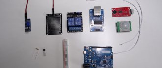
Sensors are used to automatically determine environmental parameters or the origin of an event.
The following types are most in demand for smart home operation:
- Sound sensor. Digital versions of this device are used to activate an event using clap or voice. Analog models allow you to recognize and process sound.
- Light sensor. These devices can operate in both visible and infrared ranges. The latter can be used as a fire warning system.
- Temperature sensor. Different models are used for indoors and outdoors, since the external ones are better protected from moisture. There are also remote devices on the wire.
- Air humidity sensor. The DHT11 model is suitable for indoors, and the more expensive DHT22 for outdoors. Both devices can also provide temperature readings. Connect to a digital port.
- Air pressure sensor. Analog barometers from Bosh have proven themselves to work well with Arduino boards: bmp180, bmp280. They also measure temperature. The bme280 model can be called a weather station, since it also provides an additional humidity value.
- Motion and presence sensors. They are used for security purposes or to automatically turn on lights.
- Rain sensor. Reacts to water entering its surface. It can also be used to trigger an alarm for leaks in the plumbing or heating circuit.
- Current sensor. They are used to detect non-working electrical appliances (burnt out lamps) or to analyze voltage to prevent overload.
- Gas leak sensor. Used to detect and respond to increased concentrations of propane.
- Carbon dioxide sensor. It is used to determine the concentration of carbon dioxide in living rooms and in special rooms, such as wine cellars, where fermentation occurs.
There are many more different sensors for specific tasks, for example, for measuring weight, water flow speed, distance, soil moisture, etc.
Some sensors, such as the anemometer, which measures wind speed and direction, are complex electromechanical instruments
Many sensors and sensors can be made independently using simpler components. It will cost less. But, unlike the use of serial devices, you will have to spend time on calibration.
Control of devices and systems
In addition to collecting and analyzing information, a “smart home” must respond to emerging events. The presence of advanced electronics on modern household appliances allows you to access them directly using Wi-Fi, GPRS or EtherNet. Typically, Arduino systems implement switching between a microprocessor and high-tech devices via Wi-Fi.
In order to use Arduino to turn on the air conditioner when the temperature in the house is high, block the TV and Internet at night in the children's room, or start the heating boiler when the owners arrive, you need to perform three steps:
- Install the Wi-Fi module on the motherboard.
- Find unoccupied frequency channels to avoid system conflict.
- Understand device commands and program actions (or use ready-made libraries).
In addition to “communicating” with computerized devices, tasks often arise that involve performing some mechanical actions. For example, you can connect a servo drive or a small gearbox to the board, which will be powered from it.
The servo drive consists of a motor and several gearboxes. Therefore, despite the low current (5 V), it can develop decent power, which is enough, for example, to open a window
If it is necessary to connect powerful devices operating from an external power source, two options are used:
- Inclusion in the relay circuit.
- Connecting a power switch and triac.
An electromagnetic or solid-state relay connected to an electrical circuit closes and opens one of the wires according to a command received from the microprocessor. Their main characteristic is the maximum permissible current (for example, 40 A) that can pass through this device.
As for connecting a power switch (mosfet) for direct current and a triac for alternating current, they have a lower permissible current (5-15 A), but can smoothly increase the load. It is for this purpose that PWM ports are provided on the boards. This property is used when regulating lighting brightness, fan speed, etc.
Using relays and power switches, you can fully automate all electrical circuits at home and start the generator in the absence of current. Therefore, on the basis of Arduino, it is possible to implement autonomous provision of an apartment or building, including all particularly important functions - heating, water supply, drainage, ventilation and security system.
Do you want your home to become smarter, but with programming for “you”? In this case, we recommend looking at ready-made solutions from Xiaomi and Apple, which are easy to install and configure even for a beginner. And you can set commands and control their implementation even from your smartphone.
Read more about smart home from Xiaomi and Apple in the following articles:
- Xiaomi smart home: design features, overview of main components and working elements
- Apple smart home: subtleties of organizing home control systems from the Apple company
Power reserve
There are many ways to provide backup power. Since one of the requirements for a do-it-yourself smart home project was efficiency, conventional batteries connected in series to produce 5 V will be used as a reserve. A description of the interface for recharging them is beyond the scope of the article and the owners will have to ensure the availability of stored energy themselves. Periodic recharging with a “frog”, once every few months, will not be a problem for the end user.
The operating principle is simple. When the 220 V network is turned off, the normally open relay K1 connects the Arduino and the modem with +5 battery power. At the same time, the HIGH state is set at input A4 of the microcontroller. The latter is analog, which means you can control the battery charge through it by empirically calculating at what minimum readings the logical components turn off. Informing a person about the discharge is done by sending SMS.
Conclusions and useful video on the topic
An example of a self-assembled entry-level workpiece for a “smart home”:
The openness of the Arduino platform allows the use of components from various manufacturers. This makes it easy to design a “smart home” to suit the user’s needs. Therefore, if you have at least minor knowledge in the field of programming and connecting electronic devices, this system is worth paying attention to .
Are you familiar with the Arduino platform in practice and want to share your experience with newcomers to this matter? Maybe you would like to supplement the above material with useful recommendations or comments? Write your comments under this publication.
If you have any questions about designing an automated home system based on Arduino, ask them to our experts and other site visitors in the block below.
Possible functionality and setting system requirements
Before moving on to the design part, you first need to describe to yourself what is required from a particular system.
The complex will be installed in a small house (dacha), located quite far from housing and communications. The heating in it is based on electric heating elements, which also imposes its own limitations. The house is rarely visited in the cold part of the year, but the heating should not freeze out. Saving in the absence of people is mandatory. The latter also applies to lighting fixtures that are accidentally left on - they should turn off on their own.
Another important factor that requires constant monitoring is home security. In any way, a person must find out about strangers entering the house.
Since the arrival takes place in the dark, any owner wants the moment of opening the doors and moving around the yard to be illuminated. What to consider when designing a system. So, in total:
- Identification of the passage through the gate of the area, to illuminate the path if necessary.
- Determining the opening of the front door to the house.
- Heating system control. In the absence of the owners, keep the temperature at least 5 ℃ so that the water does not freeze. Based on the received command, warm up the room remotely to +20 degrees.
- Inform the owner about power outages so that the refrigerator does not defrost.
- Turning on the light in the closet when someone opened the door.
- You can get all of the above at a minimal cost.
- Turn off all electrics and put the house into energy saving mode. The refrigerator continues to work.
There are many smart home projects using Arduino, but they are too expensive for the capabilities described. It’s easier to assemble a similar system yourself.
Control
Using this software, you can not only receive information from the system, but also carry out control - for example, activate and deactivate the alarm. If the option is active, then when the motion sensor is activated, the program will receive the corresponding information. Note that the program polls Arduino to activate the motion sensor at intervals of once every 60 seconds.
The next stage of connection is setting up the browser program for use with a smart home. In the address bar you need to enter a certain sequence, which will be the IP address of your computer. After performing this action, the user will have access to the ability to receive information from the “smart home” and the ability to control it.
After this, you can proceed to working with the router. A port should be opened on it.
This can be done using the following algorithm:
- open settings;
- register the address of the Arduino microcontroller;
- open port eightieth.
Now you should set up an account on the Noip portal. com. Although this step is optional, it is necessary if the address needs to be given a domain type name. You need to go through the registration procedure on the portal www. noip. com, then go to the Add host category and specify IP systems. After completing this procedure, you will be able to access not only via IP, but also via domain. At this point, the formation of the project is completed and the system can be checked to determine its operability.
Advantages of the 2560 microcontroller
Arduino is a popular platform for implementing various projects, suitable for engineers who do not want to program “empty” microcontrollers and, in principle, want to reduce communication with the software environment to a minimum.
But even in the basic configuration it has its pitfalls, which it is better to know about in advance.
Gradually setting yourself more complex tasks and engaging in new developments on this MK, you will eventually encounter two main problems with standard boards:
- Suboptimal sizes, not suitable for convenient placement in many cases.
- Lack of number of pins for data input/output.
Problem #1
It is extremely easy to minimize the space you take up - just use special types of MK, be it nano or mini. There are some features here with a lack of memory, for example, on the Attiny85, but for simple functionality this is not so significant.
Of course, for more complex tasks you can buy special modules with additional memory for instructions, but this completely eliminates all the advantages of the nano, because the reduced size will be compensated by an additional slot for the chip and a occupied pin. This problem does not apply to all boards, and the same nano is capable of completely copying the functionality of the uno.
Problem #2
Less pleasant, but there are several ways to solve it:
As we see, both ways out of the situation involve “crutches”, and they cannot be called elegant. But this is far from the only problem. They either work partially or neutralize the advantages of the system, which is absolutely unacceptable for any complex projects.
Fortunately, there is a third approach that is being used more and more often - Arduino Mega 2560, projects on which no longer suffer from the abundance of these “crutches”. There is also an analogue of this board that supports USB hosts, but let's first look at the main MK.
The first thing that catches your eye when you meet the 2560 is its appearance, because it is 1.8 times longer than the UNO, which is a necessary evil in order to accommodate as many as 54 ports on it.
Moreover, 15 of them can be used as sources of PWM signals to regulate current power or other system parameters. Regulation is carried out using pulse-width modulation, and additional 16 input ports can process digital signals and be used as the same digital outputs. As a result, we get a thinner, longer and more functional board.
For communication with several types of devices, 4 UART interfaces are installed, on pins 0, 1, 14, 19. Moreover, one of them is directed to USB using the ATmega8U2 microcontroller, used as a replacement for the usual USB-TTL, which was used everywhere in older boards.
But, what’s more important, the firmware is located in a public repository and, accordingly, is available for downloading and modification to anyone. For communication with displays, there are SPI and I2C technologies, which you can also use in your project.
