Definition of ShchR
Electrical distribution board - complete device. It is used for single- or three-phase power supply of objects with Uc<1000 V. The switchboards perform protective functions (against short circuits during overload), switching on (switching off) individual lines in complex circuits. ShchR distributes electricity for the functioning of technical consumer equipment across floors, rooms, sectors, and is installed in buildings of any purpose, apartments. Also used in various power and lighting installations for connection to the electrical supply system. They are classified depending on the specific application.
Basic standards defining conventional images on electrical wiring diagrams
Everything related to electrical engineering, electrical engineering, etc. is standardized by regulations of the International Electrotechnical Commission, IEC (International Electronic Commission, IEC).
The symbols on the diagrams are regulated by the IEC standard IEC 60027.
In the Russian Federation, symbols on diagrams are standardized by GOST 21.614-88 “Conventional graphic images of electrical equipment and wiring on plans”, from the section “Design documentation system for construction”. This standard came into force on 07/01/88 and completely replaced the now defunct GOST 2.754-72.
Also in the GOST section “Unified system of design documentation”, in GOST 2.721-74 “Conventional graphic symbols in diagrams. Designations for general use”, symbols for all products, including electrical ones, have been standardized.
The differences between these two standards are as follows. If you have to read a diagram, for example, of an input distribution device or an electrical panel diagram, then the symbols in these diagrams correspond to the GOST 2.721-74 standard.
The electrical wiring diagram in an apartment or house will be made according to the symbols of GOST 21.614-88. By the way, only this GOST standardizes the symbols of sockets, switches and other electrical installation equipment.
Types of distribution boards
main switchboard
The main switchboard performs the function of an ASU (distribution device at the input of the power supply line into the building). Transmits electricity to power supply units for other purposes or directly to consumers: equipment, sockets, switches.
ASU
The purpose of the input distribution device is to receive electricity from any source to which the facility is connected (power line, power cable or transformer). The configuration of this type of shields is different, but the main structural elements are the same:
- box (cabinet);
- switch (input machine);
- electricity meter (meter);
- power buses;
- relays, contactors;
- current transformer;
- voltage limiter;
- patch wires.
ASUs are used to organize power supply to industrial facilities, buildings for various purposes (residential, public, administrative), and at substations. Depending on this, the structure of the distribution board differs, but the purpose of the ASU is similar to the main switchboard.
Automatic reserve input
Distribution boards of this group are marked as AVR. They are used when transferring consumers to a spare (backup) source of electricity (battery group, generator) in case of overloads, accidents, or a sharp drop in Uc. The automation of the ATS switchboards controls the parameters of the power supply network and gives a switching command in cases of detected failure.
Group distribution boards
An intermediate link between the main switchboard and end consumers or another panel (SCHSN). Used for protection and power supply of individual groups of units and devices. Using switching equipment, you can turn on (turn off) certain lines without leaving the entire facility without power.
ShchS
Designation of the power (or communication) distribution board. Used in circuits with separation of consumers by power. The “stuffing” is switching equipment, control devices, and devices for collecting data on the operation of the equipment.
SHU (SHCHU)
Control distribution boards (automation). They are installed at facilities with automated control systems to connect various systems: air conditioning, ventilation, lighting, PIC, access control systems and others.
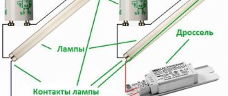
SCHO
Lighting (heating) distribution boards. They are equipped with the equipment necessary to control the operation of the equipment and monitor its functioning.
SHE
The floor distribution board is installed on landings (in niches, on walls) in each entrance of an apartment building. Equipped with electric meters and circuit protection elements. Through it, power is supplied from the ASU (main switchboard) to each apartment on the floor.
ShchK
A distribution board installed in an apartment makes it possible to quickly manage the power supply to various electricity consumers without going out to the entrance. Powerful household appliances (hobs, dishwashers, wall-mounted boilers) are connected to the network via separate lines. This also applies to sockets and lighting equipment. As a rule, protective devices (AV, RCD, differential circuit breakers) are installed in the control panel. Purpose: distribution of electricity from the distribution board along the circuits of the residential power supply circuit.
ShCHSN
Distribution board for own needs. A device for direct (individual) use, used to connect one powerful consumer to the power line. ShchSN is equipped with machine tools, complex units of technological lines, and electrical installations.
Distribution metering board
Boxes of this category are distinguished by tight cable entries and the presence of “ears” for sealing the cabinet, preventing unauthorized access to instrumentation.
SHPT
Distribution boards of this group are mounted in DC power circuits. The sources are battery groups, rectifier units, chargers, which are often used at sites as a backup: emergency lighting and the like.
Portable distribution board
Mobile boxes for temporary power supply to consumers. A special feature is increased protection from external factors, ease of replacement of a damaged circuit element.
Shield marking - mandatory requirements
Applying markings - special designations created according to certain rules regulated by the requirements of GOST, TU and PUE. Marking the electrical panel is a mandatory operation during the production and assembly of products in St. Petersburg and Leningrad Region. This designation method is useful information for the user, helping to quickly identify consumer groups (lighting, sockets, household appliances). If it is necessary to turn on or turn off the consumer, you can easily find the required machine.
Marking the panel is necessary during the operation and maintenance of the electrical system, usually with the involvement of various repair and maintenance personnel.
ShchR classification
Design Feature
- External boxes. Distribution boards of this class are often used to connect cables laid in an open way. They are characterized by ease of installation and ease of access. As a rule, on walls, supports, structural elements of buildings. To protect the layout from moisture, they are equipped with additional insulation.
- Indoor installation boxes. The built-in distribution board is used in private houses, administrative and other buildings where the electrical wiring is done in a hidden way and the cable is not thick. Otherwise, it is difficult to pull the harness through the mounting hole in the box wall. Internal distribution boards are installed in niches, prepared openings in partitions, walls, if the number of connected lines is 2 times less than the number of modules in the cabinet. Fits well into the interior - only the box lid is visible, disguised as the decoration of the room; The ShchR body is recessed and cannot be seen.
Mounting method
- Mounted distribution board. The most common type of ShchR, used in electrical networks of any type of installation (hidden, open). For mounting on the base there are “ears” or holes in the rear wall of the case. That’s why the distribution board is also called overhead.
- Floor distribution board. The box is large in size, installed on a prepared site or attached directly to the floor if the coating provides strength and stability. Scope of application: industrial, administrative facilities, construction sites.
Housing material
- Polymer. Plastic distribution boards are cheaper than metal boxes, but are inferior to them in mechanical strength. Otherwise, there are only advantages: they weigh less, do not require additional insulation when operating in damp conditions. A significant advantage is that the installation of a distribution board of this category does not require mandatory grounding of the box. Recommended for installation with a two-wire power supply circuit (control systems, lighting and a number of others). Some manufacturers of metal frames install a dielectric polymer shell inside the box. Such boxes, although conditionally, are classified as plastic.
- Metal. A typical example is a street distribution board. A distinctive feature of this group of products is the high strength of the case. If the layout provides for the presence of powerful switching devices, the plastic will not withstand significant dynamic loads when the releases are triggered. A metal distribution board is needed where the rating of modular equipment exceeds 63 A. You cannot do without such a box when equipping the door with measuring instruments, lighting equipment, and switching devices. The box body is used as GND or common zero.
Switchboard: characteristics
- Number of modules. According to this criterion, SCs are divided into small (2–12), medium (16–24) and large (36, 48, located at several levels).
- Switchboard protection degree. When assessing this characteristic, you need to focus on the devices installed in the box.
IP20 (30) - for installation inside a building, in rooms with normal humidity.
IP44 (IP54) - ShchR are protected from dust and moisture, but direct exposure to liquid on the housing is contraindicated.
IP55 (65) - for installation outside the building, operation in conditions of contact with an aggressive environment.
- Boxing dimensions. Geometry affects the internal layout and ease of installation. When choosing a ShchR, the useful internal volume, the number of inputs, the dimensions and number of DIN rails, and how many modules will fit on one are assessed.
Methods for marking electrical panels
There are various ways to mark the panel, wires, and components:
- electrical panel housing - the presence of a nameplate indicating the manufacturer’s coordinates, electrical characteristics (voltage, current, frequency and others) or mechanical parameters (weight, dimensions, degree of protection), warning notices;
- components of electrical panels - icons indicating a particular device (kitchen lighting, heating boiler and other consumers);
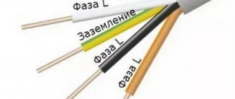
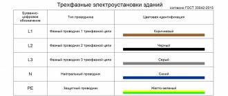
- marking of electrical panel wires – regulated by standards and PUE, individual wires and group circuits are marked. Color and alphanumeric marking methods are used;
- three-phase systems - phase “A” is yellow; “B” is green, “C” is red.
Compliance with the established rules for marking the electrical panel reduces the likelihood of errors. As a result, the likelihood of a short circuit or electric shock is minimized. Therefore, every specialist must understand that marking the shield and component elements of the system facilitates maintenance and protects personnel.
The Vulelectro company offers to mark the electrical panel in accordance with current standards in St. Petersburg and the Leningrad region. To place an order, the client can call or email [email protected]
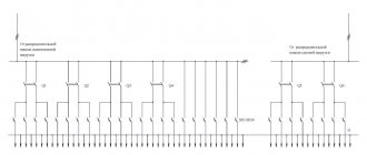
Electrical diagram of the distribution board
It is developed based on the purpose of the ShchR and the specifics of use. The schemes differ in complexity, layout, and number of modules. But the principle of their construction is the same.
- Availability of an input switch (switch, AB).
- Mandatory protection of secondary circuits from overloads and short circuits.
- Eliminating the risk of electric shock to the user (differential circuit breakers, RCDs).
Requirements of governing documents
It is useless to list them in detail - the average user is not able to remember everything stated in the regulatory documentation regarding switchboards. When developing a circuit, choosing a control unit, and installing it, the following recommendations should be taken into account:
- PUE (7th edition, section 4);
- GOST;
- SNiPov;
- SP (set of rules 9.131.30 of 2009);
- RD.
All requirements are advisory in nature, as stated in the letter of the Federal Supervisory Service dated May 27, 2011. Various documents place emphasis on ensuring protection:
- health, human life;
- property of any form of ownership;
- environment, flora, fauna.
Purchasing, assembling a distribution board, installing, connecting - in these matters you cannot do without consulting a professional. When working with electrical devices, amateur activity is unacceptable and very dangerous.
The choice of distribution board is made taking into account many factors: installation method, purpose, layout, the size of the gap between the back wall of the box and the DIN rail, and a number of others. Contact us, we have ShchR of all types and sizes in stock. We will help you understand the assortment, select the optimal version of the product, and offer an electrical distribution board for any assembled circuit.
CS-CS.Net: Laboratory of the Electroshaman
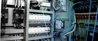
Power three-phase switchboard with automation
Here comes the adventure again! One customer called me here and said: “Can I assemble a shield? Just for me URGENTLY!” I answer him: “Yes, no problem!” And then it turns out: apartment, three-phase input 20 kW, approximately 52 cables, it is necessary to make two non-priority groups, non-switchable lines. And for all this, I bought a Mistral IP65 for 72 modules and there is absolutely NO space around from the word “AT ALL”. And we also bought a bunch of single-module machines.
First of all, the customer tried to ask me to fit into this shield and somehow shrink. The dialogue went something like this:
—Who do you work and what do you do? — Networks, IT. - Yeah, well, just imagine - according to your project, you are asked to save on a 19″ cabinet and instead of a good switch with 48 ports, throw small eight-port ones into the premises. Would you do that? - Of course not! - So I won’t!
And after that we began a feverish search for a solution. As a result, on the opposite wall, to the detriment of part of the dressing room, the customer managed to come up with a small metal box, where they decided to put an EDF panel of 2x5 slats. Well, our main shield has turned into an IPM (power management) shield. I installed NovaTek OM-310 there in order to get two non-priority groups. Non-switchable lines were also made there, as well as a NovaTek REV-302 time relay to control the emergency lights in the apartment. I made protection against emergency voltage based on the RN-106 relay from NovaTek, because Meander had completely rotted away (I once promised to finish it, but I quietly gave up and have been using products from NovaTek for a long time).
From the IPM board, power is supplied to the second power board, where it is already distributed to RCDs and automatic circuit breakers. For a three-phase shield, we used a budget circuit with four-pole RCDs and two-pole circuit breakers. And for non-disconnectable lines, I installed difautomats, because these lines are responsible for different loads and should not influence each other (so that if something happens to one line, all of them are not cut off at once).
Well, and most importantly, this was the first board on which I was able to test my new marking system using the GODEX G500 thermal transfer printer and consumables from WAGO, so most of the photos will be devoted to a description of the marking and how to use it and how it went down on the shield. Well, these two shields were also assembled at a very urgent pace, because they had to be done extremely urgently. I strained myself and finished them at one in the morning (and by the morning at 8-9 am I had already passed them). Because of this, some of the photos in the post are good and bright, while the other part is dark, because they were taken at night and their white balance was off.
So, first I debugged 1Sku so that it would give me the necessary printouts automatically, and then I printed all the necessary characters on the printer, getting a long tape.
Printed labeling for the module
Then at first my hands seemed to reach out to the desire to glue special GraphoPlast pads for marking, and I was dumb for a long time, getting used to the idea that now I can not glue anything, but immediately sculpt printed markers directly onto the machines. In the end, it turned out cool and convenient - you take the machines almost right out of the box and label them!
Labels can be applied straight out of the box
This is what it all looked like while working.
The marking is pasted on the module
Along the way, you need to let in a little bit of anger and curse WAGO a little. Firstly, in a vulgar post I already scolded them for their lack of contact and some lack of interest in their own goods. Secondly, I am very surprised by the price of their consumables and the fact that textile and softer labels (201-811/000-002) cost almost 17-18 thousand per handle.
Thirdly, cheaper labels (item 210-805/000-002) have several features. They are more rigid and I am concerned about how well they will stick to an uneven machine (it consists of two halves, which sometimes give a difference in height). They also don’t stick well to their backing and sometimes peel off from it all at once:
Marking from WAGO - does not adhere to the base very well
Since these are ordinary labels, I think that I will go to https://pos-shop.ru/ and order labels of my own size there for marking the module. At the same time, I will select a material so that they are flexible enough for unevenness, but at the same time have a strong adhesive layer. It’s not difficult to make custom labels like these. It is more difficult to produce special consumables for marking wires, but this is also possible.
And at first it was very inconvenient for me to glue labels on the machines until my hands got used to it. I kept gluing them crookedly. But my hand retrained, and the sticker went very quickly and easily, and I even fell in love with labels like these. I like that they are yellow, because due to the contrast, black on yellow looks very cool and technical. And I love that the label looks like a separate item, lovingly glued onto the shield module.
All elements of the shield are arranged and marked
Here's a close-up of the sticker. It fits well on the module. Surprisingly, it also holds up well and doesn’t fall off on its own. It must be applied with clean hands. Here my print was made with a demo ribbon of the “WAX” type (wax), which is not suitable for printing on plastic, which is why it smears a little on it and wears off when scratched with your hands. RESIN type ribbon (resin) is more durable and should stick to plastic much better. As soon as I finish the test ribbon (there is very little left), I will move on to the correct one. You can also see from the same label that it is not necessary to chase a resolution of 300 dpi - a resolution of 203 dpi is perfectly enough for text readability.
Marking mark on the machine
And these stickers also solved the problem with marking all small things half a module wide. Previously, the GrafoPlast pad stuck out a lot and made it difficult to tighten the screw or insert the wire. Now instead there is a flat sticker that doesn’t interfere with anything! Hooray!
Marking mark on a narrow module (0.5 module)
As a result of all this, we get this beauty:
Marking marks on the modular filling of the shield
On single-module machines (I used some of the customer’s machines) everything also looks beautiful:
Marking marks on the modular filling of the shield
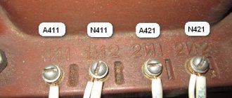
Next, I printed markings for the terminals on the HTP500 (because I also needed to take photos for the blog post):
Printed terminal markings
The markings fell into place perfectly and cool.
Terminal markings installed
Now I’ll tell you more about WAGO’s wire markings. I use tags with item number 211-862. The PuGV wire of 6 squares easily fits into them. I print out the names of the lines that will go to the machines from the cross-module and label them “LQxx”. The designation should be read as “Line Qxx” - line from Qxx.
These markings are convenient and good, and I will order them from WAGO until I figure out if I can make my own similar one. We simply thread the wire through the first hole in the sheet:
Application of markings for WAGO wires
Then I bend the sheet a little and thread the wire through the second hole.
Application of markings for WAGO wires
After this, all that remains is to pull sharply, and the marking is torn out of the sheet and remains on the wire. Convenient as hell!
Marking for WAGO wires
This is what it looks like live on the wires from the cross-module. Of course, the tubes with numbers from GrafoPlast were more convenient when installed more tightly, but this marking also works great. The only thing is that working with it will not be very convenient if we do not have free space near the cross-module. In this case, we will need tweezers to find the desired wire.
Marking for WAGO wires
This is how it’s all packed around the cross-module. Now, if I am not assembling a shield on the AT/U series, then I always try to leave an indentation near the cross-modules for more convenient connection of wires. I step back either with a plastron, or lower the cross-modules a little lower using MBK height-adjustable rails.
Marking for WAGO wires
Well, the terminals in this panel receive power from the first input panel and IPM.
Terminals with printed markings are connected
Here is the shield after assembly. The most interesting thing is that during this time the quality of the screws on IEK cross-modules has improved a little, and they themselves have changed a little and become a little more beautiful.
The shield is fully assembled and marked
So, what happened in this shield? I divided it into three conditional sections: unswitched power, lighting (turned off by a general switch in the entire apartment through a contactor), switched power: sockets, appliances and climate. The fact that each type of food is available is indicated by an indicator light. I used some of the UZOs of type “A” (for sockets and equipment). Since it was necessary to use at least part of the single-pole circuit breakers purchased by the customer, I installed them for lighting and climate control, deciding that if the RCD of light or climate control switched off completely, it would be easier to survive than the permanent disconnection of the RCD of sockets or equipment. Therefore, I have already ordered two-pole circuit breakers for sockets and equipment, which is what should be installed according to my development of a budget three-phase switchboard.
The assembled shield is covered with a plastron
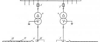
Now let's look at the power management panel (IPM). It was assembled from 22 o'clock to one in the morning, so there was absolutely no time to photograph it, and I will show it in assembled form. Here, too, there are a bunch of solutions that are tailored to a specific customer and object.
Firstly, it turned out that the customer’s input was short and came from below. Therefore, I lowered the rail with the input switch and the emergency voltage protection relay down and even connected the input cable from the bottom of the switch. Then the power goes to the NovaTek OM-310 power limiter, which monitors the network parameters (the customer will connect it through an RS-232/Ethernet converter to the grid) and gives us two groups of non-priority loads. The limiter and its automation are protected by a 6A automatic.
After the power limiter, we receive unswitched power, which goes to our emergency light, to control the apartment lighting and to the full power switch. The idea here is that you can turn off the lights separately, and separately the full power supply to the entire apartment, if necessary.
Input and automation panel IPM
As a non-priority, we have a powerful instantaneous water heater and an evil air conditioner, which requires single-phase (!!) power supply as much as 32A. This is complete CRAZY! Don't do this! If you are already choosing the main external unit of a multi-split, then take it either three-phase with such power or take into account the ratings of the machines. Here it turns out that in the worst case, almost the input circuit breaker will cut off the air conditioner when overloaded (it is also 32A). I had no choice but to push the air conditioner into a non-priority position, because everything had already been selected, purchased and installed. So here's all the hope for the OM-310.
The scheme is designed so that first of all the system tries to turn off the boiler, and then, if this does not help (most of the time the boiler will be turned off), it turns off the air conditioner. If a different sequence of priorities is needed, then in the switchboard it is enough to swap two wires (this is described in the document for the switchboard).
Well, to control the duty lighting, the customer and I installed a NovaTek REV-302 time relay for the sake of experiment (here is my post about them). This is a hellishly sophisticated relay with a voltage sensor and a photosensor that can control two load channels by voltage level, by illumination, or by different clock programs. The clock in it is very accurate straight from the factory: when I first turned it on, I didn’t even have to adjust the time and date - they coincided with the current ones within about a minute! I protected this relay with a 10A circuit breaker and connected its channels to a couple of D4/6.NLP terminals (I gave them to the customer).
Relay NovaTek REV-302 for night lighting control
Actually, now these shields are most likely already standing and working at the customer’s apartment. Well, I’m glad that we were able to help the person and get out of his difficult situation. We were very lucky that we found a place for a second shield and managed to come up with it all and give birth to it. Please understand that projects from dubious designers are not always correct and that a panel for a large apartment will not always occupy 72 modules. If done correctly (in terms of installation, protection, automation), it will require much more space.
Well, I tested the new marking myself and was pleased with it. And with the money for the shield, I ordered a little more of it for the next work. In another shield, which will go to Krasnodar, I will also try to print tags for the cables that he will bring to the shield as a gift for the customer. When I write a post about the shield, I’ll show these tags.