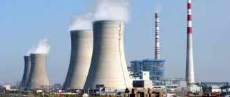
The conversion of natural energy resources into electricity is carried out using special installations operating on various principles. Among them, the most widespread are thermal power plants that use liquid, solid and gaseous organic fuels. They generate more than 70% of the world's electricity and are located close to natural resource deposits. Many thermal power plants produce not only electricity, but also thermal energy.
Types of thermal power plants
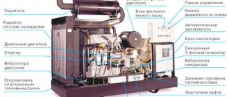
A standard thermal power plant is a whole complex that includes various devices and equipment that convert fuel energy into electricity and heat.
Such installations differ in parameters and technical characteristics, according to which they are classified:
- In accordance with the types and purpose of the supplied electricity, thermal stations can be regional and industrial. Regional installations are known as GRES or IES and are designed to serve all consumers in the region. Power plants that produce heat are called CHP plants. The power of regional stations exceeds 1 million kW. Industrial power plants are designed to supply electricity and heat to specific enterprises and industrial complexes. Their power is significantly less than that of state district power plants and is installed in accordance with the needs of a particular facility.
- All types of thermal power plants operate on different energy sources. First of all, these are ordinary organic resources used by most thermal power plants and petroleum products. The most widespread are coal, natural gas, and fuel oil. The most advanced installations operate on nuclear fuel and are called nuclear power plants - NPPs.
- Power plants that convert heat energy into electricity can be steam turbine, gas turbine, or mixed steam-gas design.
- The technological diagram of steam pipelines of thermal power plants can be different. In block designs, thermal power plants use identical power plants or power units. In them, steam from the boiler is supplied only to its own turbine and, after condensation, it returns to its boiler. Most of the state district power plants (CHPPs) and thermal power plants were built according to this scheme. Another option involves the use of cross connections, when steam from the boilers is supplied to a common manifold - a steam pipeline, which ensures the operation of the entire steam turbines of the station.
- According to the initial pressure parameters, thermal power plants can be with critical and supercritical pressure. In the first case, Russian standards for TPP-CHP are 8.8-12.8 MPa or 90-130 atmospheres. The second option has higher parameters of 23.5 MPa or 240 atmospheres. Such designs use intermediate superheating and a block circuit.
Combined heat and power plants
Combined heat and power plants, being sources of combined generation of electrical and thermal energy, have a significantly higher efficiency factor than CES (up to 75%). This is explained by this. that part of the steam exhausted in turbines is used for the needs of industrial production (technology), heating, and hot water supply.
This steam is either directly supplied for industrial and domestic needs or partially used to preheat water in special boilers (heaters), from which water is sent through the heating network to consumers of thermal energy.
The main difference between the technology of energy production at a thermal power plant in comparison with a CPP is the specificity of the steam-water circuit. Providing intermediate extraction of turbine steam, as well as in the method of energy delivery, according to which the main part of it is distributed at the generator voltage through a generator switchgear (GRU).
The connection of the thermal power plant with other stations of the power system is carried out at increased voltage through step-up transformers. During repairs or emergency shutdown of one generator, the missing power can be transferred from the power system through the same transformers.
To increase the reliability of the CHP operation, sectioning of busbars is provided.
Thus, in the event of an accident on the tires and subsequent repair of one of the sections, the second section remains in operation and provides power to consumers through the remaining energized lines.
According to such schemes, industrial thermal power plants with generators up to 60 MW are built, designed to power local loads within a radius of 10 km.
Large modern thermal power plants use generators with a power of up to 250 MW with a total station power of 500-2500 MW.
Such thermal power plants are built outside the city limits and electricity is transmitted at a voltage of 35-220 kV, a main distribution unit is not provided, all generators are connected into blocks with step-up transformers. If it is necessary to provide power to a small local load near the block heat and power plant, taps from the blocks are provided between the generator and the transformer. Combined plant schemes are also possible, in which the thermal power plant has a main switchgear and several generators are connected using block diagrams.
Thermal power station (general view drawing)
Thermal power station (general view drawing)
The diagram below shows the composition of the main equipment of a thermal power station and the interconnection of its systems. Using this diagram, you can trace the general sequence of technological processes occurring at thermal power plants.
Designations on the TPP diagram:
- Fuel economy;
- fuel preparation;
- boiler;
- intermediate superheater;
- high pressure part of a steam turbine (HPC or HPC);
- low pressure part of a steam turbine (LPT or LPC);
- electric generator;
- auxiliary transformer;
- communication transformer;
- main switchgear;
- capacitor;
- condensate pump;
- circulation pump;
- source of water supply (for example, river);
- low pressure heater (LPH);
- water treatment plant (WPU);
- thermal energy consumer;
- return condensate pump;
- deaerator;
- feed pump;
- high pressure heater (HPH);
- slag removal;
- ash dump;
- smoke exhauster (DS);
- chimney;
- blower fan (DV);
- ash catcher
Description of the TPP technological scheme:
Summarizing all of the above, we obtain the composition of a thermal power plant:
- fuel management and fuel preparation system;
- boiler installation: a combination of the boiler itself and auxiliary equipment;
- turbine installation: steam turbine and its auxiliary equipment;
- water treatment and condensate purification installation;
- technical water supply system;
- ash removal system (for thermal power plants operating on solid fuel);
- electrical equipment and electrical equipment control system.
Fuel facilities, depending on the type of fuel used at the station, include a receiving and unloading device, transport mechanisms, fuel storage facilities for solid and liquid fuels, devices for preliminary fuel preparation (coal crushing plants). The fuel oil facility also includes pumps for pumping fuel oil, fuel oil heaters, and filters.
Preparation of solid fuel for combustion consists of grinding and drying it in a dust preparation plant, and preparation of fuel oil consists of heating it, cleaning it from mechanical impurities, and sometimes treating it with special additives. With gas fuel everything is simpler. Preparation of gas fuel comes down mainly to regulating the gas pressure in front of the boiler burners.
Slag and captured ash are usually removed hydraulically to ash dumps.
When burning fuel oil and gas, ash collectors are not installed.
When fuel is burned, chemically bound energy is converted into thermal energy. As a result, combustion products are formed, which in the heating surfaces of the boiler give off heat to the water and the steam generated from it.
The totality of equipment, its individual elements, and pipelines through which water and steam move form the station’s steam-water path.
In the boiler, the water is heated to saturation temperature, evaporates, and the saturated steam formed from the boiling boiler water is overheated. From the boiler, superheated steam is sent through pipelines to the turbine, where its thermal energy is converted into mechanical energy, transmitted to the turbine shaft. The steam exhausted in the turbine enters the condenser, transfers heat to the cooling water and condenses.
The condensate is pumped out of the condenser by a condensation pump and, after passing through low-pressure heaters (LPH), enters the deaerator. Here it is heated by steam to saturation temperature, while oxygen and carbon dioxide are released from it and removed into the atmosphere to prevent equipment corrosion. Deaerated water, called feedwater, is pumped through high-pressure heaters (HPH) into the boiler.
The condensate in the HDPE and deaerator, as well as the feed water in the HDPE, are heated by steam taken from the turbine. This heating method means returning (regenerating) heat to the cycle and is called regenerative heating. Thanks to it, the flow of steam into the condenser is reduced, and therefore the amount of heat transferred to the cooling water, which leads to an increase in the efficiency of the steam turbine plant.
The set of elements that provide cooling water to the condensers is called the technical water supply system. This includes: a water supply source (river, reservoir, cooling tower), circulation pump, inlet and outlet water pipes. In the condenser, approximately 55% of the heat of the steam entering the turbine is transferred to the cooled water; this part of the heat is not used to generate electricity and is wasted uselessly.
At thermal power plants, there are internal losses of steam and condensate due to the incomplete tightness of the steam-water path, as well as the unrecoverable consumption of steam and condensate for the technical needs of the station. They constitute approximately 1 - 1.5% of the total steam consumption for turbines.
At thermal power plants there may also be external losses of steam and condensate associated with the supply of heat to industrial consumers. On average they are 35 - 50%. Internal and external losses of steam and condensate are replenished with additional water pre-treated in the water treatment plant.
Thus, boiler feed water is a mixture of turbine condensate and make-up water.
The electrical equipment of the station includes an electric generator, a communication transformer, a main switchgear, and a power supply system for the power plant's own mechanisms through an auxiliary transformer.
The control system collects and processes information about the progress of the technological process and the condition of the equipment, automatic and remote control of mechanisms and regulation of basic processes, automatic protection of equipment.
Source: Poleshchuk I.Z., Tsirelman N.M. Introduction to thermal power engineering: Textbook / Ufa State Aviation Technical University. – Ufa, 2003.
Condenser: The exhaust steam is condensed in the condenser by circulating cold water. Here the steam loses its pressure and temperature and it turns back into water. Condensation is necessary because compressing a liquid that is in a gaseous state requires a huge amount of energy compared to the energy required to compress the liquid. Thus, condensation increases the efficiency of the cycle.
Operating principle of a thermal power plant
The basic principle of operation of a thermal power plant is to produce thermal energy from fossil fuels, which is subsequently used to generate electric current.
The concepts of thermal power plant and combined heat and power plant differ significantly from each other. The first installations are so-called pure power plants that produce only electric current. Each of them is also known as a condensing power plant - CES. CHP stands for combined heat and power plant and is a type of thermal power plant. These installations not only generate electricity, but are also thermal, that is, they provide heat to heating and hot water supply systems. This combined use requires special steam turbines with back pressure or an intermediate steam extraction system.
What are the energy sources?
There are many sources of energy. The most interesting are probably the sun and the wind. It seems like nothing is happening, but electricity is being generated. The most technologically advanced methods of production are, without a doubt, nuclear energy and tokamaks, which are still under construction and it is too early to talk about their industrial launch.
There are more extravagant ways to obtain energy. For example, the energy of the Earth, which I talked about in detail earlier. There are even stations that generate energy from the tides. Also a peculiar, but sometimes effective way.
The combination of the above technologies makes it possible to supply an energy source almost anywhere in the world. If anything, it is even possible to set up a floating nuclear power plant, which will provide energy to a small city of 60-100 thousand inhabitants.
The world's first floating nuclear power plant "Akademik Lomonosov".
This is all well and good, but there are more proven ways to obtain energy that require little input, but they require a lot of fuel and are not very environmentally friendly. To generate electricity, they use fossil fuels, which, among other things, may run out, but for now there is enough of it.
An analogue of a solar battery, or how to get energy from the shadows
Coal-fired thermal power plant
Coal has long been one of the main sources of energy in people's daily life and production activities. The wide distribution of this type of fuel became possible due to its availability. In many deposits it is located a few meters from the surface of the earth and can be mined using a cheaper open-pit method. In addition, coal does not require any special storage conditions and is stored in ordinary piles near the site.
Industrial use of coal began at the end of the 18th century. Later, when railway transport appeared, coal became the source of motive power for steam locomotives. It was later used in the first thermal power plants built at the end of the 19th century. Many thermal power plants currently operate on coal.
At the very first power plants, coal was burned by placing it on grates. Fuel loading and slag removal were performed manually. Gradually, these processes were mechanized and coal fell onto the grates from the upper bunker. The grate was set in motion and the waste slag was poured into a special receiver.
Modern thermal power plants no longer use lump coal. Instead, coal dust produced in crushers or mills is loaded into the boilers. Fuel is supplied to the burners by compressed air. Once in the firebox, coal dust mixed with air begins to burn, releasing a large amount of heat.
How does a thermal power plant differ from a combined heat and power plant?
First you need to understand the wording. Many people do not understand how a thermal power plant differs from a combined heat and power plant, and why the same object is often called by both abbreviations.
In fact, it's really about the same thing. A combined heat and power plant (CHP) is a type of thermal power plant (CHP). Unlike the second, the first generates not only electricity, but also heat for heating nearby houses.
60% of the world's energy is produced by thermal power plants . Including the one from which Tesla and other electric vehicles are charged. This is how environmentally friendly it turns out.
CHP plants are more universal, but when everything is fine with heating in houses, simple thermal power plants are built, but often they can be converted into CHP plants by building a couple of additional blocks and laying infrastructure in the form of pipes.
Gas thermal power plants
Second only to coal in importance is natural gas, used by many thermal power plants. This type of fuel has undoubted advantages. Harmful emissions that poison the atmosphere are significantly lower than when burning coal. After combustion, no by-products remain in the form of slag or ash.
The operation of thermal power plants using gas becomes much easier, since in this case the preparation of coal dust is not required. The gas does not require any special preparation and is immediately ready for use. Gas thermal power plants are considered more maneuverable, which is important in situations with changing loads.
The efficiency and efficiency of gas thermal power plants increased significantly when they switched to operating mode with the cycle of combined cycle plants. The fuel is burned not in a boiler, but in a gas turbine. Such installations are intended only for gas and cannot operate on coal dust.
Five of the most powerful thermal power plants in the world
The championship belongs to the Chinese thermal power plant Tuoketuo with a capacity of 6600 MW (5 power units x 1200 MW), occupying an area of 2.5 square meters. km. It is followed by its “compatriot” - the Taichung Thermal Power Plant with a capacity of 5824 MW. The top three is closed by the largest in Russia Surgutskaya GRES-2 - 5597.1 MW. In fourth place is the Polish Belchatow Thermal Power Plant - 5354 MW, and fifth is the Futtsu CCGT Power Plant (Japan) - a gas thermal power plant with a capacity of 5040 MW.
Surgut GRES-2
Other types of fuel for thermal power plants
In addition to traditional fuels, thermal power plants also use other energy sources in their work. One such energy resource is fuel oil, which was used in many power plants in the second half of the 20th century.
In modern conditions, the price of petroleum products has increased significantly, so fuel oil has ceased to be the main fuel. It is partially used by coal-fired power plants for kindling. The performance qualities of fuel oil are similar to those of natural gas, however, when it is burned, large quantities of sulfur oxide are released, which pollutes the environment.
In the 20th century, some thermal power plants operated on peat. Currently, this resource is practically not used due to low efficiency compared to gas and coal. Diesel fuel installations are used in small facilities where significant amounts of electricity are not required. Basically, they are intended for remote areas located at a considerable distance from centralized power supply networks.
Advantages and disadvantages of thermal power plants
Advantages:
Lower initial cost compared to other generating stations. Less land required compared to hydroelectric power plant. Fuel (i.e. coal) is cheaper. The cost of generation is lower than that of diesel power plants.
Flaws:
It pollutes the atmosphere due to the production of large amounts of smoke. This is one of the causes of global warming. The overall efficiency of the thermal power plant is low (less than 30%).
CHP efficiency
A huge amount of heat is lost at different stages of the plant. Most of the heat is lost in the condenser. This is why the efficiency of thermal power plants is quite low.
Thermal efficiency. The ratio of the “thermal equivalent of mechanical energy transferred to the turbine shaft” to the “heat of combustion of coal” is called thermal efficiency.
The thermal efficiency of modern thermal power plants is about 30%. This means that when coal burns 100 calories of heat, the turbine shaft will have mechanical energy equivalent to 30 calories. Overall Efficiency: The ratio of "thermal equivalent of electrical power" to "heat of combustion of coal" is called overall efficiency. The overall efficiency of the thermal plant is about 29% (slightly less than thermal efficiency).
The impeller blades of this steam turbine are clearly visible.
- » onclick=»window.open(this.href,'win2′,'status=no,toolbar=no,scrollbars=yes,titlebar=no,menubar=no,resizable=yes,width=640,height=480,directories =no,location=no'); return false;" rel=”nofollow”> Print
Date Category: Physics
The impeller blades of this steam turbine are clearly visible.
A thermal power plant (CHP) uses the energy released by burning fossil fuels—coal, oil, and natural gas—to convert water into high-pressure steam. This steam, having a pressure of about 240 kilograms per square centimeter and a temperature of 524°C (1000°F), drives the turbine. The turbine spins a giant magnet inside a generator, which produces electricity.
Modern thermal power plants convert about 40 percent of the heat released during fuel combustion into electricity, the rest is discharged into the environment. In Europe, many thermal power plants use waste heat to heat nearby homes and businesses. Combined heat and power generation increases the energy output of the power plant by up to 80 percent.
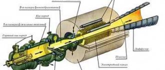
Steam turbine plant with electric generator
A typical steam turbine contains two groups of blades. High-pressure steam coming directly from the boiler enters the flow path of the turbine and rotates the impellers with the first group of blades. The steam is then heated in the superheater and again enters the turbine flow path to rotate impellers with a second group of blades, which operate at a lower steam pressure.
Sectional view
A typical thermal power plant (CHP) generator is driven directly by a steam turbine, which rotates at 3,000 revolutions per minute. In generators of this type, the magnet, also called the rotor, rotates, but the windings (stator) are stationary. The cooling system prevents the generator from overheating.
Power generation using steam
At a thermal power plant, fuel burns in a boiler, producing a high-temperature flame. The water passes through the tubes through the flame, is heated and turns into high-pressure steam. The steam spins a turbine, producing mechanical energy, which a generator converts into electricity. After leaving the turbine, the steam enters the condenser, where it washes the tubes with cold running water, and as a result turns into a liquid again.
Oil, coal or gas boiler
Inside the boiler
The boiler is filled with intricately curved tubes through which heated water passes. The complex configuration of the tubes allows you to significantly increase the amount of heat transferred to the water and, as a result, produce much more steam.
In backpressure turbines, all exhaust steam is used for technological purposes (cooking, drying, heating). The electrical power developed by a turbine unit with such a steam turbine depends on the need of the production or heating system for heating steam and changes with it. Therefore, a backpressure turbine unit usually operates in parallel with a condensing turbine or power grid, which covers the resulting electricity shortage.
Cogeneration steam turbines are used to simultaneously produce electrical and thermal energy. But the main end product of such turbines is heat. Thermal power plants that have cogeneration steam turbines are called combined heat and power plants (CHP). Cogeneration steam turbines include turbines with back pressure, with controlled steam extraction, as well as with extraction and back pressure.
In backpressure turbines, all exhaust steam is used for technological purposes (cooking, drying, heating). The electrical power developed by a turbine unit with such a steam turbine depends on the need of the production or heating system for heating steam and changes with it. Therefore, a backpressure turbine unit usually operates in parallel with a condensing turbine or power grid, which covers the resulting electricity shortage.
In turbines with controlled extraction, part of the steam is removed from 1 or 2 intermediate stages, and the rest of the steam goes to the condenser. The pressure of the extracted steam is maintained within specified limits by the control system. The extraction location (turbine stage) is selected depending on the required steam parameters.
In turbines with extraction and back pressure, part of the steam is removed from 1 or 2 intermediate stages, and all exhaust steam is directed from the exhaust pipe to the heating system or to network heaters.
For some turbines, it is possible to operate at “deteriorated vacuum” - up to 20 kPa or more.
A type of thermal power plant that not only produces electricity, but is also a source of thermal energy in the central heating system
A combined heat and power plant (CHP) is a type of thermal power plant that not only produces electricity, but is also a source of thermal energy in centralized heat supply systems (in the form of steam and hot water, including for providing hot water supply and heating of residential and industrial facilities).
The thermal power plant is structurally designed like a condensing power plant (CPS, State District Power Plant).
The main difference between CHP and CES is the ability to take away part of the thermal energy of steam after it has generated electrical energy.
Depending on the type of steam turbine, there are various steam extractions that allow you to extract steam with different parameters from it.
CHP turbines allow you to regulate the amount of extracted steam.
The selected steam is condensed in network heaters and transfers its energy to network water, which is sent to peak water heating boilers and heating points.
At a thermal power plant it is possible to shut off the thermal extraction of steam; in this case, the thermal power plant becomes a conventional CES.
This makes it possible to operate the CHP plant according to 2 load schedules:
thermal - the electrical load strongly depends on the thermal load (thermal load is a priority);
electrical - the electrical load does not depend on the thermal load, or there is no thermal load at all, for example, in the summer (priority - electrical load).
Combining the functions of generating heat and electricity (cogeneration) is beneficial, since the remaining heat, which is not involved in the operation of the CPP, is used for heating.
This increases the calculated efficiency in general (35-43% for CHP plants and 30% for CPPs), but does not indicate the efficiency of CHP plants.
The main indicators of efficiency are the specific electricity generation from heat consumption and the efficiency of the IES cycle.
When constructing a thermal power plant, it is necessary to take into account the proximity of heat consumers in the form of hot water and steam, since heat transfer over long distances is not economically feasible.
Based on the type of connection between boilers and turbines, combined heat and power plants can be:
non-block (with cross-links).
At block thermal power plants, boilers and turbines are connected in pairs (sometimes a double-block diagram is used: 2 boilers per 1 turbine).
Such units usually have high electrical power: 100-300 MW.
The cross-coupled design allows steam to be transferred from any boiler to any turbine, which increases the flexibility of plant control.
However, this requires the installation of large steam pipelines along the main station building.
In addition, all boilers and all turbines combined into a circuit must have the same nominal steam parameters (pressure, temperature).
If the main equipment of different parameters was installed at the thermal power plant in different years, there should be several cross-linked circuits.
To force changes in steam parameters, a reduction-cooling device (RCD) can be used.
According to the type of steam-producing installations, thermal power plants can be:
with steam boilers,
with steam and gas plants,
with nuclear reactors (nuclear thermal power plant).
There may also be thermal power plants without steam-producing units - with gas turbine units.
Since thermal power plants are often built, expanded and reconstructed over decades (which is associated with a gradual increase in heat loads), many stations have installations of different types.
Steam boilers of thermal power plants also differ in the type of fuel:
Turbines are classified according to the type of heat output:
with adjustable cogeneration steam extraction (turbines manufactured in Russia have the letter “T” in their designation, for example, T-110/120-130),
with controlled production steam extractions (“P”),
with back pressure (“P”).
There are usually 1-2 regulated selections of each type.
In this case, the number of unregulated extractions used to regenerate heat inside the thermal circuit of the turbine can be any (as a rule, no more than 9, as for the T-250/300-240 turbine).
The pressure in production extractions (nominal value is approximately 1-2 MPa) is usually higher than in district heating (approximately 0.05-0.3 MPa).
The term “back pressure” means that the turbine does not have a condenser, and all waste steam is used for the production needs of the enterprises served.
Such a turbine cannot operate if there is no backpressure steam consumer.
Heating turbines (type “T”) can operate in a similar mode at full heat load: in this case, all the steam goes into the heating exhaust, but the pressure in the condenser is maintained slightly more than nominal (usually no more than 12-17 kPa).
For some turbines, it is possible to operate at “deteriorated vacuum” - up to 20 kPa or more.
In addition, steam turbines with a mixed type of extraction are produced:
with controlled heating and production extractions (“PT”),
with adjustable extractions and back pressure (“PR”), etc.
At a thermal power plant, turbines of various types can operate simultaneously, depending on the required combination of thermal loads.
In an actual cycle, steam expansion in the turbine occurs along the 1-2′ line, i.e., only part of the heat release is used, A qK
— internal energy losses in the turbine.
Fuel and heated air enter the boiler race (Kt). The gases formed during fuel combustion are sucked out of the boiler and thrown out by a smoke exhauster (the height of the smoke columns is
Rice.
2.2. IES diagram:
E - economizer; PN, KP, CP - feed, condensation, circulation pumps
Passing the main amount of steam through the condenser leads to the fact that a significant part of the thermal energy (up to 70%) is uselessly carried away by the circulating water.
IES will be located near energy sources (coal, gas, fuel oil). The unit capacity of the units (units) is 500.1200 MW, while the power of the ES is 2000.3600 MW. A special feature of IES is the low maneuverability of the blocks. So, turning the turbine and loading the block from the “cold state” takes from 3 to 10 hours.
The heat balance of the IES is shown in Fig. 2.3.
Rice.
2.3. Thermal balance of IES The main disadvantage of IES is its low efficiency.
Combined heat and power plants operate on the same principle as CES, but at the same time, the exhaust steam from the turbine is diverted to electric heaters (HS).
Consumers receive heat from network heaters (NH). The greater the extraction of steam from the boiler for heating purposes, the less heat is lost with the circulating water, and the efficiency of the station will be greater.
CHP plants are built near heat consumers and therefore they operate on imported fuel; most of the energy is consumed in the surrounding area. The efficiency of thermal power plants is much higher than that of IES (for IES the efficiency is 25.40%, for thermal power plants - 60.70%).
The design diagram of the IES is shown in Fig. 2.4.
Rice.
2.4. Diagram of a coal-fired condensing power plant:
I
— fuel bunker;
2
— dust preparation device;
3
— air supply;
- 4 - boiler furnace; 5 -
drum;
b
- convective shaft of the boiler; 7 - chimney; - 8 — turbine high-pressure motor; 9 —
low pressure turbine;
K)
- electric generator;
11
— power plant busbars;
12 -
reservoir;
13
- pump;
14 -
capacitor;
15 -
feed pump
In an actual cycle, steam expansion in the turbine occurs along the 1-2′ line, i.e., only part of the heat release is used, A qK
— internal energy losses in the turbine.
Hp at a temperature of 600 °C and a pressure of 30 MPa is transferred to the nozzles of the turbine diaphragms, which act as a converter of the internal energy of steam into the kinetic energy of the ordered movement of molecules.
Rice.
2.5. Thermal diagram of the Rankine cycle
Gas turbine plants
(/THAT)
Gas turbines use a mixture of combustion products with air or heated air at high pressure and high temperature as a working fluid. The thermal energy of gases is converted into kinetic energy of rotation of the turbine rotor. But the principle of energy conversion of G'GUs is no different from steam ES. The GTU diagram is shown in Fig. 2.6.
Rice.
2.6. Gas turbine installation diagram
Scheme of mini-CHP using wood waste
Waste from the timber processing industry, agriculture and agro-industrial complex is a valuable energy resource that will allow you to meet the enterprise's needs for electricity and heat for heating and technological processes.
The construction of a thermal power plant or mini thermal power plant using waste is an excellent solution that will allow you to use waste from all wood processing enterprises (pulp and pulp and paper mills, plywood, sawmills), as well as agricultural and livestock waste as fuel. For example, the construction of mini-CHP using wood waste is widespread.
“First Engineer” supplies, and, if the Customer so desires, localizes the production of metal-intensive boiler equipment, designs and constructs biofuel energy sources at KABLITZ boiler plants (Germany):
CHP and mini CHP using wood waste with steam turbines
- The source of thermal and electrical energy is autonomous and absolutely reliable
- Effective recycling of production waste
- Reducing energy costs for your own needs
Technical solution
Biomass CHP with steam turbines will allow you to:
- Eliminate the costs of purchasing electricity, steam and hot water from external suppliers
- Ensure stable energy supply and increase the category of energy supply
- Get additional profit by selling energy to third-party consumers
- Reduce the area of territories used for storing production waste
- Minimize the risks associated with the storage of production waste (environmental pollution, fire hazard, etc.)
Scheme of mini-CHP using wood waste
Technological thermal oil unit (TMU) on biomass
- The heat source is autonomous and economical
- Efficient disposal
- Reducing thermal energy costs
Technical solution
- Unit thermal energy output up to 80 MW
- Required thermal oil heating level 315 °C
- Organic and synthetic coolants
- Single pass thermal oil heat exchangers
- Control of oil flow in each individual pipeline circuit
- Required flue gas temperature level (including the use of a flue gas condenser)
TMU using biomass will allow you to:
- Eliminate the cost of purchasing energy from external suppliers
- Ensure stable heat supply to process consumers
- Reduce the impact on the environment by reducing the areas used for storing production waste and minimizing associated risks.
Biofuel hot water boiler house
- Autonomous heat source in close proximity to the consumer
- Effective disposal of wood waste
Technical solution
- Unit thermal energy output up to 50 MW
- Heating water up to 150 °C
- Mixed water-gas tube boilers and all water tube boilers
- Combustion solution for fuels with low ash melting point (bark, contaminated waste)
- Required flue gas temperature level (including the use of a flue gas condenser)
A hot water boiler house using biofuel will allow:
- Eliminate costs for purchasing heat energy from external suppliers
- Ensure stable heat supply to the enterprise using internal resources and with minimal heat loss
- Recycle up to 100% of wood or plant waste from production
- Promote conservation of natural resources.
“First Engineer” is a system integrator and partner of the leading European manufacturer of boiler equipment Richard Kablitz GMbH (Germany) in the Russian Federation.
- We will help you assess the feasibility and capacity of a CHP plant, a mini CHP plant or a biofuel boiler house for the needs of your enterprise;
- We will offer the optimal technical solution based on your requirements and design a boiler house, CHP plant or mini-CHP;
- we will carry out the construction of a boiler house, thermal power plant or mini thermal power plant on a turnkey basis;
- We will provide warranty and post-warranty service for the constructed facility and service support.
We will offer the optimal technical solution based on your requirements and prepare a design for a thermal power plant, mini thermal power plant or biofuel boiler house.
Localization
The production of metal-intensive Kablitz equipment for thermal power plants, mini thermal power plants or boiler houses according to the manufacturer’s drawings is carried out at leading Russian specialized enterprises in close proximity to the customer.
- We save up to 20% of your budget by reducing production costs, logistics, customs duties and reducing the impact of exchange rates;
- without loss of quality: the development of technical solutions for localization and production are carried out under the control of Richard Kablitz GmbH.
Our solutions for CHP plants
- allow you to completely recycle waste from enterprises (wood processing, agro-industrial complex, pulp and paper mill);
- meet modern requirements for technical and economic indicators, reliability and standards for emissions of harmful substances into the environment;
- can be implemented in a short time and allow the thermal power plant to be put into commercial operation and connected to existing engineering and technological communications during periods of shutdown repairs of the enterprise to eliminate the impact on the operation of the enterprise.
You too can start: just call or write to us to get technical advice from a specialist from the First Engineer bioenergy department.
Types of thermal power plants begin with condensing ones. Such thermal power plants are used exclusively for generating electricity. Most often, it accumulates without immediately spreading. The condensation method provides maximum efficiency, so similar principles are considered optimal. Today, in all countries, there are separate large-scale facilities that supply vast regions.
Thermal power plant efficiency
The main indicator of any thermal power plant is its efficiency. For example, for coal-fired thermal power plants there is a thermal efficiency determined by the amount of coal required to generate 1 kWh of electricity. If at the beginning of the 20s of the last century this figure was 15.4 kg, then in the 60s it dropped to 3.95 kg. Subsequently, coal consumption again increased slightly to 4.6 kg.
The reason for this increase was gas scrubbers, dust and ash collectors, due to which the coal-fired power plant reduced its power output by 10%. Many stations use cleaner coal, which has also led to increased fuel consumption.
The percentage expression of the thermal efficiency of a thermal power plant is no more than 36%, which is associated with high heat losses caused by exhaust gases during combustion. Nuclear power plants with low temperatures and pressure have even lower thermal efficiency - 32%. The highest rate is for gas turbine plants equipped with waste heat boilers and additional steam turbines. The efficiency of power plants with such equipment exceeds 40%. This indicator completely depends on the operating temperatures and steam pressure.
History of thermal energy and development prospects
The first thermal power plant was built by the German engineer Sigmund Schuckert in Bavaria in 1878. With its help, the grotto in the garden of Linderhof Castle was illuminated. In 1882, a power station was commissioned in London, which was used for electric lighting, and in New York (500 kW). They used piston steam engines.
The invention of the steam turbine made it possible to build larger and more efficient plants, and from 1905 thermal power plants began to be built only with turbines.
In Russia, the first public thermal power plant with a capacity of 35 kW was built in 1883 in St. Petersburg. It was intended to supply electricity to illuminate Nevsky Prospekt. Moscow GES-1 (city power plant) appeared in 1897. Its power was 3.7 mW.
The structure of thermal power plants in Russia today:
- with steam turbines - 79% of the total capacity;
- with combined cycle units – 15.5%;
- with gas turbine units – 4.8%;
- with diesel and gas piston units – 0.7%.
The transition to generating electricity from renewable sources is not so simple, although this is the desired direction of development of the electric power industry for humanity. In the near future, it will be impossible to abandon thermal energy, and it will retain its dominant role.
The main direction of development of this industry is the development of advanced technologies that will reduce the amount of harmful emissions into the atmosphere, as well as increase the efficiency of thermal power plants.
Mechanical part of the station
The design and principle of operation of a thermal power plant in its mechanical part is associated with the operation of the rotor. The steam that comes from the turbine has very high pressure and temperature. Because of this, high internal energy of steam is created, which flows from the boiler into the turbine nozzles. Jets of steam, passing through the nozzle in a continuous flow, at high speed, which is often even higher than sound speed, act on the turbine blades. These elements are rigidly fixed to the disk, which, in turn, is closely connected to the shaft. At this point in time, the mechanical energy of the steam is converted into the mechanical energy of the rotor turbines. If we talk more precisely about the principle of operation of thermal power plants, then the mechanical impact affects the rotor of the turbogenerator. This is due to the fact that the shaft of a conventional rotor and generator are tightly coupled to each other. And then there is a fairly well-known, simple and understandable process of converting mechanical energy into electrical energy in a device such as a generator.
Steam movement after the rotor
After the water vapor passes through the turbine, its pressure and temperature drop significantly, and it enters the next part of the station - the condenser. Inside this element, the vapor is converted back into liquid. To perform this task, there is cooling water inside the condenser, which is supplied there through pipes running inside the walls of the device. After the steam is converted back into water, it is pumped out by a condensate pump and enters the next compartment - the deaerator. It is also important to note that the pumped water passes through regenerative heaters.
The main task of the deaerator is to remove gases from the incoming water. Simultaneously with the cleaning operation, the liquid is heated in the same way as in regenerative heaters. For this purpose, the heat of the steam is used, which is taken from what goes into the turbine. The main purpose of the deaeration operation is to reduce the oxygen and carbon dioxide content in the liquid to acceptable values. This helps reduce the rate of corrosion on the paths through which water and steam are supplied.
District heating
At some thermal power plants, their design may include a system that handles heating of the power plant itself, as well as the adjacent village, if there is one. To the network heaters of this installation, steam is taken from the turbine, and there is also a special line for condensate removal. Water is supplied and discharged through a special pipeline system. The electrical energy that will be generated in this way is removed from the electrical generator and transmitted to the consumer, passing through step-up transformers.