Electricity is the only type of energy that can be easily transmitted over long distances and then converted into mechanical, thermal or light radiation. Electricity itself can also be obtained in different ways: chemical, thermal, mechanical, photoelectric, etc. But it is the mechanical method, which is based on the use of generators, that has proven to be the most effective. Among these sources of electricity, the synchronous alternating current generator has found widespread use.
Almost all electricity used in everyday life and at work is generated by generators of this type. They deserve to take a closer look at their design and understand the operating principle of these amazing synchronous machines.
Device
The design of synchronous generators uses two main working parts - a rotating rotor and a stationary stator. Permanent magnets or field windings are located on the rotor shaft. Magnets have a toothed shape, with opposite poles.
Brushless generators.
The stator windings are placed in such a way that their cores coincide with the protrusions of the magnetic poles of the rotor, or with the cores of the rotor coils. The number of magnet teeth usually does not exceed 6. With this design, the generated current is removed directly from the stator windings. In other words, the stator acts as an armature.
In principle, permanent magnets can be placed on the stator, and the working windings, in which the EMF will be induced, can be placed on the rotor. This will not change the performance of the generator, but it will require rings and brushes to relieve voltage from the armature windings, and this is most often not rational.
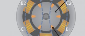
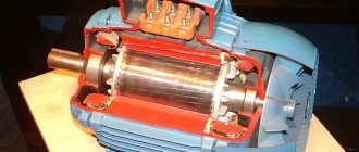
A schematic representation of a brushless generator without field windings is shown in Fig. 1.
Rice. 1. Model of a generator with a magnetic rotor
Explanation:
- device diagram;
- diagram of the location of the magnetic poles on the anchor. Here, the letters NS denote a coaxial magnet with poles, and the letter R denotes the steel magnetic core of the rotor in the form of claw-shaped tips.
- cutaway model of the generator. The terminals of the stator phase windings are connected in a star.
Synchronous machines with inductors.
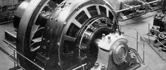
Note that permanent magnets are used as a rotor in low-power alternators. In powerful electrical machines, inductor windings with independent excitation are always used. The independent power source is a low-power DC generator mounted on the shaft of a synchronous motor.
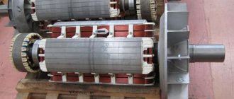
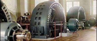
There are designs of low and medium power synchronous generators with self-exciting windings. To excite the inductor, the rectified current of the phase windings is supplied through brushes to the rings located on the stator shaft. The structure of such an alternator is shown in Fig. 2.
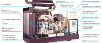
Rice. 2. Structure of a medium power synchronous generator
Pay attention to the presence of brushes that are supplied with power from an independent source.
According to the number of phases, synchronous generators are divided into:
- single-phase;
- two-phase;
- three-phase.
Based on the design of the rotor, generators with salient and non-salient poles can be distinguished. The non-salient pole rotor has no protrusions, and the armature wire coils are hidden in the stator slots.
According to the method of connecting the phase windings, three-phase generators are distinguished:
- connected via Tesla's six-wire system (not found practical application);
- "star";
- "triangle";
- a combination of six windings connected in the form of one “star” and “triangle”. This compound is also called “Slavyanka”.
The most common connection is a star connection with a neutral wire.
Anchor reaction
When the output is connected to an external load, electric current flows in the stator windings. The resulting magnetic field is superimposed on the field created by the rotor.
Armature reaction under different types of load
With an active load, the current and EMF are in phase (shown in the figure above - a). It becomes maximum if the rotor poles are located opposite the armature windings. The main magnetic flux and the one generated from the armature reaction are perpendicular and, when superimposed, form a slightly larger resulting flux, which increases the emf.
An inductive load leads to a decrease in EMF, since the flows are directed in the opposite direction (shown in the figure above - b).
The capacitive load causes the flow directions to coincide, as a result of which the EMF increases.
Increasing the load results in a larger armature reaction resulting in a change in the output voltage, which is undesirable. In practice, this process is controlled by changing the excitation, which reduces the degree of influence of the armature reaction on the main field.
Principle of operation
Let's consider the principle of current generation using the example of a contour frame placed between the magnetic poles. (Fig. 3)
Rice. 3. Diagram explaining the principle of operation of the generator
If you force the frame to rotate (in the direction of the arrows), it will cross the magnetic lines of force. In this case, according to the law of electromagnetic induction, an electric current is induced in the frame, which appears when a load is connected to the brushes. Its direction can be determined by the gimlet rule. In the diagram, the direction of the current is shown by black arrows.
Note that in frame sections ab and cd the current moves in opposite directions. These directions change when sections of the frame move from one pole to another pole of the magnet. If each terminal of the frame is connected to a separate ring (in the figure they are connected to the collector!), then at the output we will get alternating current.
The magnitude of the current is proportional to the speed of rotation of the rotor. In addition, alternating current is characterized by another parameter – frequency. This value directly depends on the shaft rotation speed.
The frequency of current in electrical networks is strictly observed. In Russia and in a number of other countries it is 50 Hz, that is, 50 vibrations per second.
This parameter is quite easy to calculate from the following considerations: for one revolution of the frame (or two-pole magnet), one change in the direction of the current occurs. If the shaft of a synchronous generator makes 1 revolution per second, then the frequency of the alternating current will be 1 Hz. To obtain a frequency of 50 Hz, it is necessary to provide 50 stator revolutions per second or 3000 rpm.
As the number of poles increases, the specified frequency is maintained by reducing the stator rotation speed. (inversely proportional relationship). So, for a four-pole stator (the number of poles is twice as large), in order to maintain a frequency of 50 Hz, the shaft rotation speed must be reduced by half. Accordingly, if 6 poles are used, then the shaft rotation speed should decrease three times - to 1000 rpm.
Note that in some countries, such as the USA, Japan, etc., there are other standards - 60 Hz, and variable 400 Hz is used, for example, in the on-board network of modern aircraft.
Types of synchronous units
There are the following types of synchronous generators:
- Hydro - in it the rotor has a difference due to the presence of pronounced poles, is used in the production of electricity, and operates at low speeds.
- Turbo - has differences in the non-salient pole structure of the generator, is produced from turbines of different types, the speed of revolutions is quite high, reaching about 6000 revolutions per minute.
- Synchronous compensator - this unit supplies reactive power and is used to improve the quality of electricity in order to stabilize the voltage.
- Double power asynchronous unit - the device of this type of generator is that it connects both rotor and stator windings from the supplier of currents with different frequencies. An asynchronous work schedule is created. It is also distinguished by its stable operating schedule and the fact that it converts different phase currents and is used to solve problems with a narrow specialization.
- Bipolar impact unit - works in a short circuit schedule, acts briefly, in milliseconds. Also tests high voltage devices.
Frequency regulation
You can achieve the required frequency parameters in 2 ways:
- Construct a generator with a certain number of electromagnet poles.
- Ensure the appropriate design shaft speed.
For example, in low-speed hydraulic turbines rotating at a speed of 150 rpm. to regulate the frequency, the number of poles of synchronous generators is increased to 40. At diesel power plants, at rotation speeds of 750 rpm, the optimal number of poles is 8.
Types of units
The synchronous generator (motor) is divided into several models, which are designed for various purposes:
- Stepper (pulse) – used for drives of mechanisms with a start-stop operating cycle or continuous motion devices with a pulse control signal (counters, tape drives, CNC machine drives, etc.).
- Gearless – for use in autonomous systems.
- Non-contact - used to operate as power plants on ships of the sea and river fleet.
- Hysteresis - used for time counters, in inertial electric drives, in automatic control systems;
- Induction motors – for supplying electrical installations.
EMF regulation
Due to changes in the parameters of active loads, there is a need to equalize the rated voltages. Despite the fact that the induced emf of a synchronous generator is related to the rotor rotation speed, however, due to the requirements for maintaining a stable frequency, this parameter cannot be changed in this way. But the parameters of magnetic induction can be changed by reducing or increasing the magnetic flux, which depends on the number of turns of the inductor winding and the magnitude of the excitation current.
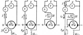
Regulation is carried out by connecting additional rheostats, electronic circuits to the excitation coil circuit, or by adjusting the current of the exciter generator (Fig. 4). In the case of using alternators with permanent magnets, the voltage in such devices is regulated by external stabilizers.
Rice. 4. Voltage regulation circuit
Due to their low weight and excellent current characteristics, synchronous alternating current generators are used in all modern cars. Since the car's on-board network uses direct current, car generator designs are equipped with a three-phase rectifier. For rectified alternating currents, the frequency does not matter, but the voltage must be stable. This is achieved using external electronic devices. Figure 5 shows an electrical diagram for connecting the generator to the on-board network of a modern car.
Rice. 5. Connection diagram of the generator to the vehicle’s on-board network
Automatic field extinguishing machines (AGP)
Field damping machines are designed for switching the excitation winding circuits of turbo and hydrogen generators that have slip rings on the rotor, as well as for field damping of these machines.
Optimal conditions for intensively reducing the rotor current to zero are provided by discharging the excitation winding onto a nonlinear resistor, the resistance of which varies in inverse proportion to the current value.
Thanks to the special design of the ring arc extinguishing grid of the field extinguishing machine, the arc burning in it has the current-voltage characteristic of a nonlinear resistor, which ensures minimal field extinguishing time and a safe voltage level on the rotor rings. The main characteristics of the AGP produced by Elektrosila JSC are presented in Table 5.2.
Application
Synchronous alternating current generators have one important feature: they can be synchronized with other similar electrical machines. In this case, the synchronous speeds and EMF of parallel-connected alternators coincide, and the phase shift is zero. This circumstance allows the devices to be used in industrial energy and to connect backup generators when the rated power is exceeded during peak load hours.
Three-phase traction generators are used on diesel locomotives. Alternating currents to power motors are rectified by semiconductor devices. Today, Russia is already producing diesel locomotives based on asynchronous electric motors that do not require current rectification. In braking mode they operate as asynchronous generators.
Synchronous generators are installed on hybrid vehicles in order to combine the thrust of the internal combustion engine and the power of traction electric motors. By developing active power at rated loads, they save expensive fuel.
There are many other applications. For example, mobile mini-power plants, household current generators, like a single-phase motor, etc.
Excitation structures
Any turbo, hydro, diesel generators, synchronous compensators, motors produced at the moment are equipped with the latest semiconductor structures, such as excitation of synchronous generators. These structures use the method of rectifying three-phase alternating currents of high or industrial frequency exciters or the voltage of the excited unit.
The design of the generator is such that the excitation structures can provide such unit operating parameters as:
- The first stage of excitement, that is, the initial stage.
- Idle work.
- Connecting to the network using precise synchronization or self-synchronization.
- Work in the energy structure with existing loads or overloads.
- The excitation of synchronous devices can be forced according to criteria such as voltage and current, having a specified multiplicity.
- Electric braking of the device.
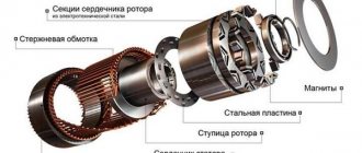
Main structural elements
The stator design includes a housing, inside of which there is a core, or a package assembled from sheets of electrical steel of a special shape. The quality of the electric current is influenced by such factors as: the integrity of the sheets in the package (they can be solid or composite), the quality and material of the winding. Copper enamel wire is used for winding, and in cheap devices it is possible to replace copper with aluminum.
Rotors are manufactured salient-pole or non-salient-pole.
- Salient pole rotors are designed for synchronous generators operating with internal combustion engines at low speeds of 1500 and 3000 rpm.
- Non-salient pole rotors are in demand in high-speed (more than 3000 rpm) high-power alternating electric current mechanisms. They are usually placed on the same shaft as steam turbines. Such SGs are called “turbogenerators”.
In a synchronous generator operating under load, the stator magnetic field, superimposed on the main rotor magnetic field created by the field winding, weakens or strengthens it. The effect of the magnetizing force of the armature on the magnetic excitation field of the generator rotor is called the armature reaction.
The connection diagram for a synchronous generator is shown in Fig. 1.
A synchronous generator works as follows. The generator rotor is driven by the prime mover at rated speed, which is kept constant by the prime mover's automatic speed controller. The generator is excited by supplying excitation current to the rotor winding.
Promotional offers based on your interests:
In a synchronous generator operating under load, the stator magnetic field, superimposed on the main rotor magnetic field created by the field winding, weakens or strengthens it. The effect of the magnetizing force of the armature on the magnetic excitation field of the generator rotor is called the armature reaction.
The anchor reaction can be transverse or longitudinal. In transverse reaction, the stator field demagnetizes the advancing edge of the poles and magnetizes the running edge of the poles. The longitudinal reaction can be longitudinally demagnetizing or longitudinally magnetizing. In the first case, the magnetic flux of the armature is directed towards the flux of the poles along their axis, in the second case, according to the flux of the poles also along their axis.
The armature reaction depends on the nature of the load and has a great influence on the operation of the synchronous generator. With a purely active load, the armature reaction will be transverse, and with purely inductive and purely capacitive loads, it will be longitudinally demagnetizing and longitudinally magnetizing, respectively. Conventional generators operate on a mixed load, most often inductive and active.
The need to regulate the excitation current is caused by frequent changes in the nature and magnitude of the load.
Independent excitation can be carried out from an external alternating voltage source.