Small-sized AC contactors for general industrial use KMI for load currents from 9 to 95 A are designed for starting, stopping and reversing asynchronous electric motors with a squirrel-cage rotor for voltages up to 660 V (application category AC-3), as well as for remote control of lighting circuits and heating circuits and various low-inductive loads (application category AC-1). All versions for load currents up to 40 A have one group of making or breaking additional contacts. Versions for load current over 40 A - two groups (closing and breaking).
The scope of application of small-sized contactors of the KMI series is the control of fans, pumps, thermal curtains, furnaces, overhead cranes, machine tools, lighting, and in automatic transfer transfer systems (ATS).
Due to the possibility of installation in a protective shell, KMI contactors can be installed in unfavorable environments, with a high degree of air pollution and high humidity. A wide range of additional assembly units allows contactors to be integrated into complex automated production processes.
KMI contactors are alternating current electromagnetic devices, the magnetic systems of which are divided into two parts: a fixed part, elastically fixed in a plastic base, and a moving part with contacts for switching the power circuit.
Decoding KMI 10910, markings.
KMI - small-sized contactor produced by IEK (Interelektrokomplekt LLC); 1 — designation of the housing size; 1 - rated current of main contacts 9, 12, 18 A; 2 - rated current of the main contacts 25, 32 A; 3 - rated current of main contacts 40, 50 A; 4 - rated current of main contacts 65, 80, 95 A; 9 - rated value of switched current; 09 - 9A; 12 - 12A; 18 - 18A; 25 - 25A; 32 - 32A; 40 - 40A; 50 - 50A; 65 - 65A; 80 - 80A; 90 - 90A; 1 - version of contactors; 1 - irreversible (without shell); 2 - irreversible with thermal relay (without shell); 3 - reversible (without shell); 4 - reversible with thermal relay (without shell); 5 - irreversible (in a shell); 6 - irreversible with thermal relay (in a shell; - presence of additional contacts; 0 - one group of normally open contacts; 1 - one group of normally open contacts; 2 - one group of normally open contacts and one group of normally open contacts;
Technical characteristics of KMI 10910
| Nominal control circuit supply voltage Us AC 50 Hz: | 230 V |
| Rated operating current Ie 400 V: | 9 A |
| Type of connection for auxiliary circuits: | Screw connection |
| Number of auxiliary standards open-NO contact: | 1 |
| Rated slave AC voltage Ue: | 230; 400; 660 V |
| Rated insulation voltage Ui: | 660 V |
| Nominal impulse voltage: | 6 kV |
| Conditional thermal current Ith at C-1: | 25 A |
| Rated power at AC-3 230 V: | 2.2 kW |
| Rated power at AC-3 400 V: | 4.0 kW |
| Rated power at AC-3 660 V: | 5.5 kW |
| Max short-term load: | 162 A |
| Conditional short circuit current Inc: | 1000 A |
| Overcurrent protection - fuse gG: | 10 A |
| Power dissipation at Ie AC-3: | 0.2 W |
| Power dissipation at Ie AC-1: | 1.56 W |
| Torque: | 1.2 Nm |
| Control voltage ranges when activated Uc: | 0,8. 1,1 |
| Flexible cable without tip2: | 1.0. 2.5 mm |
| Control voltage ranges when releasing Uc: | 0,3. 0,6 |
| Response time when closing: | 12.22ms |
| Rigid cable without tip2: | 1.5. 4 mm |
| Response time when opening: | 4. 19 ms |
| Commutation wear resistance at AC-1: | 1.3 million cycles |
| Commutation wear resistance at AC-3: | 1.5 million cycles |
| Commutation wear resistance at AC-4: | 0.2 million cycles |
| Fur wear resistance: | 15.0 million com cycles |
| Number of additional contacts: | 1 |
| Degree of protection - IP: | IP20 |
| Installation type: | Using screws on DIN rail |
| Climatic performance: | UHL4 |
| Operating temperature: | -25. +50 °C |
| Width: | 45.0 mm |
| Height: | 75.0 mm |
| Weight: | 0.34 kg |
| Additional contact - Nominal voltage Un AC: | 660 V |
| Additional contact - Nominal voltage Un DC: | 440 V |
| Additional contact - Nominal insulation voltage Ui: | 660 V |
| Additional contact - Thermal current In: | 10 A |
| Additional cont - Minimum switching capacity Umin: | 24 V |
| Additional cont - Minimum switching capacity Imin: | 10 mA |
| Additional contact - Overcurrent protection - fuse gG: | 10 A |
| Additional cont - Max short-term load: | 100 A |
| Additional connection - Insulation resistance: | > 10 mOhm |
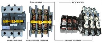
KMI contactor device
1. Base made of heat-resistant ABS plastic; 2. Fixed part of the magnetic system; 3. The moving part of the magnetic system; 4. Retractor coil; 5. Contact clamps; 6. Metal platform (for ratings over 25A); 7. Cross beam with movable bridge contacts; 8. Mounting screw; 9. Return spring; 10. Aluminum rings; 11. Fixed contact; 12. Connecting clamp with a notch for fixing external conductors.
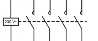
Connection diagrams for KMI contactors
Overall dimensions of contactors KMI-10910, KMI-10911, KMI-11210, KMI-11211, KMI-11810, KMI-11811, KMI-22510, KMI-22511
Overall dimensions of contactors KMI-23210, KMI-23211
Overall dimensions of contactors KMI-34010, KMI-34011, KMI-35012, KMI-46512
Overall dimensions of contactors KMI-48012, KMI-49512
The connection diagram for a magnetic starter (small-sized contactor “KM”) is not difficult for experienced electricians, but for beginners it can cause many difficulties. Therefore, this article is for them.
The purpose of the article is to show as simply and clearly as possible the very principle of operation (operation) of a magnetic starter (hereinafter referred to as MP) and a small-sized contactor (hereinafter referred to as KM). Go.
MP and KM are switching devices that control and distribute operating currents along the circuits connected to them.
MP and KM are mainly used for connecting and disconnecting asynchronous electric motors, as well as their reverse switching using remote control. They are used for remote control of lighting groups, heating circuits and other loads.
Compressors, pumps and air conditioners, heating furnaces, conveyor belts, lighting circuits are where and not only you can find MP and KM in their control systems.
What is the difference between a magnetic starter and a small-sized contactor, according to the principle of operation - nothing. Essentially, these are electromagnetic relays.
The difference found for a contactor - power - is determined by the dimensions, and for a starter - by the values, and the maximum power of the MP is greater than that of the contactor.
Visual diagrams of MP and CM
Conventionally, MP (or CM) can be divided into two parts.
In one part there are power contacts that do their job, and in the other part there is an electromagnetic coil that turns these contacts on and off.
- In the first part there are power contacts (movable on the dielectric traverse and stationary on the dielectric body), they then connect the power lines.
MP scheme
- MP power contacts
- Coil, return spring, additional MP contacts
- Push-button station (start and stop buttons)
Schematic diagram of MP connection
Scheme of linking the main elements of the circuit diagram with MP
As can be seen from Figure 5 with the diagram, the MP also includes additional block contacts, which are normally open and normally closed; they can be used to control the supply of voltage to the coil, as well as for other actions. For example, turn on (or turn off) a signal indication circuit that will show the operating mode of the MP as a whole.
Connection diagram in fact with connection of contact groups to the circuit diagram of the MP
Rice. 6 Enlarge fig. 6 Phase connection (220 V; zero - phase)
In the diagram (Fig. 6), through jumpers, we take the voltage supplied to the power contacts of the MP for its further use in controlling the coil through a push-button station.
This push-button post has two keys: “Start” (the contacts of which are normally open) and the “Stop” keys (the contacts of which are normally closed).
When you press the “Start” button, the power goes to the coil directly, and it is triggered, attracting the armature with the traverse on which the power contacts are located, the power contact circuits are closed.
It also closes the additional block contact to which the coil is connected.
On the other side of the additional contact there is a wire connected to the contact of the Stop button (the contacts of which are normally closed).
After the “Start” button returns to its original position (normally open), voltage ceases to be supplied to the coil through it, but it (the same voltage) begins to be duplicated through a closed additional contact and a wire connected to it, which is connected to the “Stop” button.
And only after pressing the “Stop” button, the circuit with the supply voltage to the MP coil is broken and completely de-energizes the coil. As a result, its electromagnetic field disappears, the armature ceases to be held and, under the influence of the return spring, opens the power contacts, as well as the additional (normally open) contact.
How does it work
The power unit spring keeps the contacts open. When the force from the armature becomes sufficient to overcome the elastic forces of the spring, the power and switching units begin to move. The anchor deforms the spring, simultaneously dragging the contacts along with it, and they close. The armature is in contact with the core of the coil and is held by its electromagnetic field. After de-energizing the coil, the spring returns to its original state along with the armature and contacts.
For normal operation of the contactor, a voltage of a strictly defined value is supplied to the terminals of its coil. For contactors used in electrical networks, these are 220 and 380 V. Therefore, it is necessary to correctly connect the coil to a three-phase network. If the rated voltage of the contactor is 220 V, the coil is connected to any of the phases (to phase voltage). And if 380 V - between any two phases (to line voltage).
A push-button station is used to control the contactor. It consists of two buttons:
- normally open for switching on;
- normally closed to turn off.
The contactor connection diagram combines an additional contact and a push-button station. The button designed to turn on and the additional contact are connected in parallel, and through them voltage is supplied to the coil. Pressing the power button closes the coil circuit. The anchor moves and closes all contacts. The additional contact makes the power button unnecessary to power the coil. Therefore, after the contactor has tripped, it can be released.
The state of the contactor will not change. It will remain on. But the contacts of the shutdown button are closed until the button is pressed. We press on it - the coil's power circuit is broken. The magnetic field disappears, and the contacts open under the influence of the contactor spring. The coil's power supply circuit is also broken at an additional contact. Therefore, the shutdown button can be released, and this will not affect the state of the contactor in any way.
KM scheme
- MP power contacts
- Coil, return spring, additional MP contacts
- Push-button station (start and stop buttons)
Schematic diagram of KM connection
Scheme for linking the main elements of the circuit diagram with the CM
Connection diagram in fact with connection of contact groups to the circuit diagram of the CM
Rice. 10 Enlarge fig. 10 Phase connection (220 V; zero - phase)
The principle of operation of the CM and its coil (in this diagram, Fig. 10) is similar to that described above. One of the design differences is that the additional contact is located on the traverse in the same row as the power contacts.
Please note that the coil voltage in the diagrams is 220 and 380 volts. This means that the coils must be connected according to their rated voltage.
Phase connection (phase, neutral - simpler zero) corresponds to 220 V, linear connection (phase, phase) 380 V.
There are also 12, 24, 36, 42, 110 volt coils, so before you apply voltage to the coil, you must know exactly its rated operating voltage.
Visual electrical diagrams for connecting an electric motor using a magnetic starter (or small-sized contactor)
additional information
There is no fundamental difference between a contactor and a magnetic starter, and this has already been mentioned above. Their task is also the same - remotely turning on and off the load. The circuits in which these types of switches are used are also identical. When describing circuits, some specific terms are used. We will dwell on them further for completeness of information.
"Self-pickup." This means that the power button in the push-button station is connected in parallel with a contact that is closed by the action of the coil, the power of which begins immediately when the said button is pressed. Self-retaining, although not mentioned earlier, is present in each of the schemes shown above.
"Reverse". The reverse circuit involves obtaining from two contactors or magnetic starters the switching of the motor windings to change the rotation of its rotor to the opposite. An example of such a scheme is given below.
Read also: How to make wood engraving
The connection diagram for a magnetic starter (small-sized contactor “KM”) is not difficult for experienced electricians, but for beginners it can cause many difficulties. Therefore, this article is for them.
The purpose of the article is to show as simply and clearly as possible the very principle of operation (operation) of a magnetic starter (hereinafter referred to as MP) and a small-sized contactor (hereinafter referred to as KM). Go.
MP and KM are switching devices that control and distribute operating currents along the circuits connected to them.
MP and KM are mainly used for connecting and disconnecting asynchronous electric motors, as well as their reverse switching using remote control. They are used for remote control of lighting groups, heating circuits and other loads.
Compressors, pumps and air conditioners, heating furnaces, conveyor belts, lighting circuits are where and not only you can find MP and KM in their control systems.
What is the difference between a magnetic starter and a small-sized contactor, according to the principle of operation - nothing. Essentially, these are electromagnetic relays.
The difference found for a contactor - power - is determined by the dimensions, and for a starter - by the values, and the maximum power of the MP is greater than that of the contactor.
Connection diagrams for MP (or KM) with a 220 V coil
- “STOP” button – “Stop” button
- “START” button – “Start” button
- KMP – coil MP (magnetic starter)
- Kn MP – power contacts MP
- BC – block contact MP
- Tr – heating element of thermal relay
- KTR – thermal relay contact
- M – electric motor
Electric motor connection diagram (recommended type of connection of windings is triangle) for 220 V
The designation of elements is similar to cx. Higher
Please note that the circuit involves a thermal relay, which, through its additional contact (normally closed), duplicates the function of the “Stop” button in the push-button station.
Principle of operation
The principle of operation of a magnetic starter actually coincides with a relay. To operate the starter from pushbuttons without latching, self-locking from contacts parallel to the button is used. To turn off, a normally closed button is used, connected in series to the control circuit. When the contacts open, the starter turns off and is ready to be turned on again immediately after the contacts of the stop button are closed.
The “push-button” version of starter control is overwhelming for manual operations. In automation circuits, starters are usually kept in the on state by a continuous signal supplied from the discrete output of the controller to the intermediate relay.
There are different types of starters, among which there are reversible magnetic starters (a “headache” for novice electricians who are trying to understand how an unusual circuit works and are not used to thinking in electrical circuits). In fact, these are two starters operating strictly alternately: if one is turned on, then the other must be turned off, otherwise there will be a short circuit between the phases.
Its principle is as follows: if in one switched-on position the sequence of phases is A, B, C, then in another position there should be, for example, A, C, B, that is, two phases should swap places. This allows you to change the direction of the rotating field in asynchronous motors and run them in different directions, either clockwise or counterclockwise.
The principle of operation of a magnetic starter and a small-sized contactor + Video explanation
»
Important: for clarity, in the diagrams the magnetic starter is shown without an arc-extinguishing cover, without which its operation is prohibited!
Sometimes the question arises: why use MP or KM at all, why not just use a three-pole machine?
- The machine is designed for up to 10 thousand shutdowns and starts, and for MP and KM this figure is measured in millions
- During power surges, the MP (KM) will turn off the line, playing the role of protection
- The machine cannot be controlled by remotely applying a small voltage
- The machine will not be able to perform additional functions of turning on and off additional circuits (for example, signal circuits) due to the lack of additional contacts
In a word, the machine perfectly copes with its main function of protection against short circuits and overvoltages, and MP and PM do theirs.
KMI series contactors
Regulatory and technical documentation
In terms of their design and technical characteristics, contactors of the KMI series meet the requirements of Russian and international standards GOST R 50030.4.1,2002, IEC60947,4,1,2000 and have a certificate of conformity ROSS CN.ME86.B00144. According to the All-Russian Product Classification, contactors of the KMI series are assigned code 342600.
terms of Use
Application categories: AC,1, AC,3, AC,4. Ambient temperature – during operation: from –25 to +50 °C (lower limit temperature –40 °C); – during storage: from –45 to +50 °C. Altitude above sea level, no more than: 3000 m. Working position: vertical, with a deviation of ±30°. Type of climatic modification according to GOST 15150.96: UHL4. Degree of protection according to GOST 14254.96: IP20.
Designation structure
When selecting KMI contactors, pay attention to the structure of the symbol
Main technical characteristics
Power Circuit Specifications
Control Circuit Specifications
Connecting the power circuit
Control circuit connection
| Options | Values |
| Flexible cable, mm2 | 1—4 |
| Rigid cable, mm2 | 1—4 |
| Torque when tightening, Nm | 1,2 |
Technical characteristics of built-in auxiliary contacts
| Options | Values | |
| Rated voltage Ue, V | AC current | up to 660 |
| fast. current | ||
| Rated insulation voltage Ui, V | 660 | |
| Thermal resistance current (t°≤40°) Ith , A | 10 | |
| Minimum making capacity | Umin, V | 24 |
| Imin, mA | 10 | |
| Overcurrent protection - fuse gG, A | 10 | |
| Maximum short-term load (t ≤1 s), A | 100 | |
| Insulation resistance, not less, MOhm | 10 | |
Electrical circuits
Typical electrical circuits
Contactors of the KMI series can be used to create standard electrical circuits.
Reversing electrical circuit
This circuit is assembled from two contactors and a locking mechanism MB 09.32 or MB 40.95 (depending on the type), designed to prevent the simultaneous activation of contactors.
Electrical circuit "star-delta"
This starting method is intended for motors whose rated voltage corresponds to the delta connection of the windings. Star-delta starting can be used for motors starting without load or with reduced load torque (no more than 50% of the rated torque). In this case, the starting current when connected to a “star” will be 1.8–2.6 A of the rated current. Switching from star to delta must be done after the engine reaches its rated speed.
Design and installation features
Connecting clamps ensure reliable fixation of conductors: – for sizes 1 and 2 – with hardened disc washers; – for sizes 3 and 4 – with a clamping bracket that allows you to connect a contact with a larger cross-section.
There are two ways to install contactors:
- Quick installation on DIN rail:
KMI from 9 to 32 A (dimensions 1 and 2) – 35 mm; KMI from 40 to 95 A (dimensions 3 and 4) – 35 and 75 mm.
- Installation with screws.
KMI series contactors of 3rd and 4th dimensions allow mounting on a 75 mm DIN rail.
KMI series contactors of the 3rd and 4th dimensions are equipped with a hole for a grounding bolt.
dimensions
| Type version | Size, mm | ||
| IN | WITH | D | |
| KMI 10910. KMI 10911 | 74 | 79 | 45 |
| KMI 11210, KMI 11211 | 74 | 81 | 45 |
| KMI 11810, KMI 11811 | 74 | 81 | 45 |
| KMI 22510, KMI 22511 | 74 | 93 | 55 |
KMI 23210, KMI 23211
KMI 34010, MI 34011, KMI 35012, KMI 46512
KMI 48012, KMI 49512
Installation dimensions
Overall and installation dimensions of KMI contactors when mounted on a 35 mm DIN rail
| Type version | Size, mm | ||
| WITH | B | D | |
| KMI 10910, KMI 10911 | 82 | 74 | 45 |
| KMI 11210, KMI 11211 | 82 | 74 | 45 |
| KMI 11810, KMI 11811 | 87 | 74 | 45 |
| KMI 22510, KMI 22511 | 95 | 74 | 55 |
| KMI 23210, KMI 23211 | 100 | 83 | 55 |
Type Size, mmSDKMI 34010, KMI 3401113174KMI 3501213174KMI 4651213174KMI 4801214284KMI 4951214284
Overall and installation dimensions of KMI contactors when installed on a mounting panel or mounting profile
KMI contactors are used to start, stop and reverse asynchronous electric motors operating at voltages up to 660 volts. In addition, these devices provide remote switching of ventilation system devices, lighting fixtures, pumps and other units. The use of contactors of this type makes controlling electric motors convenient and safe.
Range.
| Name | Rated operating current, A | Rated voltage of control coils, V | Number and type of contacts | Quantity, pcs | vendor code | ||
| packaged | in a transport box | ||||||
| KMI-10910 9A 24V/AS-3 1NO IEK | 9 | 24 | 1z | 1 | 50 | KKM11-009-024-10 | |
| KMI-10910 9A 36V/AS-3 1NO IEK | 9 | 36 | 1z | 1 | 50 | KKM11-009-036-10 | |
| KMI-10910 9A 110V/AS-3 1NO IEK | 9 | 110 | 1z | 1 | 50 | KKM11-009-110-10 | |
| KMI-10910 9A 230V/AS-3 1NO IEK | 9 | 230 | 1z | 1 | 50 | KKM11-009-230-10 | |
| KMI-10910 9A 400V/AS-3 1NO IEK | 9 | 400 | 1z | 1 | 50 | KKM11-009-400-10 | |
| KMI-10911 9A 110V/AS-3 1NZ IEK | 9 | 110 | 1r | 1 | 50 | KKM11-009-110-01 | |
| KMI-10911 9A 230V/AS-3 1NZ IEK | 9 | 230 | 1r | 1 | 50 | KKM11-009-230-01 | |
| KMI-10911 9A 400V/AS-3 1NZ IEK | 9 | 400 | 1r | 1 | 50 | KKM11-009-400-01 | |
| KMI-11210 12A 24V/AS-3 1NO IEK | 12 | 24 | 1z | 1 | 50 | KKM11-012-024-10 | |
| KMI-11210 12A 36V/AS-3 1NO IEK | 12 | 36 | 1z | 1 | 50 | KKM11-012-036-10 | |
| KMI-11210 12A 110V/AS-3 1NO IEK | 12 | 110 | 1z | 1 | 50 | KKM11-012-110-10 | |
| KMI-11210 12A 230V/AS-3 1NO IEK | 12 | 230 | 1z | 1 | 50 | KKM11-012-230-10 | |
| KMI-11210 12A 400V/AS-3 1NO IEK | 12 | 400 | 1z | 1 | 50 | KKM11-012-400-10 | |
| KMI-11211 12A 110V/AS-3 1NZ IEK | 12 | 110 | 1r | 1 | 50 | KKM11-012-110-01 | |
| KMI-11211 12A 230V/AS-3 1НЗ IEK | 12 | 230 | 1r | 1 | 50 | KKM11-012-230-01 | |
| KMI-11211 12A 400V/AS-3 1NZ IEK | 12 | 400 | 1r | 1 | 50 | KKM11-012-400-01 | |
| KMI-11810 18A 24V/AS-3 1NO IEK | 18 | 24 | 1z | 1 | 50 | KKM11-018-024-10 | |
| KMI-11810 18A 36V/AS-3 1NO IEK | 18 | 36 | 1z | 1 | 50 | KKM11-018-036-10 | |
| KMI-11810 18A 110V/AS-3 1NO IEK | 18 | 110 | 1z | 1 | 50 | KKM11-018-110-10 | |
| KMI-11810 18A 230V/AS-3 1NO IEK | 18 | 230 | 1z | 1 | 50 | KKM11-018-230-10 | |
| KMI-11810 18A 400V/AS-3 1NO IEK | 18 | 400 | 1z | 1 | 50 | KKM11-018-400-10 | |
| KMI-11811 18A 230V/AS-3 1NZ IEK | 18 | 230 | 1r | 1 | 50 | KKM11-018-230-01 | |
| KMI-11811 18A 110V/AS-3 1NZ IEK | 18 | 110 | 1r | 1 | 50 | KKM11-018-110-01 | |
| KMI-11811 18A 400V/AS-3 1NZ IEK | 18 | 400 | 1r | 1 | 50 | KKM11-018-400-01 | |
| KMI-22510 25A 24V/AS-3 1NO IEK | 25 | 24 | 1z | 1 | 50 | KKM21-025-024-10 | |
| KMI-22510 25A 36V/AS-3 1NO IEK | 25 | 36 | 1z | 1 | 50 | KKM21-025-036-10 | |
| KMI-22510 25A 110V/AS-3 1NO IEK | 25 | 110 | 1z | 1 | 50 | KKM21-025-110-10 | |
| KMI-22510 25A 230V/AS-3 1NO IEK | 25 | 230 | 1z | 1 | 50 | KKM21-025-230-10 | |
| KMI-22510 25A 400V/AS-3 1NO IEK | 25 | 400 | 1z | 1 | 50 | KKM21-025-400-10 | |
| KMI-22511 25A 110V/AS-3 1NZ IEK | 25 | 110 | 1r | 1 | 50 | KKM21-025-110-01 | |
| KMI-22511 25A 230V/AS-3 1NZ IEK | 25 | 230 | 1r | 1 | 50 | KKM21-025-230-01 | |
| KMI-22511 25A 400V/AS-3 1NZ IEK | 25 | 400 | 1r | 1 | 50 | KKM21-025-400-01 | |
| KMI-23210 32A 36V/AS-3 1NO IEK | 32 | 36 | 1z | 1 | 50 | KKM21-032-036-10 | |
| KMI-23210 32A 110V/AS-3 1NO IEK | 32 | 110 | 1z | 1 | 50 | KKM21-032-110-10 | |
| KMI-23210 32A 230V/AS-3 1NO IEK | 32 | 230 | 1z | 1 | 50 | KKM21-032-230-10 | |
| KMI-23210 32A 400V/AS-3 1NO IEK | 32 | 400 | 1z | 1 | 50 | KKM21-032-400-10 | |
| KMI-23211 32A 110V/AS-3 1NZ IEK | 32 | 110 | 1r | 1 | 50 | KKM21-032-110-01 | |
| KMI-23211 32A 230V/AS-3 1NZ IEK | 32 | 230 | 1r | 1 | 50 | KKM21-032-230-01 | |
| KMI-23211 32A 400V/AS-3 1NZ IEK | 32 | 400 | 1r | 1 | 50 | KKM21-032-400-01 | |
| KMI-34012 40A 36V/AS-3 1NO;1NC IEK | 40 | 36 | 1z+1r | 1 | 20 | KKM31-040-036-11 | |
| KMI-34012 40A 110V/AS-3 1NO;1NC IEK | 40 | 110 | 1z+1r | 1 | 20 | KKM31-040-110-11 | |
| KMI-34012 40A 230V/AS-3 1NO;1NC IEK | 40 | 230 | 1z+1r | 1 | 20 | KKM31-040-230-11 | |
| KMI-34012 40A 400V/AS-3 1NO;1NC IEK | 40 | 400 | 1z+1r | 1 | 20 | KKM31-040-400-11 | |
| KMI-35012 50A 110V/AS-3 1NO;1NC IEK | 50 | 110 | 1z+1r | 1 | 20 | KKM31-050-110-11 | |
| KMI-35012 50A 230V/AS-3 1NO;1NC IEK | 50 | 230 | 1z+1r | 1 | 20 | KKM31-050-230-11 | |
| KMI-35012 50A 400V/AS-3 1NO;1NC IEK | 50 | 400 | 1z+1r | 1 | 20 | KKM31-050-400-11 | |
| KMI-46512 65A 110V/AS-3 1NO;1NC IEK | 65 | 110 | 1z+1r | 1 | 20 | KKM41-065-110-11 | |
| KMI-46512 65A 230V/AS-3 1NO;1NC IEK | 65 | 230 | 1z+1r | 1 | 20 | KKM41-065-230-11 | |
| KMI-46512 65A 400V/AS-3 1NO;1NC IEK | 65 | 400 | 1z+1r | 1 | 20 | KKM41-065-400-11 | |
| KMI-48012 80A 110V/AS-3 1NO;1NC IEK | 80 | 110 | 1z+1r | 1 | 16 | KKM41-080-110-11 | |
| KMI-48012 80A 230V/AS-3 1NO;1NC IEK | 80 | 230 | 1z+1r | 1 | 16 | KKM41-080-230-11 | |
| KMI-48012 80A 400V/AS-3 1NO;1NC IEK | 80 | 400 | 1z+1r | 1 | 16 | KKM41-080-400-11 | |
| KMI-49512 95A 110V/AS-3 1NO;1NC IEK | 95 | 110 | 1z+1r | 1 | 16 | KKM41-095-110-11 | |
| KMI-49512 95A 230V/AS-3 1NO;1NC IEK | 95 | 230 | 1z+1r | 1 | 16 | KKM41-095-230-11 | |
| KMI-49512 95A 400V/AS-3 1NO;1NC IEK | 95 | 400 | 1z+1r | 1 | 16 | KKM41-095-400-11 | |
Purpose and features of small-sized contactors
Frequent changes in current in electrical networks when turning electrical equipment on and off leads to emergency situations. To prevent them, a KMI contactor is used, which operates remotely under the control of weak electric currents. The name stands for small contactor. The device is also known as a KME contactor, that is, electromagnetic. It closes and opens electrical circuits that are in normal mode. These devices do not protect against short circuits, like automatic machines, but only carry out a combination of rated currents on different lines.
The small-sized KMI contactor is designed for a current load in the range of 9-95 A. Basically, these are asynchronous electric motors with a squirrel-cage rotor, as well as various types of loads with low inductance. Devices operating with a current load of up to 40 A are equipped with one group of make-break contacts. For currents above 40 A, two separate contact groups are installed - making and breaking.
These devices switch three-phase capacitor banks, as well as primary windings in three-phase low-voltage transformers. Exactly the same functions are performed by the small-sized KME - electromagnetic contactor.
Equipment of this type has undoubted advantages:
- The KMI - IEK series is produced in a wide range, significantly exceeding the number of analogues on the domestic market of electrical appliances.
- Together with contactors there are a large number of additional devices - contact attachments, electrothermal relays, time delay attachments and other useful equipment. They protect the electric motor from maximum current overloads, phase distortions and asymmetry, prolonged starting and rotor jamming.
- All KMI - IEK devices can be freely installed on a DIN rail with a width of 35 mm, unlike domestic products, for which such fasteners are installed only upon request.
- KMI-IEK devices allow reverse operation using a special locking mechanism.
- The design of the cover allows you to install additional contacts using a special attachment.
Basic device
The contactor consists of several units:
- Energy.
- Powerful.
- Switching.
The energy node ensures the formation of an electromagnetic field sufficient to obtain a certain unidirectional force. This field appears as a consequence of the flow of electric current through a coil with a core. Its shape is either U- or W-shaped, depending on the design of this switching product.
The magnetic field lines are most concentrated near the core, and therefore the power unit is designed so that the impact on it from the energy unit is maximized. For a more uniform force that occurs when alternating current flows through the coil, a short-circuited turn is made in it. It plays the role of a damper that prevents contact chatter at a frequency of 50 Hz. If the coil is powered by direct current, a dielectric spacer is placed on its core to prevent magnetized parts from sticking together.
The power unit contains a movable spring-loaded ferromagnetic element - an armature, which is attracted to the stationary coil core, transmitting force to the switching unit. It contains contacts. Their number may vary, depending on the design of the contactor. To control electric motors in three-phase networks, there are three or four contacts - identical in their characteristics. But there may also be additional low-power contacts used to control auxiliary elements of the circuit.
- The location of additional contacts determines the difference between a contactor and a magnetic starter. They are located in a group with the main contacts, and not on the side, as in a magnetic starter.
In addition to the contacts, the switching block contains chambers for extinguishing the electric arc.
Structural elements
Each KMI contactor is equipped with a coil or electromagnet, which forms the basis of the device. This component is powered over a wide voltage range - 12-380 volts. Before connecting, you need to accurately set the operating current of the electromagnet, indicated in the passport or on the side of the coil body.
The next important design element is the core. It is a prefabricated structure with metal plates impregnated with varnish. The core consists of fixed and moving parts. The first part is used to accommodate the coil, and the other part - the movable one - is intended to accommodate the movable contacts. The fixed contacts are secured using screws to the plastic body of the device. Movable – attached to the core with a special insulating holder. Short-circuited aluminum rings are pressed into the pole tips of the stationary part, eliminating the effect of detonation.
The contact area of the contact solders in different IEC designs may differ. It depends on the operating current of the power circuits, which can be passed by the contactor. In this regard, each type of device has its own value - first, second, third, etc. Most of them are equipped with four contact pairs: three are intended for the power circuit, and one is additional and performs various functions. It blocks the control circuit, turns on a sound or color alarm, and partially provides automatic relay protection for the control of electrical installations.
The conductors are connected using special connecting contacts. They have an oval shape, which increases the reliability of fixation. For small wires, hardened disc washers are used, and for large conductors, a clamping clamp is provided. Notches on the contacts further increase the reliability of fixation, increase the contact area and reduce heating of the wires.
When power is applied to the coil, it results in an electromagnetic effect. Under its influence, the metal cylinder begins to move upward, after which the contact closes. The circuit supplying power to the coil is considered the control circuit, and the voltage in it is quite low, within 24 volts. The other circuit that closes the contact is a power circuit, since a current with a voltage of up to 660 volts passes through it. In the absence of power supply, the metal core returns to its original position under the action of a spring, and the circuit is open.
Technical characteristics and types of KMI
The standard KMI contactor is an alternating current electromagnetic device that provides switching of electrical installations and equipment with power circuits.
Each model has the symbol KMI-Х-ХХ-Х-Х, which is deciphered as follows:
- The first character X means operating current limits, which are 1-9, 12, 12 A, 2-25, 32 A, 3-40, 50 A, 4-65, 80, 95 A and correspond to specific groups of devices.
- The second symbol XX corresponds to the rated current of category AC-3 and means several groups of small-sized starters. 1st group - 9, 12 and 18 A, 2nd group - 25 and 32 A, 3rd group - 40 and 50 A, 4th group - 65, 80 and 95 A.
- The third character X indicates the specific configuration of the contactor. For example, the number 1 corresponds to a device without a shell and without reverse.
- The fourth X character indicates the number of additional contacts. The number 0 is 1 normally open contact, the number 1 is 1 normally closed contact. The number 2 corresponds to the 1st make and 1st break contact.
The main parameters and technical characteristics include the following:
- The rated operating voltage is 230, 400 and 660 volts.
- The rated insulation voltage is 660 V.
- The rated pulse voltage is 6 kV.
- Rated operating current – 9-95 A.
- The value of the conventional thermal current is from 25 to 125 A.
- Indicators of maximum short-term load for less than 1 s for different devices range from 162 to 1710 A.
There are other device characteristics specified in the technical documentation that should be taken into account when choosing a product.
The manufacturer IEK produces a wide range of devices with different parameters and the possibility of use in various electrical circuits. Among them, three main groups can be noted:
- Small-sized AC IEC devices 9-95 A. Used for remote control of various industrial electrical installations, in lighting systems, etc.
- The contactor is a small-sized KMI with a thermal lever in its design. It is placed in a metal or plastic case and is used for switching three-phase motors operating with voltages up to 400 volts. If any phase is broken and overloads occur, this device is triggered and protects the circuit.
- KMI contactor, which has a coil that controls direct current. Used in automatic transfer systems, at power plants and distribution points, in electrical networks of railways and subways. There is no inrush operating current in the control coil.