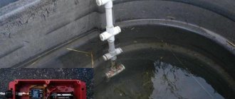
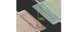
For testing and subsequent use, a cheap Chinese sensor was selected, which uses optical technology of a combination of a single infrared emitter and receiver to achieve non-contact determination of liquid level. The sensor itself has no electronic interface circuitry - it simply contains one infrared LED and one phototransistor inside.
Optical level sensor design
It can be installed in any direction and installation can only take a few minutes as there is no calibration procedure. It is recommended to install the sensor on the side or bottom of the liquid reservoir for best results. Please note that performance will be adversely affected by other reflective surfaces in the immediate vicinity of the sensor head.
Hardware overview
This sensor contains a series of ten open copper traces, five of which are power and five are sensitive.
These tracks are interleaved so that between every two supply tracks there is one sensing track.
Usually these paths are not connected to each other, but when immersed they are connected by water.
Figure 1 – Water level sensor
There is a power indicator on the board that lights up when power is applied to the board.
Electrical diagram for connecting the module
Typical electrical circuit for operation from a 5 V power supply.
The cable protrudes from the sealed sensor assembly and has a small 4-pin (2-pair) wire connector at the end. One pair of these wires is connected to the LED (light emitter) inside, and the other is connected to the phototransistor (light receiver). Here is a typical connection diagram for an optical liquid level sensor.
Although the diagram above gives a general idea of the connections, we recommend checking the color code of the wires before testing, as incorrect connections may damage the electronics.
Materials and tools
As in the manufacture of his other “crafts,” the assembly of the indicator was almost entirely carried out using radio components and other necessary elements that were already in use. To independently manufacture such a system, I used parts in the following quantities:
- Three-pin reed switch: 2 pcs.
- Low power LEDs: 3 pcs. (red, yellow and green).
- Plastic clamps: 2 pcs.
- Neodymium magnet.
- Heat-shrinkable cambric 40 mm.
- Low voltage five-core wire.
- Connecting sleeve 50 mm: 2 pcs.
- Rivets: 10 pcs.
- Plugs 50 mm: 2 pcs.
- Furniture profiles made of plastic.
- Resistor 680 Ohm.
- Four-pin plug.
- Switch button.
I used a 3.7 volt battery as a power source, but you can also use two AA batteries connected in series.
Source hobmodels.ru
Soldering batteries can lead to boiling of the electrolyte and rupture of the case, therefore, when using 1.5 V products, it is recommended to purchase and install a special box to which contact wires can be soldered without problems.
Do-it-yourself assembly of the water level indicator in the tank was carried out using the following tools:
- Soldering iron.
- Drills.
- Construction hair dryer.
- Thermal gun.
Also, when installing the alarm system, you cannot do without a screwdriver and pliers.
Operating principle of an optical level sensor
The sensor contains an infrared LED and a phototransistor. Because the light from the LED is transmitted to the optical head, the phototransistor receives zero light (or less light) when the sensor is immersed in the liquid - the passing light beam will be refracted. If there is no liquid, the transmitted light will be returned to the phototransistor directly through the optical head. Therefore, if the sensor detects the liquid level, it issues a low level signal.
Useful: Homemade powerful 100-watt wireless speaker
The figure below shows several options for installing the sensor in various containers.
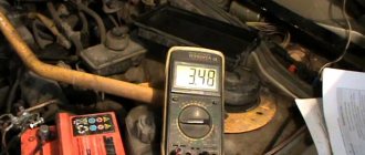
By looking at the output signal with a multimeter, you can see a logic high signal in the "dry state" and a logic low signal in the "wet state". The following circuit allows you to use the sensor output to directly control an indicator or even a standard electromagnetic relay.
Here you may need to change the value of R1 (minimum 390 ohms) and R2 (maximum 10 kohms) to get acceptable results. The BS170 element (T1) is a small signal N-channel, 500 mA, 60 V MOSFET available in a TO-92 package, but not logic level.
Time diagrams of operation in filling and pumping modes
Depending on the selected operating mode, two diagrams are possible.
Diagram when working to fill a container:
Diagram of operation of the level switch in filling mode
The curve in the diagram is the liquid level, Max and Min are the levels at which the sensors are installed. Graph K shows the operation of the output relay (in fact, the operation of the pump). Graphs R and K are almost the same, with the exception of the delay time indication. Graph L shows the achievement and loss of the desired level, and if you do not take into account the delay indication, it is the inverse of graph R.
In pumping mode, the schedule will be like this:
Diagram of operation in drainage (pumping) mode
Taking a closer look at both graphs, you will notice that they are very similar. And if it were not for the delay times (and there is no way without them!), it would be possible to use one mode for all applications, simply by switching the relay terminal from normally open to normally closed. In the level control machine, the transition from mode to mode is implemented differently, more on that below.
I have doubts about the delay time Tz - in all cases it should be the same, although this is not the case in the graphs. Well, when installing and studying this level controller in practice, we will clarify this point.
Level meter circuit upgrade
This time it's all based on the popular CD4049UB hexadecimal inverting buffer and converter (IC1). The chip has standardized symmetrical output characteristics, a wide operating voltage range from 3 V to 18 V and is recommended for devices that do not require high current or voltage conversion.
Here, the CD4049UB-based circuit provides single-point liquid level sensing via a TTL-compatible push-pull output, but more optical level sensors can be added to implement your own expandable, multi-channel, microcontroller-compatible liquid level sensing module.
Waterproof Ultrasonic Sensor JSN SR-04T
JSN SR-04T is a waterproof ultrasonic sensor module that is capable of measuring distance at distances of 25-450cm with an accuracy of 2mm. The sensor module consists of two separate parts. One part is a sensor that directly transmits and receives ultrasonic waves, and the second part is a control board. The operating principle of the JSN SR-04T is very similar to parking sensors that are installed in car bumpers.
The JSN SR-04T sensor module has a waterproof sensor design, features stable operation in difficult operating conditions and high accuracy of distance measurement. It can be used in ranging, obstacle avoidance, automated control, object movement monitoring, traffic control, security and artificial intelligence systems and many other applications.
The assignment of contacts (pinout) of the JSN SR-04T sensor is presented in the following figure and table.
| Contact no. | Contact name | Contact assignment |
| 1 | 5V | Supply voltage |
| 2 | Trig | Sensor input contact. It is necessary to apply a pulse with a duration of 10 μs to start the sensor into operation (so that it starts emitting an ultrasonic wave). |
| 3 | Echo | Sensor output contact. After receiving an ultrasonic wave reflected from an obstacle, a high-level pulse (high) is formed at this contact, the duration of which is equal to the time of propagation of the ultrasonic wave to the obstacle and back. |
| 4 | Gnd | Common wire (ground) |
The JSN SR-04T sensor module is similar in many ways to the ultrasonic sensor module, but it has a number of advantages over it:
- Unlike the HC-SR04, the JSN SR-04T module does not have the sensor directly soldered on the module’s printed circuit board; instead, it is attached to the end of a fairly long cable (2.5 meters), so the sensitive element of the sensor can be removed a considerable distance from the control board ;
- The sensitive element of the sensor is enclosed in a protected waterproof housing, so it can be placed in harsh operating conditions and aggressive environments.
But despite these advantages, there are also some disadvantages. For example, the minimum measuring distance of the JSN SR-04T sensor is 20 cm, while the minimum measuring distance of the HC-SR04 sensor is 2 cm. The reason for this is that the JSN SR-04T has only one sensing element while The HC-SR04 sensor has two of them - one is used to transmit ultrasonic waves, and the other is used to receive. As a result, the sensitive element of the JSN SR-04T sensor has to switch between two modes (reception/transmission), and this requires additional time. Therefore, the minimum measuring distance for the JSN SR-04T sensor is 20 cm, and the HC-SR04 sensor can measure significantly shorter distances due to the presence of a separate transmitter and receiver.
Main technical characteristics and features of the JSN SR-04T sensor:
- Operating voltage: DC 5V (direct current);
- current at rest (standby): 5mA;
- operating current: 30mA;
- ultrasonic wave frequency: 40 kHz;
- distance measurement range: from 25 cm to 4.5 m;
- cable length: 2.5 meters.
Test results and real work
Testing has found that there are no false alarms, even when installed inside a small transparent water tank in bright daylight. If you immerse the tip of the sensor (the clear prism) in water, it works as expected.
In general, this optical level sensor has no moving parts and is ideal for measuring extreme water levels. It produces an output signal that can indicate the presence or absence of liquid. A compact and inexpensive optical liquid level sensor like this is a good choice, especially where measurement accuracy is not important.
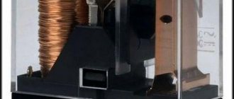
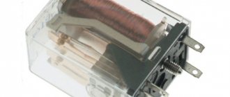
Liquid level relay
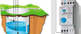
As the name of the device suggests, level control relays are designed to regulate and maintain a given liquid level in a tank. Receiving a signal from level control sensors located in the tank itself, the relay controls the operation of actuators - pump electric motors, solenoid valves, etc.
With its help, you can operate pumps in automatic mode, protect the pump from dry running, control fluid leakage, and find various applications in automation and protection circuits.
The relay operates by measuring the fluid resistance between the common electrode and the upper and lower level electrodes. It can be used in electrically conductive liquids such as tap water, spring water, rain water, sea water, low alcohol liquids, milk, beer, coffee, waste water. Distilled water, gasoline, oil, liquefied gas, kerosene, and ethylene glycol are not suitable for relay operation.
The essence of the operation of the control relay when filling the tank is as follows - if the liquid level drops below the set mark, then the relay, receiving a signal from the minimum level sensor located at the lower mark, turns on the pump and the tank is filled with water again. When the water reaches the upper level, the maximum level sensor signals this relay and then, in turn, sends a command to stop the pump. This way the storage tank never remains empty.
In the same way, you can do the opposite for draining, for example, a basement or cellar, when when the maximum level is reached, the relay will give a command to pump out the water, and when it drops below the minimum, turn off the pump.
Most relays have a time delay function when switching, which increases the service life of the pumps.
Since the switched currents of the relay output circuits are usually small, to control powerful loads in the circuit it is necessary to use a contactor. The level control relay will control the contactor coil, and the contactor itself will directly control the load.
The control relay can be controlled by two or three level sensors. They are usually not included in the kit, so you will have to buy them separately. Electrode and float type sensors are usually used.
The electrode sensor consists of three electrodes - one short and two long. The short electrode acts as a maximum level sensor, and the long ones serve as a minimum level sensor. When the liquid comes into contact with the short electrode, the pump motor turns off, signaling that the upper level has been reached. When the liquid level drops to the long electrodes, the pump turns on and the container begins to fill.
The float sensor is based on a float with a magnet installed inside it and a reed switch built into the sensor tube. When the liquid level changes, the float rises or falls, the magnet approaches the reed switch, which leads to the closure of the contact.
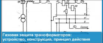
Wiring diagram for level relay EKF RL-SA
The operation of the relay is based on measuring the resistance of conductive liquids between the common contact “C” and the contacts of the maximum “MAX” and minimum “MIN” levels. When the upper level is reached, the relay turns off, the contacts switch to position 11 - 12. The relay remains in the off state until the liquid level drops below the minimum, then the relay turns on, the contacts switch to position 11 - 14.