When planning energy supply at a facility, one of the important issues is saving materials. Laying a separate power line from the circuit breaker to each consumer is irrational, so nodal points and branching wires are made on the power main. Each additional connection requires the installation of a junction box.
Purpose of distribution boxes
Electrical wiring must be divided into groups depending on the energy consumer. For this purpose, similar structures are installed that perform important tasks:
- ensuring fire safety;
- aesthetics.
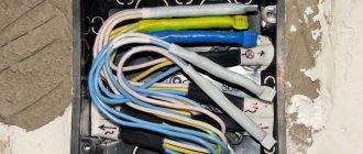
Under the body of the box there are conductors, which are thus protected from various damages. This allows you to increase the service life of electrical wiring.
Junction box with conductors
The main task of the distribution box
With this design, you can reduce the budget for organizing electrical wiring. After all, in the absence of a distribution box, a cable would have to be connected to each electrical appliance, which would create too many channels that would have to be hidden in the ceiling. In addition, all this does not look aesthetically pleasing.
At the same time, the correct distribution of conductors inside the box increases the level of fire safety in any type of room. This is due to the insulation of connections and flammable materials that are located in the wall. In addition, this design is convenient for repair work.
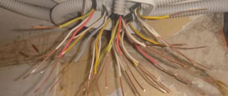
However, the main function of the distribution box is to distribute electricity between consumers that are installed in a specific room. In addition, the design of the product allows for expansion by adding additional branches (when it is necessary to install a new switch or socket).
You can add a branch to the distribution box for a new energy consumer
Types of distribution boxes
Based on the body material, boxes are divided into:
- Metal - for installation in rooms built from flammable materials (wood, plastic), or on walls insulated with flammable material. They may have a dielectric layer inside to reduce the likelihood of unauthorized contact closure.
- Plastic are the most common due to their low manufacturing cost. They are made either from non-flammable material, for use in conditions of high fire danger, or from materials that do not support combustion. That is, the junction box in any design should not become a source of fire, even if the wiring ignites inside.
According to installation conditions:
- For indoor installation. Designed for installation in walls and cladding. They consist of a body, which must be firmly held in the supporting structure, and a flat cover. In turn, the cover must be removable for access to the contact group or twists. In such boxes, the thickness of the case can be thinner, because it does not bear the structural load.
- As a rule, built-in boxes are made in a round shape. When installing into a monolithic wall, drilling an installation hole using a crown is much easier. For installation in drywall, you can use rectangular (square) housings. It is easy to cut such a hole in the gypsum board. From the point of view of connecting wires, it is more convenient to work with a square (rectangular) case.
- For outdoor installation (non-sealed) - conditions of use - indoors or closed cabinets. The housing is both protection from the external environment and a strength element of the structure. Therefore, it must be thicker and stronger. Distribution box6 To prevent foreign objects from getting inside, the outer boxes are equipped with sealing clamps for wires.
- For outdoor installation (sealed). Installation of the distribution box outdoors involves direct exposure to water, frost, and fog. Since water is a conductor, the inside of the housing must be dry. Therefore, sealed boxes have a rubber seal along the sealing contour of the lid, and crimp (collet) clamps for inserting wires.
- Of course, additional equipment of products (moisture protection, etc.) increases the cost. Therefore, when choosing a package, we usually proceed from the principle of reasonable sufficiency.
Junction boxes can be equipped with a ready-made set of connectors for wires. Or you buy an empty case, and the fittings are selected separately.
Why does the box have different names?
This piece of electrical equipment goes by several names, including: distribution box, branch box, junction box. Only their operating principle is the same: the box is a center where electricity is supplied from the power source, and then it is distributed through separate channels that go to switches, sockets and other devices. Therefore, such a design is usually called “distribution”. Otherwise, the box is also called a “branch”, this is due to the fact that only one cable goes into it, but several channels come out.
Note! The boxes are also called soldered boxes, which is due to the way the wires are connected inside. So, the wires must be soldered after twisting. We will talk more about this and other connection methods below.
Among some electricians, you can find another name for this box – “disconnection box”. This word is formed from two definitions: distribution and connection. After all, first you have to distribute the wires and then connect them to consumers.
Distribution boxes installed in the wall
Accordingly, if a store consultant calls the box differently, you shouldn’t be surprised, because it’s the same product. Rather, you should pay attention to the dimensions of the box, because you will have to make a recess in the ceiling for it. As a rule, standard products are produced in the form of a rectangle measuring 10x10x5 centimeters.
Prices for distribution boxes
Junction box
Pue section 2 (2003)
Chapters 2.4, 2.5 are as revised in the seventh edition (2003)
SCOPE, DEFINITIONS
2.1.1.
This chapter of the Rules applies to electrical wiring of power, lighting and secondary circuits with voltage up to 1 kV alternating and direct current, carried out inside buildings and structures, on their external walls, on the territories of enterprises, institutions, microdistricts, courtyards, personal plots, on construction sites using insulated installation wires of all cross-sections, as well as unarmored power cables with rubber or plastic insulation in a metal, rubber or plastic sheath with a cross-section of phase conductors up to 16 mm2 (for a cross-section of more than 16 mm2 - see Chapter 2.3).
Lines carried out by uninsulated wires indoors must meet the requirements given in Chapter. 2.2, outside buildings - in chap. 2.4.
Branches from overhead lines to inputs (see 2.1.6 and 2.4.
2), performed using insulated or non-insulated wires, must be constructed in compliance with the requirements of Chapter. 2.
4, and branches made using wires (cables) on a supporting cable - in accordance with the requirements of this chapter.
Cable lines laid directly in the ground must meet the requirements given in Chapter. 2.3.
Additional requirements for electrical wiring are given in Chapter. 1.5, 3.4, 5.4, 5.5 and in Sect. 7.
2.1.2. Electrical wiring is a set of wires and cables with their associated fasteners, supporting protective structures and parts installed in accordance with these Rules.
2.1.3. Cable, cord, protected wire, unprotected wire, cable and special wire - definitions according to GOST.
2.1.4. Electrical wiring is divided into the following types:
1. Open electrical wiring - laid along the surface of walls, ceilings, along trusses and other construction elements of buildings and structures, along supports, etc.
When open electrical wiring is used, the following methods of laying wires and cables are used: directly on the surface of walls, ceilings, etc.
, on strings, cables, rollers, insulators, in pipes, boxes, flexible metal sleeves, on trays, in electrical skirting boards and platbands, free suspension, etc.
Open electrical wiring can be stationary, mobile and portable.
2. Hidden electrical wiring - laid inside the structural elements of buildings and structures (in walls, floors, foundations, ceilings), as well as along ceilings in floor preparation, directly under a removable floor, etc.
For hidden electrical wiring, the following methods of laying wires and cables are used: in pipes, flexible metal hoses, ducts, closed channels and voids of building structures, in plastered grooves, under plaster, as well as by embedding them into building structures during their manufacture.
2.1.5. External electrical wiring is electrical wiring laid along the outer walls of buildings and structures, under canopies, etc., as well as between buildings on supports (no more than four spans up to 25 m long each) outside streets, roads, etc.
External electrical wiring can be open or hidden.
2.1.6. The input from an overhead power line is the electrical wiring that connects the branch from the overhead line with the internal electrical wiring, counting from insulators installed on the outer surface (wall, roof) of a building or structure to the terminals of the input device.
2.1.7. A string, as a load-bearing element of electrical wiring, is a steel wire stretched close to the surface of a wall, ceiling, etc., intended for attaching wires, cables or their bundles to it.
2.1.8. A strip, as a load-bearing element of electrical wiring, is a metal strip fixed close to the surface of a wall, ceiling, etc., intended for attaching wires, cables or their bundles to it.
2.1.9. A cable as a load-bearing element of electrical wiring is a steel wire or steel rope, stretched in the air, intended for hanging wires, cables or their bundles from them.
2.1.10. A box is a closed hollow structure of rectangular or other cross-section, intended for laying wires and cables in it. The box should serve as protection against mechanical damage to the wires and cables laid in it.
Boxes can be blind or with openable lids, with solid or perforated walls and lids. Blind boxes should have only solid walls on all sides and no lids.
The boxes can be used indoors and outdoors.
2.1.11. A tray is an open structure designed for laying wires and cables on it.
The tray does not protect against external mechanical damage to the wires and cables laid on it. Trays must be made of fireproof materials. They can be solid, perforated or lattice. The trays can be used in indoor and outdoor installations.
Source: https://www.proftrade.ru/normative/d-19/c-10/doc-1074.html
Will it be possible to do without junction boxes during the installation of electrical wiring?
Of course, it is possible to install wiring in an apartment without junction boxes, but this is impractical - then you have to pull many cables from the main panel to the power consumers, which is why deep grooves are made in the wall, which will have to be puttied. In addition, this involves spending money on the purchase of cables, so the only rational solution is to purchase distribution boxes for premises.
Corrugated pipes for electrical wiring
However, some users mistakenly believe that the connection point, which is located inside the box, is less secure than the whole cable. In fact, with proper installation, there are no problems with the junction box and wiring connections.
In addition, if you imagine that the box is missing and a malfunction has occurred, you will have to remove the wallpaper and chisel the wall to find the damage. If there is a design, it will be enough to remove the cover and inspect the condition of the electrical wiring.
Checking the correct connection of conductors in junction boxes
After completing the installation work, the machines in the panel are turned on. If the fuse trips, check that the cables are connected correctly. Otherwise, the maximum load is connected to the line for 2-3 hours. The test allows you to determine poor-quality connections; when operating the test equipment, an increase in the temperature of the joints or the appearance of the smell of overheated wiring is not allowed. After completing the test, interrupt the current supply to the room, check the integrity of the insulation and close the boxes with standard lids.
Types of distribution boxes
You can find a large number of varieties of these designs on sale. Therefore, to choose one of them, you need to familiarize yourself with these types in more detail.
Designs have different appearances
Table No. 1. Types of junction boxes according to installation method
| View | Description |
| Open | Such boxes are not mounted into the wall, but fixed on the surface, which looks less aesthetically pleasing. Therefore, they are most often used in industrial-type premises to provide quick access to electrical wiring. In addition, similar products can be found in private houses made of timber. |
| Hidden | This type of junction box is most often used for residential premises. The structure is mounted in a pre-prepared hole. Some types require decorative covers, so they are not covered with a layer of plaster. This also allows you to have constant access to connections. |
Table No. 2. Materials for making the case
| View, illustration | Description |
| In this case, several materials of artificial origin are used to make boxes: polypropylene, polyamide, fluoroplastic. Such designs are popular among users regardless of the type of structure. They have many advantages: · high-quality insulation; · resistance to mechanical damage; · resistance to chemicals and fire. |
| Such boxes are used extremely rarely in domestic conditions, only if it is necessary to distribute wiring in a storage room or garage. Most often they are used in public places, in production, and are installed in an open way. These boxes are made from various aluminum alloys. |
Table No. 3. Types of distribution box configurations
| Type | Description |
| Without internal filling | Such designs are a type of body and cover. As many electricians note, this option is suitable for installing electrical wiring yourself. Products without filling have the following advantages: · you can make the connection of wires in the box in a convenient way; · If installed correctly, the contacts will not become loose. |
| With additional terminals | This type simplifies the installation process because it involves quick connection of wires with clamps. The disadvantage is that such boxes are not installed in rooms with high humidity levels, because the terminals begin to oxidize over time. |
"Empty" junction box
Products also differ in the number of inputs. At a minimum, the design is designed for two inputs (to connect two cables), and a maximum of sixteen inputs. It is necessary to choose one type or another based on the electrical wiring diagram of the room.
The designs also differ from each other in the degree of protection, so this criterion should also be paid attention to when choosing a box. This is important when installation needs to be done in a room with high humidity or high air temperature.
What do junction boxes protect against:
- The standard product assumes the presence of sealing rubber. As a rule, this is enough for most areas of the apartment.
- From dust particles. This is relevant at production facilities.
- From the water. Such boxes are installed in the bathroom, toilet, room with a swimming pool.
- From mechanical shocks. This is true if the box is installed outdoors.
- From exposure to high temperatures. Such products are purchased if there is a log house or if the walls are decorated with flammable materials.
In shape, the boxes are square, round and rectangular - the latter are used when there are many cables. Round designs are used when there is a small number of cables. In addition, they are often chosen for concrete floors.
What is a distribution (junction) box
This is an electrical product, which is a closed housing made of metal or dielectric material. The second option is preferable, provided that the material is sufficiently reliable from a fire safety point of view. That is, it must be non-flammable, or at least not support combustion.
Inside, power cables and supply wires are connected for consumers or switching devices. The junction box must provide protection for internal connections from dust, moisture, and foreign objects. In addition, the product prevents accidental contact with exposed areas of the electrical circuit (current-carrying busbars, contacts).
The shape of the box, as well as its dimensions, are not regulated - the format of the product is selected based on the installation conditions. However, manufacturers adhere to certain standards for compatibility with various fittings and components.
Where is the distribution box installed?
Most often, they prefer to install the junction box under the ceiling at a distance of approximately 25 centimeters from it. This is associated with the safety of using electrical wiring, because the possibility of the protective cover falling off cannot be ruled out, which will cause electric shock to a person.
Junction boxes are fixed at height
Note! Another reason for accurately calculating the location of the box is the cable consumption for network wiring. Therefore, the closer you can bring the conductor to the consumer, the shorter the branch from the box to this point will be.
Prices for popular models of wall chasers
Wall chaser
Cost of electrical installation work in an apartment
Price list for electrician services:
Average cost of turnkey electrical installation work
| An object | Price |
| Installation of electrical wiring, one-room apartment 25-40m2 | 25-35 t.r. |
| Installation of electrical wiring, two-room apartment 53-61m2 | 36-50 tr. |
There is another approach when calculating the cost of electrical installation work. The turnkey price is determined depending on the number of installation points.
- All elements are considered points:
- socket;
- switch;
- lamp;
- chandelier, etc.
Prices for electrical installation of one point range from 700 to 1500 rubles. (of course, excluding the cost of materials).
Installation of a distribution box in a residential area
In this case, you will need to prepare the following devices and materials:
- A jigsaw with a special disk for creating grooves where the wires will be placed.
- A hammer drill is needed when you plan to “sink” the box into the wall, so you will need to prepare a hole.
- Hammer for additional cutting of openings after using a core drill.
- Wire cutters - for cutting wires to the required length.
- Wiring stripping tool.
- Additional devices for connecting cores.
- Tester.
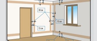
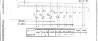
Electricity supply diagram
Approximate power supply diagram for an apartment
In the diagram you can see where the distributors are installed. So, if there are few sockets and switches in the room, then here you can determine where to install additional channels.
Installation of a distribution box: step-by-step instructions
Step 1. First you need to display on the wall the lines where the grooves will go, according to the diagram.
Grilling is performed along these lines
Step 2. Next, in the designated places you need to make recesses for installing the boxes.
It is necessary to secure the box to the wall with self-tapping screws or plaster
Step 3 . Wiring is inserted into the box and connected to each other.
After connecting, check that the wiring is working properly
Step 4. Now all that remains is to close the box with the lid.
Putty is not applied to the decorative cover
Note! They try to secure the cover in such a way that when removing it the surface of the wall is not damaged.
Video - Installation of distribution box
Installation instructions
We already know that installation work can be carried out both openly and hidden. Let's consider the existing main stages of each method separately.
Let us remind you! The most reliable way to connect wires to each other is soldering or special clamps, like car terminals.
Open installation
This method is a simple method that does not take much time. Here are step-by-step instructions that will allow you to install a distribution box in the wall yourself:
- At the first stage, you should turn off the electricity in the house and, for safety, make sure that there is no electricity using an indicator screwdriver. We previously covered how to properly use an indicator screwdriver;
- The attachment points of this product should be marked with a simple pencil;
- The box is attached to the concrete wall using dowels. The design usually provides several special holes for self-tapping screws;
- To enter all groups of wires, it is necessary to cut off the tips of the seals. The cuts are made of a smaller diameter compared to the cable cross-section to better protect the wiring from dust and moisture;
- Connect the wires together. To avoid mistakes, we recommend that you familiarize yourself with the color coding of the wires. All that is required of you is to correctly connect phase to phase, then zero to zero, and then ground to ground (this applies to the socket group). Then you need to connect the introductory group of wires with a group of switches and interior lighting;
- After all work, close the box lid.
As you can see, the process of installing a junction box in concrete is quite simple.
Hidden installation
Although it is much more difficult to install the box in a hidden way, as a rule, novice electricians can cope with this work.
So, let's begin:
- We make special grooves in the concrete wall intended for planting boxes. Perform this work with a drill equipped with a special crown attachment. When performing this work, please pay attention that the diameter of the groove fully corresponds to the dimensions of the product. It happens that the landing space is small. In such cases, it will be necessary to level the contours, and if it turns out to be too large, more solution will have to be applied;
- A line should be drawn to the connection point of the box. The installation height from the ceiling should be 10..20 cm;
- It is necessary to make a solution from alabaster and place it in the groove, but before doing this, moisten it a little with water. You can also use gypsum mortar to seal the grooves;
- We install the box flush on the wall and hold it for a while until the solution sets. After all this, all that remains is to remove the remaining residues with an alabaster spatula;
- Connect the wires together;
- The protective cover closes;
- Cover the installation location with wallpaper or apply a thin layer of finishing plaster to the box lid. If after the work done it is not possible to disguise the cover well, then the wallpaper is cut along the contour and the plastic cover on the light-colored wallpaper will no longer stand out.
Helpful advice never hurts! When you connect the wires to each other, be sure to label each group. This applies to the wires of a socket, switch, chandelier, etc. In case of repair work, you can quickly find the necessary wire.
This completes the work and technology for correct installation of the box with hidden wiring in concrete. With this option, installation time will take a little more, but the appearance of the room will not be spoiled.
Installation and connection diagrams
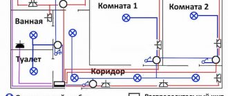
Diagram for normal home wiring
Example of wiring for a private house
Visual diagram with electrical network elements
Wiring diagram through junction box
Methods for connecting wires in a junction box
There are several basic ways to connect the wiring in a junction box. In order to choose one of them, you need to consider the options in more detail.
Stranding and insulation
This is an old, but proven method of connecting wiring over the years. The bottom line is that the ends of the conductors are first stripped of the insulation layer and then twisted together with pliers. After which this place is wrapped with electrical tape.
Twisting conductor strands
This method has advantages:
- ease of installation;
- no need for additional expenses.
However, there are some disadvantages:
- poor-quality connection of cores;
- inability to connect copper and aluminum wires.
It is worth noting that conductors are often connected in this way during temporary installation of electrical wiring. According to safety regulations, the connection method is not suitable for rooms with high humidity levels.
Soldering or welding
It is in these ways that you can make a durable connection of wiring cores. First, their ends are carefully stripped of the insulating layer, then twisted, but without effort. Next, you will need to solder the wires using solder and a soldering iron so that they turn out monolithic. Then you need to wait until they cool naturally, and only then wrap them with electrical tape.
Soldering wire cores
In cases of soldering thick wires, you will need to use a soldering iron with a dense copper tip.
Note! Some would-be craftsmen do not want to wait for the veins to cool naturally, so they cool them under running water. However, this should not be done - microcracks will appear on the surface.
The advantage of soldering is the reliability of the connections, but this method also has some disadvantages:
- the need to purchase a soldering iron;
- this is a labor-intensive process that not every beginner can handle;
- the connection is permanent;
- Over time, the level of resistance in the soldering increases, which leads to voltage leakage.
Often, instead of soldering, the cores are connected by welding. The process has a similar principle, only here a welding machine is already used, so the master must have the appropriate skills.
Video - Soldering twists
Crimping with sleeves
This is also one of the most reliable methods of fixing conductor cores. Here they are placed in a special sleeve and clamped with a crimping tool on both sides. After which this sleeve is wrapped with electrical tape or a cambric is attached to it.
Crimping of conductor cores
It is worth noting that the cores are placed in the sleeve either from different sides or from one. In the case of the first option, they will be connected in the central part of the tube. When choosing the second option, it is necessary to take into account that the diameter of the cores should not exceed the volume of the sleeve.
The advantages of such a connection should be noted:
- reliability;
- affordable cost of sleeves.
Disadvantages of the method:
- The sleeve is used only once. This means that in case of repair, it is torn down and a new one is fixed.
- You will need to use a special tool for high-quality crimping on all sides.
- Wires made of aluminum and copper are crimped only with special tubes, which are difficult to find in stores.
- Electrical installation will take time.
Terminal connection
If the wiring is made of different materials, it is recommended to use special clamps with springs or screws. Connecting the conductors using this method is not difficult; all you need is a screwdriver. The main thing is not to overtighten the bolts.
Connecting wires with clamps
Electrical wiring in the apartment diagram
- If the electrical panel is located in the apartment, the following groups are distinguished:
- lighting of living rooms, kitchens and corridors;
- power supply for living rooms;
- power supply to the kitchen and corridors;
- lighting and power supply for the bathroom.
If the apartment has an electric stove, it must be separated into a separate group.
To increase safety, do not forget to install residual current devices (RCDs), the so-called residual current switches, on each group. They are also required to supply the electrical wiring of the bathroom and kitchen.
After the groups are designed, it is necessary to determine the connection points of all the main consumers of electricity. This includes a washing machine, electric stove, air conditioner, water heater, oven and dishwasher.
Now you can determine the installation locations of switches, lamps, junction boxes and sockets, and then apply them to the draft electrical plan of the apartment. Carefully connect all the circuits and mark the wire lengths.
Be sure to make two copies of the apartment’s electrical plan and put one of them in the family archive with documents. It will come in handy more than once.
Now the final electrical circuit is drawn up. To do this, an exact plan of all rooms is depicted on each sheet, taking into account all dimensions.
All electrical points on the electrical circuit are marked using generally accepted symbols and are connected by lines indicating wires. For better readability, we recommend marking the lighting, grounding and power cables in different colors.
Be sure to mark all distances: linear dimensions of rooms, distances from wires to walls, ceilings, floors, and also to heating systems. Such a diagram will not only be more visual, but it will also be possible to make all the necessary calculations.
Requirements, rules, norms
When drawing up a diagram, you should remember some important requirements for the location of electrical wiring in residential premises.
Do not connect the grounding contacts of sockets to the neutral wires, as well as to the water supply or heating system. This is dangerous for human life. There is a protective ground wire for this purpose.
If the apartment has an electric stove rather than a gas one, then the main circuit breaker must have a rating of at least 63A.
The wires are laid only vertically and horizontally, positioned strictly at right angles to each other.
You should not change their trajectory; in the future, this risks increasing the likelihood of the wires being punctured by a nail or drill when performing minor repair work. Crossing wires should be avoided. If this is not possible, then the distance between them should be more than 3 mm.
When setting dimensions on the plan, it is necessary to ensure that the distance from the cable to the floor or ceiling is at least 150 mm, to window frames, door jambs and corners - at least 100 mm. It is better to place all switches and sockets at the same height.
In this case, switches are installed to the left of the entrance doors at a height of 800-900 mm, and sockets - 250-300 mm. In some cases, such as in the kitchen, the distance may vary. The gap between the heating pipes and wires must be at least 30 mm. Wires are connected to sockets from below, and to switches from above.
Features of installing electrical wiring in rooms with high humidity
Until now, it was believed that installing a socket in a bathroom was prohibited. Indeed, the ban existed until 1996. A bathroom is a room with a damp environment, water taps, a large number of conductive pipelines and a steel bathtub, which poses an increased electrical hazard.
The ban has long been lifted, partly due to the widespread use of modern electrical safety equipment.
- Thus, connecting electrical appliances in a room with high humidity is only possible:
- through a residual current device (RCD) with an operating current not exceeding 30 mA;
- the electrical wiring must have a connected grounding contact (protective zero TN-S);
- sockets should be located no closer than 60 cm from the doors of a closed shower stall;
- at a height of at least 130 cm from the floor level.
How to properly conduct electrical wiring
- It is necessary to draw up an electrical wiring plan for the apartment in two copies:
- on the first one, you should draw a plan for the location of switches and lighting equipment;
- and on the second - sockets.
After this, the clients of the electrical circuit should be divided into groups.
- It might look like this:
- first group – refrigerator and hood (25 A automatic);
- the second is a washing machine (25 A);
- third - lighting fixtures (10 A);
- fourth - sockets (25 A);
- fifth – dishwasher (25 A);
- the sixth is an electric stove (32 A).
- Or like this:
- lighting fixtures for living quarters, kitchen and hallway (10A automatic);
- sockets in living rooms (25 A circuit breaker);
- sockets in the kitchen and hallway (25 A circuit breaker);
- lighting fixtures and sockets in the bathroom (these clients are combined into one group because they work in a humid environment and have serious requirements for them).
For each household equipment, one group is allocated with a 25 or 32 A automatic machine. The equipment is divided into groups due to some nuances.
If all the equipment that consumes electricity is connected to one machine, then you will need a very thick cable that can withstand such a load. You will also have to buy an automatic machine designed for high power, and this will be quite expensive.
If one of the network elements breaks down, you will have to turn off the power to the entire apartment in order to begin restoration work.
When the electrical wiring diagram for a one-room apartment is ready, it is necessary to determine the number of all electricity consumers. You will have to calculate the required number of outlets based on the number of electrically powered equipment you already have, and also take into account future purchases.
Then you need to correctly position all sockets and switches.
- To do this, use the following tips:
- switches and sockets should be placed to the left of the door;
- in living rooms and hallways, sockets should be at a height of 0.4 meters, in the kitchen at a height of 0.95-1.15 meters;
- switches should be located at a height of 0.9 meters;
- It is necessary to mark the locations of switches and sockets in the diagram.
Then you should run the wires from the switches and sockets (meaning the plan). If you are connecting via distribution boxes, then all cables must first go to them, and then to the electrical panel.
- For correct wiring you need to follow the rules:
- cables must run strictly horizontally or vertically;
- It is better to avoid crossing wires;
- the cable must be installed at a distance of 0.15 meters from the ceiling and 0.1 meters from doors and windows;
- the cable to the switch is fed from above, the cable to the socket from below.
The last step will be to calculate the cable footage and the total number of machines. When calculating cable footage, it is necessary to take into account the dimensions of the rooms, and when calculating the number of machines, one must proceed from the number of groups. You should also remember that all machines are ultimately connected to one, which is designed for high power.
If you already use or are planning to purchase an electric stove, then you need an automatic machine that is designed for at least 63 A.
Basic types of wiring
If you decide that you can handle the correct electrical wiring in your apartment, then first you need to choose the appropriate method for this.
There are three types of wiring:
- using distribution boxes;
- star;
- plume.
"Through junction boxes." This is the most common type of wiring. The electrical panel is located on the staircase, and not in the living room. The power cable comes from it, and the panel itself contains a meter and several switches (most often 1-3). In each individual room, power supply is provided through a distribution box located at the entrance.
"Star". Each light point or outlet is located on a separate cable line running into the electrical panel and often has its own circuit breaker.
This wiring makes it possible to exercise full control over each element of the power supply chain. Among the disadvantages for the owner is a significant increase in the amount of necessary wiring and labor costs, the high cost of a fairly large panel, which leads to a significant increase in the cost of the project.
Wiring "Star"
"Plume". The principle is similar to the “star” one, but differs in that not one element, but several are placed on one cable. The project will cost less than the previous one.
It is rare to find one of the options in its “pure form”. In each specific case, they are mixed to achieve the most effective result.
Combined wiring method
Nuances in a one-room apartment
- In a one-room apartment, electrical wiring is most often divided into two groups:
- kitchen and bathroom, where a large number of electrical appliances are concentrated;
- living room.
This is done in order to obtain a power reserve by distributing the total load over two circuits, and also so that in the event of a short circuit or break in the circuit, one line, if possible, remains in working condition.
Electrical wiring diagram in an apartment (examples)
The given diagram of the apartment wiring of a standard two-room apartment with the location of the electrical panel near the entrance to the apartment is made in a somewhat simplified form. Only the main sources of lighting are presented here, that is, chandeliers, simple single-key switches, hidden sockets with a protective contact for grounding.
So, as you can see for yourself, you can create an electrical circuit yourself. A specialist will do this job much better, but every apartment owner should be able to correctly determine the location of the wires in order to avoid accidental damage to them by an unsuccessfully driven nail or drill bit.
Wiring diagrams
It is necessary to become more familiar with the features of connecting the wiring from the junction box to consumers.
Prices for various types of voltage indicators
Voltage indicator
Connecting sockets
Often sockets are connected in groups on one line. So, 3 cables with several conductors are placed inside the box. Brown indicates the phase conductor, blue indicates neutral, and green or yellow indicates ground. Of course, some manufacturers use other colors.
Connecting sockets
The wires are laid out on a flat surface, and then cut to a certain length, but with a margin (so that it can be separated again). Next, it remains to fix them according to the diagram.
Connecting a switch with one button
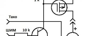
This is where installation becomes more complicated. After all, there are three groups of electrical wiring with different connections. One conductor is responsible for supplying voltage from another box or panel, the second comes from the lighting fixture, and the third from the switch.
The phase conductor is fed to a switch, which is connected to the lamp. Here you should make sure that the voltage supply occurs precisely when the switch is closed. The neutral and grounding conductors from the lamp are connected to the shield.
The principle of connecting a switch with one button
Connecting a switch with two buttons
A three-core cable is connected to this type of switch (without a grounding conductor, because it is connected directly to the panel). The first conductor goes to the common contact of the switch, the second to the first button, and the third to the second button.
Note! The phase conductor is connected to the common contact, the zero is fixed directly from the board and lamps. The phase wires from the lighting fixtures are fixed with the cores on the buttons.
Connecting a switch with two buttons
Degree of protection
In accordance with clause 3.4 of GOST 14254-2015, the degree of protection of distribution boxes is indicated by the IP index on the equipment itself and indicates its resistance to the harmful effects of moisture and dust. Which can disrupt the normal operation of the equipment. The index is followed by a two-digit numerical value indicating the degree of stability of the equipment. Where the first number indicates resistance to penetration of solid particles, and the second indicates resistance to moisture.
According to clause 5.1 of GOST 14254-2015, the first digit can vary from 0 to 6, where each of them means:
- 0 – no protection;
- 1 – prevents contact with live elements of more than 50 mm;
- 2 – does not allow penetration by a finger or objects larger than 12.5 mm;
- 3 – protects against penetration of working tools 2.5 mm;
- 4 – does not allow particles larger than 1 mm to penetrate into the box;
- 5 – dust protection sufficient for full operation of the equipment;
- 6 – dust-proof design.
In accordance with Chapter 6. GOST 14254-2015 the second digit varies in the range from 0 to 9, where each degree indicates:
- 0 – no protection;
- 1 – not afraid of vertically falling drops;
- 2 – prevents drops from entering at an angle of up to 15°;
- 3 – allowed when installed in the rain;
- 4 – may be subject to continuous spraying;
- 5 – water jets are allowed to enter;
- 6 – have protection from powerful pressure;
- 7 – tightness allows temporary immersion;
- 8 – allows long-term immersion;
- 9 – resistant to high-temperature liquids under pressure.
Form
The shape of the boxes can be round, rectangular, or square. Structurally, they do not differ from each other and the choice of shape depends only on the number and thickness of the wires that must be connected to each other and placed inside the box.
Rectangular and especially square ones have a large capacity.