There are a huge number of alternative energy sources on planet Earth. It’s just that humanity has not yet learned how to obtain this energy in cheap ways, although many of them are already in use. Almost all types of alternative energy in theory have been developed and obtained in laboratory conditions. One of these types is energy obtained from an electrolyte located in a magnetic field. This effect is called magnetohydrodynamic, and the installation in which this energy is obtained is an MHD generator. Scientists have known this effect for a long time. It is worth recalling that Faraday in 1832 tried to find an electromagnetic driving force in laboratory conditions. To do this, he used water from the River Thames. Let's look at both positions (effect and oscillator) in more detail.
Intended effect and origin of the name
The first works in this field are attributed to Faraday, who worked in laboratory conditions back in 1832. He investigated the so-called magnetohydrodynamic effect, or rather, he searched for an electromagnetic driving force and tried to successfully apply it. The current of the River Thames was used as a source of energy. Along with the name of the effect, the installation also received its name - magnetohydrodynamic generator.
In this MHD device, there is a direct conversion of one type of energy into another, namely mechanical into electrical. The features of such a process and a description of the principle of its operation as a whole are described in detail in magnetic hydrodynamics. The generator itself was named in honor of this discipline.
Creating a device with your own hands
Obtaining electrical energy in huge quantities without consuming fuel is a tempting and quite feasible idea. The creation of such a device can be considered using the example of the Adams generator. For self-assembly you will need:
- Magnets. The larger the magnet, the more it affects the induction field, as well as the amount of energy generated. For a low-power generator, small pieces are suitable. It is desirable that the sizes be the same. For normal operation, 15 pieces are enough. The positive pole of one magnet must be installed opposite the positive pole of the other. If this condition is not met, then there will be no induction field.
- Copper wires.
- Two coils. You can get them from old engines or wind the wire yourself.
- Sheet steel for making the body.
- Bolts, washers, screws and nails. They are necessary for fastening small elements.
First, the magnet must be secured to the base of the coil. This can be done by drilling a hole in it and then securing it with bolts. The wires on the coils should be 1.25 mm thick and have a layer of insulation. The coils should be mounted on a metal frame so that there are small gaps between the ends. This is required for free rotation of the main element.
At this stage, the device can already be used. It is quite simple to check the correct assembly: you should manually turn the magnets. If the structure is assembled correctly, voltage will arise at the ends of the winding.
This is the most primitive generator, powered by magnets. But based on such a scheme, it is possible to create a device that will be able to provide electricity to the entire house. You can also purchase ready-made devices from trusted manufacturers.
Description of the effect
First of all, you need to understand what happens during the operation of the device. This is the only way to understand the principle of operation of a magnetohydrodynamic generator in action. The effect is based on the appearance of an electric field and, of course, an electric current in the electrolyte. The latter is represented by various media, for example, liquid metal, plasma (gas) or water. From this we can conclude that the operating principle is based on electromagnetic induction, which uses a magnetic field to generate electricity.
It turns out that the conductor must intersect with the field lines. This, in turn, is a prerequisite for flows of ions with charges opposite to the moving particles to begin to appear inside the device. It is also important to note the behavior of the field lines. The magnetic field constructed from them moves inside the conductor itself in the opposite direction from where the ion charges are located.
Relevance
Nature has prepared a countless amount of electricity for us. A huge part of it is concentrated in the world's oceans. The World Ocean contains colossal reserves of energy [1]. So far, people have been able to use only tiny fractions of this energy, and even then at the cost of large and slowly paying off investments, so such energy until now seemed unpromising. However, the very rapid depletion of fossil fuel reserves, the use of which is also associated with significant environmental pollution, forces scientists and engineers to pay increasing attention to the search for harmless energy sources, for example, energy in the World Ocean. The ocean contains several different types of energy: the energy of ebbs and flows, ocean currents, thermal energy, etc. In addition, sea water is a natural electrolyte and contains in 1 liter a myriad of different ions, for example, positive sodium ions and negative ions chlorine The prospect becomes tempting - to place such a device in the natural endless flow of natural sea currents and, as a result, obtain inexpensive electricity from sea water and transmit it to the shore. One such device could be a generator that uses the magnetohydrodynamic effect. This became the topic of the study : “Energy capabilities of the magnetohydrodynamic effect.”
The purpose of the study is to describe, demonstrate and use the magnetohydrodynamic effect. The object of the study is: the movement of charged particles in a magnetic field. Subject of research : magnetohydrodynamic effect, magnetohydrodynamic generator.
To achieve this goal, the following tasks : 1. Conduct a historical and logical analysis of educational, scientific, popular science sources of information. 2. Identify physical laws, principles that explain what the magnetohydrodynamic effect is. 3. Identification of the possibilities of using the MHD effect as an energy resource. 4. Make a model demonstrating the magnetohydrodynamic effect.
To most effectively solve the problems, the following research methods : study of information sources, analysis, generalization method, experiment.
Definition and history of MHD generator
The installation is a device for converting thermal energy into electrical energy. It fully applies the above effect. At the same time, magnetohydrodynamic generators were at one time considered a rather innovative and breakthrough idea, the construction of the first samples of which occupied the minds of leading scientists of the twentieth century. Soon, funding for such projects dried up for reasons that are not entirely clear. The first experimental installations had already been erected, but their use was abandoned.
The very first designs of magnetodynamic generators were described back in 1907-910, however, they could not be created due to a number of contradictory physical and architectural features. As an example, materials have not yet been created that could function normally at operating temperatures of 2500-3000 degrees Celsius in a gas environment. The Russian model was supposed to appear in a specially built MGDPP in the city of Novomichurinsk, which is located in the Ryazan region in close proximity to the state district power station. The project was discontinued in the early 1990s.
Further reading[edit]
- Sutton, George W.; Sherman, Arthur (July 2006). Engineering magnetohydrodynamics
. Dover Construction and Engineering. Dover Publications. ISBN 978-0486450322. - Hugo K. Messerle, Magnetohydrodynamic Power Generation
, 1994, John Wiley, Chichester, Part of the UNESCO Power Engineering Series (this is a source of historical and generator design information). - Shioda, S. "Feasibility Study Results of Closed Cycle MHD Power Plants", Proc. Plasma Tech. Conf., 1991, Sydney, Australia, pp. 189–200.
- R. J. Rosa, Magnetohydrodynamic Energy Conversion
, 1987, Hemisphere Publishing, Washington, DC - G. J. Womac, MHD Power Generation
, 1969, Chapman and Hall, London.
How the device works
The design and principle of operation of magnetohydrodynamic generators for the most part repeat those of ordinary machine versions. It is based on the effect of electromagnetic induction, which means that a current arises in the conductor. This occurs due to the fact that the latter crosses the magnetic field lines inside the device. However, there is one difference between machine and MHD generators. It lies in the fact that for magnetohydrodynamic options the working fluid itself is used directly as a conductor.
The action is also based on charged particles, which are acted upon by the Lorentz force. The movement of the working fluid occurs across the magnetic field. Due to this, flows of charge carriers appear in exactly opposite directions. At the early stage, MHD generators used predominantly electrically conductive liquids or electrolytes. They were the very working fluid. Modern variations have switched to plasma. Positive ions and free electrons became charge carriers for new machines.
MAGNETOHYDRODYNAMIC GENERATOR
- Volume 18. Moscow, 2011, pp. 387-389
Copy bibliographic link:
MAGNETOHYDRODYNAMIC GENERATOR ( MHD generator), an electrical power device in which the thermal energy of a working fluid (liquid or gaseous electrically conducting medium) moving in a magnetic field is directly converted into electricity. DC or AC energy. The movement of such media is described by the equations of magnetohydrodynamics, which gives the device its name. Direct energy conversion - Ch. a feature of M. g., distinguishing it from electric machine generators that convert mechanical. rotational energy received from the prime mover (usually steam, gas turbines or hydraulic turbines, internal combustion engines, etc.) into electrical energy. The process of generating electricity. current in a magnetic field is based on the phenomenon of electromagnetic induction, that is, on the occurrence of a current in a conductor crossing the magnetic field lines; The difference between a magnetic field is that the conductor in it is the working fluid itself, in which, when moving across the magnetic field strength vector, oppositely directed flows of charge carriers of opposite signs arise.
Source
Design of MHD generators
The first node of the device is called the channel along which the working fluid moves. Currently, magnetohydrodynamic generators mostly use plasma as the main medium. The next node is a system of magnets that are responsible for creating a magnetic field and electrodes to remove the energy that will be received during the work process. However, the sources may be different. The system can use both electromagnets and permanent magnets.
The gas then conducts an electric current and is heated to a thermal ionization temperature, which is approximately 10 thousand Kelvin. After this, this indicator must certainly be reduced. The temperature level drops to 2.2-2.7 thousand Kelvin due to the fact that special additives with alkali metals are added to the working environment. Otherwise, the plasma is not sufficiently effective, because its electrical conductivity becomes significantly less than that of the same water.
Advantages
Devices can be purchased ready-made or made independently. Having purchased a wind generator, all that remains is to install it. All adjustments and alignments have already been completed, tests have been carried out under various climatic conditions.
Neodymium magnets, which are used instead of a gearbox and bearings, allow you to achieve the following results:
- friction is reduced and the service life of all parts is increased;
- vibration and noise of the device during operation disappears;
- the cost decreases;
- energy is saved;
- There is no need to regularly service the device.
A wind generator can be purchased with a built-in inverter that charges the battery, as well as a controller.
Typical device operating cycle
It is best to list other components that make up the design of a magnetohydrodynamic generator along with a description of the functional processes in the sequence in which they occur.
- The combustion chamber receives the fuel loaded into it. Oxidizing agents and various additives are also added.
- The fuel begins to burn, allowing gas to be produced as a combustion product.
- Next, the generator nozzle is activated. Gases pass through it, after which they expand, and their speed increases to the speed of sound.
- The action reaches a chamber that passes a magnetic field through it. There are special electrodes on its walls. This is where the gases enter at this stage of the cycle.
- Then the working fluid, under the influence of charged particles, deviates from its primary trajectory. The new direction is exactly where the electrodes are located.
- The final stage. An electric current is generated between the electrodes. This ends the cycle.
Links[edit]
- Kerrebrock, Jack L.; Hoffman, Myron A. (June 1964). “Nonequilibrium ionization due to electron heating. Theory and experiments" (PDF). AIAA Magazine
.
2
(6):1072–1087. Bibcode: 1964AIAAJ…2.1080H. DOI: 10.2514/3.2497. - ↑
Sherman, A. (September 1966).
"Flow in an MHD channel with nonequilibrium ionization" (PDF). Physics of Fluids
.
9
(9):1782–1787. Bibcode: 1966PhFl…. 9.1782S. DOI: 10.1063/1.1761933. - Argyropoulos, G. S.; Demetriades, ST; Kentig, A.P. (1967). "Current distribution in nonequilibrium J×B devices" (PDF). Journal of Applied Physics
.
38
(13):5233–5239. Bibcode: 1967JAP…. 38.5233A. DOI: 10.1063/1.1709306. - Zauderer, B.; Tate, E. (September 1968). "Electrical characteristics of a linear nonequilibrium MHD generator" (PDF). AIAA Magazine
.
6
(9):1683–1694. Bibcode: 1968AIAAJ…6.1685T. DOI: 10.2514/3.4846. - ↑
Velikhov, E.P. (1962).
Hall instability of weakly ionized plasma with current
. 1st International Conference on MHD Energy. Newcastle upon Tyne, England. paragraph 135. Document 47. - ↑
Velikhov, E.P.;
Dykhne A.M. "Plasma turbulence due to ionization instability in a strong magnetic field". In P. Hubert; E. Cremieux-Alkan (ed.). Volume IV. Proceedings of the conference held July 8–13, 1963
. 6th International Conference on Phenomena in Ionized Gases. Paris, France. item 511. Bibcode: 1963pig4.conf..511V. - ↑
Velikhov, E.P.; Dykhne AM; Shipuk, I. Ya. (1965). Ionization instability of plasma with hot electrons (PDF). 7th International Conference on Ionization Phenomena in Gases. Belgrade, Yugoslavia. - Shapiro, G.I.; Nelson, A.H. (April 12, 1978). "Stabilization of ionization instability in an alternating electric field." Letters to the Journal of Technical Physics
.
4
(12): 393–396. Bibcode: 1978PZhTF…4..393S. - Murakami, T.; Okuno, Y.; Yamasaki, H. (December 2005). "Suppression of ionization instability in magnetohydrodynamic plasmas by interaction with a radio frequency electromagnetic field" (PDF). Letters in Applied Physics
.
86
(19):191502–191502.3. Bibcode: 2005ApPhL..86s1502M. DOI: 10.1063/1.1926410. - Petit, J.-P.; Jeffrey, J. (June 2009). "Nonequilibrium plasma instabilities". Acta Physica Polonica
.
115
(6):1170–1173. CiteSeerX 10.1.1.621.8509 . DOI: 10.12693/aphyspola.115.1170. - Petit, J.-P.; Doré, J.-C. (2013). "Elimination of Velikhov's electrothermal instability by changing the value of the electrical conductivity of the streamer by means of magnetic confinement". Acta Polytechnica
.
53
(2):219–222. - Smith BM, Anghaie S, Knight TW (2002). Energy system MHD reactor with a gas core with a cascade power cycle
. ICAPP'02: 2002 International Congress on Advances in Nuclear Power Plants, Hollywood, Florida (USA), June 9-13, 2002. OSTI 21167909. OSTI: 21167909. - ^ab Rohatgi, VK (February 1984). "High Temperature Materials for Magnetohydrodynamic Channels". Bulletin of Materials Science
.
6
(1): 71–82. DOI: 10.1007/BF02744172. Retrieved October 19, 2019. - Bogdancks M, Brzozowski WS, Charuba J, Dabraeski M, Plata M, Zielinski M (1975). "MGD Electric Power Industry". Proceedings of the 6th Conference, Washington, DC
.
2
:9. - Mason T. O., Petuski W. T., Liang W. W., Halloran J. W., Yen F., Pollack T. M., Elliott J. F., Bowen H. K. (1975). "MGD Electric Power Industry" Proceedings of the 6th Conference, Washington, DC
.
2:77
. - Bajovich, Valentina S. (1994). "Correct quasi-one-dimensional model of fluid flow in a segmented Faraday channel of an MHD generator." Energy conversion and control
.
35
(4): 281–291. DOI: 10.1016/0196-8904 (94) 90061-2. - Bajovich, Valentina S. (1996). "A reliable tool for calculating the shape and dimensions of a segmented channel of an MHD Faraday generator." Energy conversion and control
.
37
(12):1753–1764. DOI: 10.1016/0196-8904 (96) 00036-2. - "MESSERL, Hugo Karl". Australian Academy of Technological Sciences and Engineering (ATSE)
. Archived from the original on 2008-07-23.. - Donald G. Ink, H. Wayne Beatty (editor), Standard Manual for Electrical Engineers, 11th Edition
, Mc Graw Hill, 1978 ISBN 0-07-020974-X pp. 11–52
Basic classifications
There are many options for the finished device, but the principle of operation will be virtually the same in any of them. For example, it is possible to run a magnetohydrodynamic generator using solid fuels such as fossil combustion products. Also, vapors of alkali metals and their two-phase mixtures with liquid metals are used as an energy source. Based on the duration of operation, MHD generators are divided into long-term and short-term, and the latter into pulsed and explosive. Heat sources include nuclear reactors, heat exchangers and jet engines.
In addition, there is also a classification based on the type of duty cycle. Here the division occurs into only two main types. Open cycle generators have a working fluid mixed with additives. Combustion products pass through the working chamber, where they are cleaned of impurities in the process and released into the atmosphere. In a closed cycle, the working fluid enters the heat exchanger and only after that enters the generator chamber. Next, the combustion products wait for the compressor, which completes the cycle. After this, the working fluid returns to the first stage in the heat exchanger.
Winding method for windmill stator coil
The coils should be wound with thicker wires if possible in order to reduce the resistance in them. This can be done on a mandrel or on a homemade machine.
In order to figure out what power potential the generator has, spin it with one coil, since, depending on how many neodymium magnets are installed and what their thickness is, this indicator may differ significantly. The measurements are carried out without load at the required number of revolutions. For example, if a generator at 200 rpm provides a voltage of 30 V, having a resistance of 3 ohms, then subtract 12 V (battery supply voltage) from 30 V and the resulting result is 18 divided by 3 (resistance in ohms) we get 6 ( current in amperes), which will go from the wind generator to charge the battery. However, as practice shows, due to losses in the wires and diode bridge, the actual indicator that the magnetic axial generator will produce will be less.
The thickness of the stator should be the same as the magnets. The form for it is usually plywood; for strength, fiberglass is placed under the coils and on top of them, and the whole thing is filled with epoxy resin. In order to prevent the resin from sticking to the mold, the latter is lubricated with any fat or adhesive tape is used. The wires are first brought out and fastened together, the ends of each phase are then connected with a triangle or an asterisk.
Main characteristics
If the question of what a magnetohydrodynamic generator produces can be considered fully illuminated, then the main technical parameters of such devices should be presented. The first of these in importance is probably power. It is proportional to the conductivity of the working fluid, as well as the squares of the magnetic field strength and its speed. If the working fluid is a plasma with a temperature of about 2-3 thousand Kelvin, then the conductivity is proportional to it to the 11-13th power and inversely proportional to the square root of the pressure.
Data on flow speed and magnetic field induction should also be provided. The first of these characteristics varies over a fairly wide range, from subsonic speeds to hypersonic speeds up to 1900 meters per second. As for the magnetic field induction, it depends on the design of the magnets. If they are made of steel, then the upper bar will be set at 2 Tesla. For a system that consists of superconducting magnets, this value increases to 6-8 Tesla.
PRACTICAL PART
You can demonstrate the MHD effect using the following set of materials : 1. Magnet; 2. Salt; 3. Pepper; 4. Battery; 5. Copper wires.
Work progress: 1. Make an aqueous solution of salt and add pepper. This is necessary so that the movement of fluid flows can be seen. 2. Place a small vessel with the prepared solution on a magnet. 3. We lower the ends of the copper wire, connected at the other ends to the poles of the battery, into the prepared solution (photo 1). 4. We observe the movement of fluid flows between the ends of the copper wire.
Explanation: A salt solution is a conductor of electric current - an electrolyte. The electrolyte will move in a magnetic field under the influence of the Lorentz force. This is the MHD effect.
Using the phenomenon of the MHD effect, a boat was manufactured on an MHD drive [8]. The materials used are shown in photo 2, the finished boat is shown in photos 3 and 4.
The boat will move due to the movement of the electrolyte in the magnetic field. Thus, we can conclude that MHD electricity, despite all the difficulties, will come to the service of man and people will learn to fully use the energy of the ocean. After all, this is simply necessary for modern humanity, because according to scientists’ calculations, fossil fuel reserves are running out literally before the eyes of the living inhabitants of planet Earth!
Application of MHD generators
We do not see widespread use of such devices today. Nevertheless, it is theoretically possible to build power plants with magnetohydrodynamic generators. There are three valid variations:
- Fusion power plants. They use a neutron-free cycle with an MHD generator. It is customary to use plasma at high temperatures as fuel.
- Thermal power plants. An open cycle type is used, and the installations themselves are quite simple in design features. This option still has prospects for development.
- Nuclear power plants. The working fluid in this case is an inert gas. It is heated in a closed cycle nuclear reactor. It also has prospects for development. However, the possibility of application depends on the emergence of nuclear reactors with a working fluid temperature above 2 thousand Kelvin.
Magnetic motor
There is the concept of perpetual motion machines of the first order and the second. The first order is devices that produce energy on their own, from the air, the second type is engines that need to receive energy, it can be wind, sun rays, water, etc., and they convert it into electricity. According to the first law of thermodynamics, both of these theories are impossible, but many scientists do not agree with this statement, who began the development of second-order perpetual motion machines operating on the energy of a magnetic field.
Photo – Dudyshev magnetic motor
A huge number of scientists at all times worked on the development of a “perpetual motion machine”; the greatest contribution to the development of the theory of a magnetic engine was made by Nikola Tesla, Nikolai Lazarev, Vasily Shkondin, and the variants of Lorenz, Howard Johnson, Minato and Perendeva are also well known.
Photo – Magnetic Lorentz motor
Each of them has its own technology, but they are all based on a magnetic field that is formed around the source. It is worth mentioning that engines do not exist in principle, because... magnets lose their abilities after approximately 300-400 years.
The simplest is considered to be a homemade anti-gravity magnetic Lorentz engine. It works by using two differently charged disks that are connected to a power source. The disks are half placed in a hemispherical magnetic screen, the field of which begins to gently rotate them. Such a superconductor very easily pushes the MP out of itself.
The simplest Tesla asynchronous electromagnetic motor is based on the principle of a rotating magnetic field, and is capable of producing electricity from its energy. An insulated metal plate is placed as high above ground level as possible. Another metal plate is placed in the ground. A wire is passed through a metal plate on one side of the capacitor and the next conductor goes from the base of the plate to the other side of the capacitor. The opposite pole of the capacitor, being connected to ground, is used as a reservoir for storing negative energy charges.
Photo – Tesla Magnetic Motor
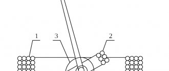
Lazarev's rotary ring is so far considered the only working VD2, in addition, it is easy to reproduce, you can assemble it with your own hands at home, using available tools. The photo shows a diagram of a simple Lazarev ring engine:
Photo – Koltsar Lazarev
The diagram shows that the container is divided into two parts by a special porous partition; Lazarev himself used a ceramic disk for this. A tube is installed in this disk, and the container is filled with liquid. For the experiment, you can even pour plain water, but it is advisable to use a volatile solution, for example, gasoline.
Prospects of devices
The relevance of magnetohydrodynamic generators depends on a number of factors and still unresolved problems. As an example, we can cite the ability of such devices to generate only direct current, which means that to service them it is necessary to design sufficiently powerful and, moreover, economical inverters.
Another visible problem is the lack of necessary materials that could work for a sufficiently long time when the fuel is heated to extreme temperatures. The same applies to the electrodes used in such generators.
CONTENT
- 1 Principle
- 2 Electricity generation 2.1 Faraday generator
- 2.2 Hall generator
- 2.3 Disk generator
- 2.4 Generator efficiency
- 2.5 Problems with materials and design
- 2.6 Economy
- 2.7 Toxic by-products
- 3.1 Development of the former Yugoslavia