What is an asynchronous motor and its principle of operation
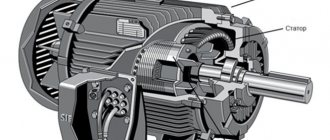
Any electric motor is a device for converting electrical energy into mechanical energy. An electric motor consists of a stationary part (stator) and a moving part (rotor). The structure of the stator is such that it looks like a hollow cylinder, inside of which there is a winding. A moving part, the rotor, is inserted into this cylindrical hole. It also has the appearance of a cylinder, but is smaller in size. There is an air gap between the stator and the rotor, allowing the rotor to rotate freely. The rotor rotates due to currents induced by the magnetic field of the stator. Based on the method of rotation, motors are divided into synchronous and asynchronous.
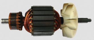
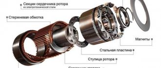
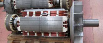
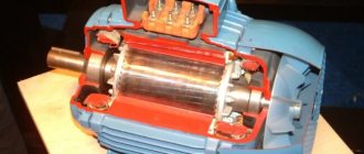
This is what a disassembled asynchronous motor with a squirrel-cage rotor looks like
An asynchronous electric motor differs in that the rotation speed of the rotor and the magnetic field created by the stator are unequal. That is, the rotor rotates asynchronously with the field, which gives this type of machine its name. Typically, in operating mode its rotation speed is lower. The second name for this type of motor is induction. This name is due to the fact that the movement occurs due to induction currents induced on it.
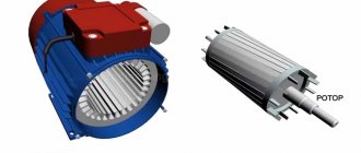
Asynchronous motor disassembled: main components and parts
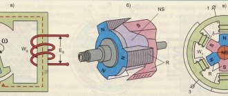
The operating principle of an asynchronous motor can be briefly described as follows. When the motor is turned on, current is supplied to the stator windings, which creates an alternating magnetic field. The rotor enters the area of action of the power lines and begins to rotate following the alternating field of the stator.
What are the main parts of this machine?
Having disassembled a three-phase asynchronous motor, you can observe two main elements.
1. Stator.
2. Rotor.
One of the most important parts is the stator. In the photo above, this part of the engine is located on the left. It consists of the following main elements:
1. Body. It is necessary to connect all parts of the machine. If the engine is small, then the housing is made of one piece. The material used is cast iron. Steel or aluminum alloys are also used. Sometimes the housing of small engines combines the functions of the core. If the engine is large in size and power, then the housing is welded from separate parts.
2. Core. This engine element is pressed into the housing. It serves to improve the quality of magnetic induction. The core is made of electrical steel plates. In order to reduce losses inevitable when eddy currents appear, each plate is coated with a layer of special varnish.
3. Winding. It is placed in the grooves of the core. Consists of coils of copper wire, which are assembled into sections. Connected in a certain sequence, they form three coils, which together form the stator winding. It connects directly to the network, which is why it is called primary.
The rotor is the moving part of the engine. In the photo it is on the right. It serves to convert the force of magnetic fields into mechanical energy. The rotor of an asynchronous motor consists of the following parts:
1. Shaft. Bearings are attached to its shanks. They are pressed into shields that are bolted to the end walls of the stator box.
2. The core, which is assembled on the shaft. It consists of special steel plates, which have such valuable properties as low resistance to magnetic fields. The core, having the shape of a cylinder, is the basis for laying the armature winding. The rotor, or, as it is also called, the secondary winding receives energy thanks to the magnetic field that appears around the stator coils when electric current passes through them.
Stator
The stator of an asynchronous motor consists of three parts: housing, core and winding. The stator housing serves as a support for the electric motor. It is made of steel or cast iron, by welding or casting. High demands are placed on the strength of the housing, since during operation vibrations occur, which can result in the rotor moving, which will lead to jamming of the motor and its failure.
Asynchronous motor stator
There is one more requirement - the geometry of the body must be ideal. The gap between the stator winding and the rotor is made of several millimeters, so the slightest deviations can be critical.
Stator core
The stator core of an asynchronous electric motor is made of stacked metal plates. Since the core is a magnetic circuit, the metal used is magnetic electrical steel. To reduce losses due to eddy flows, the core is made of plates coated with a layer of dielectric (varnish).
The stator core is made up of thin insulated metal plates
The thickness of one plate is 0.35-0.5 mm. They are assembled into a single package so that the grooves of all plates coincide. The winding turns are then placed into these slots.
Stator winding and motor speed
The stator of an asynchronous electric motor most often has a three-phase field winding. It is called so because it causes the rotor to move. The stator winding consists of coils wound from copper wire that fit into the grooves of the core. Each winding can consist of several turns of wire or one turn. A special wire is used, with a varnish coating, which insulates the turns from each other and from the walls of the core.
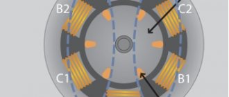
As already mentioned, most often the stator winding of an asynchronous motor has three phases. In this case, the axes of the coils are located with a shift of 120°. With this structure, the magnetic field has two poles and makes one full revolution per cycle of three-phase power. With a power supply frequency of 50 Hz, the rotation speed of the field (and rotor) is 50 rpm or 3000 rpm.
Laying the stator winding coils of an asynchronous motor
To reduce the rotor speed in an asynchronous motor, the winding is made with a large number of poles. So with a four-pole starter, the rotation speed will be half as much - 1500 rpm. A winding with six stator poles gives a three times lower speed - 1000 rpm. With eight poles - four times less, i.e. 750 rpm. Even “slower” electric motors are made very rarely.
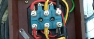
The ends of the stator windings are led out to the terminal box of the housing. Here they can be connected according to the “star” or “delta” principle, depending on the type of power supplied (220 V or 380 V).
Device
By definition, “asynchronous” is an AC motor whose rotor rotates slower than the stator’s magnetic field, that is, asynchronously. But this definition is not very informative. To understand it, you need to understand how this engine works.
An asynchronous motor, like any other, consists of two main parts - a rotor and a stator. Let’s decipher “for dummies” in electrics:
- The stator is the stationary part of any generator or electric motor.
- The rotor is the rotating part of the engine, which drives the mechanisms.
The stator consists of a housing, the ends of which are closed by bearing shields in which bearings are installed. Depending on the purpose and power of the engine, plain or rolling bearings are used. There is a core in the housing, and a winding is installed on it. It is called the stator winding.
Since the current is alternating, in order to reduce losses due to stray currents (Foucault currents), the stator core is made of thin steel plates, isolated from each other by scale and fastened with varnish. The stator windings are supplied with supply voltage, the current flowing in them is called the stator current.
The number of windings depends on the number of supply phases and the design of the motor. So a three-phase motor has at least three windings connected in a star or delta circuit. Their number may be greater, and it affects the speed of rotation of the shaft, but we will talk about this later.
But things are more interesting with the rotor; as already mentioned, it can be either short-circuited or phase-type.
A squirrel-cage rotor is a set of metal rods (usually aluminum or copper), indicated by the number 2 in the figure above, soldered or poured into a core (1) and closed with rings (3). This design resembles a wheel in which domesticated rodents run, which is why it is often called a “squirrel cage” or “squirrel wheel” and this name is not slang, but quite literary. To reduce higher harmonics of the EMF and pulsation of the magnetic field, the rods are placed not along the shaft, but at a certain angle relative to the axis of rotation.
The phase rotor differs from the previous one in that it already has three windings, like a stator. The beginnings of the windings are connected to rings, usually copper, they are pressed onto the motor shaft. Later we will briefly explain why they are needed.
In both cases, one of the ends of the shaft is connected to the driven mechanism, it is made of a conical or cylindrical shape with or without grooves, to install a flange, pulley and other mechanical drive parts.
An impeller, which is necessary for blowing and cooling, is attached to the “back” part of the shaft; a casing is placed on top of the impeller on the housing. Thus, cold air is directed along the ribs of the asynchronous motor; if for some reason this impeller does not rotate, it will overheat.
The design of the first asynchronous motor was developed by M.O. Dolivo-Dobrovolsky and he patented it in 1889. It has survived to the present day without any special changes.
Rotor
The rotor of an asynchronous electric motor comes in two types: squirrel-cage and phase. Most often there are machines with a squirrel-cage rotor. Their advantage is their simplicity of design and uncomplicated manufacturing technology. What is also important is that in such motors there is no contact with the dynamic structure. This increases durability and makes maintenance less frequent and easier.
An asynchronous motor can be squirrel-cage or phase-cage
Asynchronous electric motors with a wound rotor have a more complex design. But they allow you to smoothly regulate the speed without additional devices, and have high torque from the start. So you have to choose: a simpler design or the ability to adjust the rotation speed.
Squirrel-cage rotor device
The rotor consists of a shaft and a cylindrical structure of squirrel-cage rods. Externally, this design is very similar to a squirrel wheel, which is why it is often called a short-circuited rotor winding.
Squirrel-cage rotor device
Initially, both the rods and the end rings were made of copper. The rotors of modern asynchronous motors with power up to 100 kW are made of aluminum rods, with aluminum closing disks. The distance between the rods is again filled with aluminum alloy. The result is a squirrel-cage rotor, but with a continuous coating.
Since a significant amount of heat is generated during operation, the squirrel wheel jumpers are made with additional ventilation blades for cooling. This is how self-cooling occurs during operation. The higher the rotation speed, the more efficient it works.
How an asynchronous motor works: design and arrangement of parts
The rotor is installed in the stator, the ends of the shaft are fixed using covers with mounted bearings. This is a brushless (brushless) motor. No additional contacts or electrical connections. The moving part of the motor begins to rotate in the presence of a magnetic field on the stator. It occurs after power is applied. This field rotates, causing objects that are in its field to rotate. A simple and reliable design, which determined the popularity of electric motors of this type.
How a wound rotor is made
The structure of the phase rotor is not much different from the stator winding. The same type-setting rings with grooves for laying copper coils. There are three rotor windings, they are usually connected by a star.
This is what a wound rotor of an asynchronous motor looks like
The ends of the rotor windings are attached to copper slip rings. These rings are rigidly fixed to the shaft. In addition, they are necessarily insulated from each other and have no electrical contact with the steel shaft (attached to the rod through dielectric spacers). Since the presence of rings is a distinctive feature of this type of engine, they are sometimes called ring engines.
Asynchronous motor with wound rotor
To fix the rotor to the stator housing, two covers with bearings are made. Brushes are attached to one of the covers, which are pressed against the rings on the shaft, due to which they have good contact with them. To regulate the rotation speed, the brushes are connected to a rheostat. By changing its resistance, we change the voltage, and with it the rotation speed.
Which is better short-circuited or phase-circuited?
Despite the fact that motors with a phase rotor start better and allow you to smoothly change the speed during operation using a conventional rheostat, squirrel-cage motors are more often used. This design does not have brushes, which are the first to fail. In addition, a simpler design of the moving part reduces the cost of the engine, the unit lasts longer, and maintenance and servicing are easier.
Which is better: squirrel-cage rotor or phase rotor
However, it is worth taking a closer look at the advantages and disadvantages of both types of asynchronous motors. So, the advantages of a squirrel-cage asynchronous motor:
- Simple design.
- Easy maintenance.
- Higher efficiency.
- No sparking.
Flaws:
- Low starting torque.
- High starting current (4-7 times higher than the rated current).
- There is no way to adjust the speed.
The magnetic field of the three-phase stator pushes the rotor
Due to the high starting current, direct switching is permitted for motors up to 200 kW. More powerful ones require ballasts. Usually a frequency converter is used, which smoothly increases the current, providing a smooth start without overloads.
Advantage of asynchronous phase motor:
- Quick and hassle-free start.
- Allows you to change the speed during operation.
- Direct connection is possible with virtually no power limitation.
There are also disadvantages: the presence of brushes, the possibility of sparking, complex and frequent maintenance.
How is the speed adjusted?
As already written, the rotor speed depends on the number of stator poles. The greater the number of poles, the lower the speed. But this is not the only way to regulate the rotation speed. It also depends on the supply voltage and frequency.
Methods for regulating the frequency of an asynchronous motor
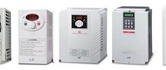
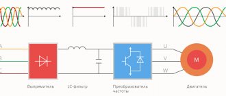
The voltage can be adjusted by installing a potentiometer at the input. The frequency is regulated by installing a frequency converter. A frequency converter is a more profitable solution, since it also reduces starting currents and can be programmable.
Kinds
Asynchronous motors (IM) are divided into two main groups:
- with a squirrel-cage rotor (SC);
- with a wound rotor.
If we omit the nuances, the difference is that an IM with a squirrel-cage rotor does not have brushes and pronounced windings, it is less demanding in maintenance. Whereas in asynchronous motors with a wound rotor there are three windings connected to slip rings, the current from which is removed by brushes. Unlike the previous one, it is better able to regulate the torque on the shaft and it is easier to implement a smooth start to reduce starting currents.
Otherwise, engines are classified:
- by the number of supply phases - single-phase and two-phase (used in everyday life when powered from a 220V network), and three-phase (most widely used in production and workshops).
- according to the mounting method - flange or foot-mounted.
- by operating mode - for long-term, short-term or intermittent operation.
And a number of other factors that influence the choice of a specific product for use in specific conditions.
There is a lot to be said about single-phase electric motors: some of them are started via a capacitor, and some require both a starting and running capacitor. There are also options with a short-circuited turn, which operate without a capacitor and are used, for example, in hoods. If you are interested, write in the comments and we will write an article about it.
Single phase asynchronous motor
A three-phase asynchronous motor was considered above; there are two of them in a single-phase asynchronous motor. One is working, the second is auxiliary. The auxiliary is needed in order to give initial rotation to the rotor. Therefore it can also be called starting or starting.
A single-phase asynchronous motor has two windings: working and auxiliary (starting or cranking)
When one winding in the stator is turned on, it creates two equal magnetic fields rotating in different directions. If you introduce a rotor into this field that already has some initial rotation, the magnetic field will maintain this rotation. But how to start the rotor at the start? How to give it rotation, because from one winding two equal magnetic fields arise, directed in different directions. So it is impossible to make the rotor rotate with their help. In the simplest version, rotation is set manually - mechanically. The rotation then picks up the field.
To automate the start of a single-phase asynchronous motor, an auxiliary winding was made. It is designed in such a way that it suppresses one of the components of the magnetic field of the main winding and enhances the second. Accordingly, one of the components outweighs, setting the rotation of the rotor. Then the starting winding is turned off, and the main winding maintains rotation.
How to connect the motor to a power source
To start an asynchronous motor, it must be connected to a three-phase current network. The asynchronous motor circuit is assembled in two ways. The figure shows the connection diagram of the motor leads, in which the stator windings are assembled in a star manner.
This figure shows another connection method called a "triangle". The circuits are assembled in a terminal box attached to the housing.
You should know that the beginnings of each of the three coils, they are also called phase windings, are called C1, C2, C3, respectively. The ends, which are named C4, C5, C6, are signed similarly. If there are no pin markings in the terminal box, then you will have to determine the beginnings and ends yourself.
