Purpose
The inductive sensor is designed to control the movement of the working element without direct contact with it. The main areas of application for it are machine tools, precision medical devices, process automation systems, measurement and control of product shape. In accordance with the provisions of clause 2.1.1.1 of GOST R 50030.5.2-99, this is a sensor that creates an electromagnetic field in the sensitivity area and has a semiconductor switch.
The scope of application of inductive sensors is largely determined by their high reliability and resistance to external factors. Their readings and operation are not affected by many environmental factors: moisture, condensation, accumulation of dust and dirt, ingress of solid particles. Such features are provided by their design and design data.
Areas of application
The areas of use of miniature devices are extensive:
- Used in mechanical engineering for assembly, testing, packaging, welding, rivets.
- In laboratories they are used for control and measurement.
- Automotive technology, transport industry, mobile equipment. The most popular is the neutral gear sensor for manual transmissions. Many vehicle control systems contain sensors. They are found in the steering mechanism, valves, pedals, in engine compartment systems, in control systems for mirrors, seats, and folding roofs.
- They are used in robot designs, in the scientific field and in education.
- Medical technology.
- Agriculture and special equipment.
- Woodworking industry.
- Metalworking area, in metal-cutting machines.
- Wire production.
- Designs of rolling mills, in machines with program control.
- Tracking systems.
- In security systems.
- Hydraulic and pneumatic systems.
Device
The development of the radio electronics segment has led not only to the improvement of the original mechanisms, but also to the emergence of fundamentally new inductive sensors. As an example, consider one of the simplest options (Figure 1):
Rice. 1. Inductive sensor device
As you can see in the figure, it includes:
- magnetic core or yoke (1) – designed to transmit the electromagnetic field from the generator to the sensitivity zone;
- inductor (2) – creates an alternating electromagnetic field when electric current flows through the turns;
- measurement object (3) – a metal armature inserted or moved into the sensitivity area; non-metallic objects are not capable of influencing the state of the electromagnetic field, therefore they are not used as a detector;
- the gap between the measurement object and the main magnetic circuit (4) – provides a measure of interaction as a magnetic dielectric; depending on the sensor model and the method of movement, it can remain unchanged or fluctuate within a given range;
- generator (5) - designed to generate an electrical voltage of a given frequency, which will create an alternating magnetic field in a given area.
What to pay attention to
Before starting the procedure for replacing the speed sensor, you need to turn off the ignition, since the presence of voltage in the circuit when connecting a voltmeter can lead to a short circuit and failure of other elements. In order to avoid encountering rod defects when removing the speed sensor, it is necessary to dismantle the speedometer drive. To remove it, use a regular wrench. The procedure should be carried out very carefully, removing the drive from the body of the gearbox, and it is important not to lose the rod in the place of the manual transmission.
Principle of operation
The principle of operation of an inductive sensor is the ability of the electromagnetic field to change its parameters, depending on the value of magnetic conductivity along the flow path. Its operation is based on the classic version of a coil wound on a core.
Rice. 2. Magnetic field at rest
When electric current I flows through the turns of this coil, a magnetic field is generated (see Figure 2), the resulting magnetic induction vector B of which is determined by the Right Hand Rule. When the magnetic field moves along the core, the ferromagnetic material provides maximum throughput. But as soon as the magnetic induction lines enter the airspace, the magnetic conductivity deteriorates significantly and part of the field is dissipated.
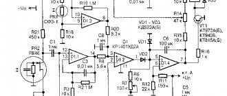
Rice. 3. Magnetic field when introducing a trigger object
When a triggering object (Figure 3) made of metal is brought into the field of action of an inductive sensor, the intensity of the induction lines changes sharply. As a result, the flux increases and its value changes, and this, in turn, leads to a change in the electrical value in the coil circuit due to the phenomenon of mutual induction. In practice, this signal is too small, so to expand the measurement limit of the inductive sensor, an amplifier is included in their circuit.
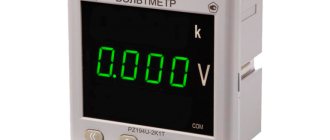
Self-test
Every car owner should know how to check the speed sensor . There are three possible ways to determine if it is working properly. Before starting diagnostics, you should determine whether the sensor produces 12 V, since the basic principle of operation of the internal combustion engine is based on the Hall effect, the state of the contacts occurs exclusively during rotation. The voltage readings of the sensor in operating condition should be within 0.5-10 V. 1. Check with a voltmeter. The DSA needs to be removed and it will be determined what each terminal is responsible for. One contact of the voltmeter should be connected to the terminal that outputs pulse signals, and the second should be connected to the ground wire. The sensor must be rotated and at this time look at the voltage readings. The more intense the sensor rotates, the higher the readings will be. 2. It is necessary to disconnect the impulse wire, which is detected by a special controller, and lift the wheel to rotate with a jack so that it does not touch the ground. Connect the “Signal” control wire; if the indicator is “-“, then the speed sensor is working. A wire with a light bulb can replace the control in this method. 3. To determine the operation of the sensor, it is not necessary to remove it from the machine; to do this, you can lift it, as in the previous method. Next, connect the voltmeter to the sensor contacts; the device will display voltage readings when the wheel rotates. If the voltmeter shows voltage and frequency in Hz, this indicates that the DS is working.
Sensing distance and target
Depending on the design and operating principle of the inductive sensor, the object of influence may have vertical or horizontal movement relative to the meter itself. However, the sensor’s response to the start of movement of the controlled object may not begin immediately, which is determined by the nominal distance at which the sensor’s sensitivity zone is ensured and the technical parameters of the object.
Rice. 4. Trigger area and object
As you can see in Figure 4, in the first position the controlled object is located at a distance where the electromagnetic lines do not reach its surface. In this case, the signal will not be collected from the inductive sensor, since it does not detect movements in the sensitivity zone. In the second position, the controlled object has already crossed the sensing distance and entered the sensitive zone. As a result of interaction with the object, a corresponding signal will appear at the sensor output.
Also, the sensing distance will depend on the geometric dimensions, shape and material. It should be noted that only metal objects are used as an object for triggering an inductive sensor, but the moment the sensor transitions to the opposite state will also differ from the specific type, which is shown in the diagram:
Rice. 5. Dependence of the sensing distance on the material
How to check DS?
First, we check for the presence of grounding and 12 V voltage in the contacts. Such contacts are checked by dialing. And the contact of the pulse signals is checked during torsion.
The voltage between the output and the ground of the working speed sensor ranges from 0.5 V to 10 V.
There are several ways to check your car's speed sensor:
- No. 1 Using a voltmeter.
- No. 2 Without removing the sensor from the car.
- No. 3 Using a light bulb or control.
Checking with a voltmeter:
- Remove the sensor.
- Connect one contact to the pulse signal terminal. We connect the second contact to the ground of the car.
- Next, we turn the speed sensor and see if signals are sent when the cycle is running and measure the output voltage of the DC. To rotate the sensor axis with your own hands, you need to put a tube on the sensor axis and twist it at a speed of up to 5 km/h. The faster you rotate the sensor axis, the more voltage the voltmeter will show.
Without removing the sensor from the car
- We put the car on a jack (jack up one wheel).
- We connect a voltmeter to the contacts of the car speed sensor.
- Spin the raised wheel and see if tension appears. A working sensor should show voltage and frequency (Hertz).
Using a light bulb or control
- Disconnect the pulse data wire from the sensor.
- We jack up one wheel.
- Turn on the ignition and look for “+” and “-“ using the control.
- Use the control to connect the “Signal” wire and turn the wheel by hand. If the sensor is working properly, the control should show a “-” (minus) signal.
Kinds
In practice, there is a huge variety of inductive sensors, all of them can be divided into two large categories, depending on the type of supply current - alternating and direct. Depending on the state of the contacts in accordance with Table 1 p.3 of GOST R 50030.5.2-99, inductive sensors are:
- closing – when moving the controlled object, it is switched to the on position;
- opening – in case of impact, the inductive sensor moves the contacts to the off position;
- switching - simultaneously combines both previous options, in one switching it moves one output to the on position, the second to the off position.
Based on the number of measuring circuits, inductive sensors are divided into single and differential. The first of them has one coil and one measuring circuit. The second type involves the presence of two sensors, the measuring circuits of which are switched in antiphase to compare readings.
Rice. 6. Single and differential sensor
Based on the method of data transmission, inductive sensors are divided into analog, electronic and digital. In the first case, the same coils and ferromagnetic cores are used. Electronic ones use a Schmidt trigger instead of ferromagnets to produce a hysteresis component. Digital ones are made in the format of printed circuit boards on microcircuits. In addition, the types are divided by the number of sensor pins: two, three, four or five.
Main causes of malfunction
A speed sensor breakdown should be repaired in a timely manner before it develops into an expensive repair. To do this, every car owner must monitor how his vehicle behaves while driving. At the slightest deviation from the established norm, it is recommended to replace the DSA. The main symptoms of a speed sensor malfunction:
- fuel consumption increases;
- incorrect speedometer readings;
- the engine is unstable at idle;
- the motor does not develop full power.
Also, signs of speed sensor failure may appear in situations where the engine stops working at idle, while squeezing the clutch, or while shifting gears. In this case, the driver will see an indicator with the words “Check engine”; if there is a computer, the display will show error “24”. In this situation, the first step is to check the condition of the contacts and wires; perhaps an open circuit will be detected. As a rule, this occurs near the connector where there is a bend, and the wires can fray. If the contacts are simply dirty or oxidized, they need to be cleaned. You also need to monitor the integrity of the wire insulation at the exhaust manifold. A sensor malfunction may be caused by a failure of the speedometer cable, which has become worn out during operation.
Characteristics (parameters)
When choosing an inductive sensor to solve a specific problem, they are guided by the parameters of the circuit in which it will operate and the basic logic of the circuit. Therefore, the compliance of their parameters must be checked:
- supply voltage - determines the permissible minimum and maximum potential difference at which the inductive sensor operates normally;
- minimum operating current – the lowest load value at which switching will occur;
- actuation distance - the permissible distance distance at which switching will occur;
- inductive and magnetic resistance - determines the conductivity of electric current and magnetic induction lines for a specific model;
- correction factor - used to make corrections, depending on additional factors;
- switching frequency – the maximum possible number of switching times per second;
- overall dimensions and installation method.
Hall sensors for measuring linear movements (Linear Hall Sensors)
In many applications, the task arises of determining the position of an object moving along a certain trajectory, which does not necessarily have to be rectilinear. The controlled object can be, for example, a pedal or steering column of a car, a throttle valve of the fuel system of an internal combustion engine (Figure 11), a linear actuator of an industrial robot, a liquid level meter rod and many other applications containing moving parts, the position of which can take any value in some limited space.
Rice. 11. Magnetic field configuration of magnetic sensor for detecting car engine throttle position
Obviously, in such applications it is necessary to measure the absolute value of the magnetic field, which depends both on the magnitude of the induction of the external magnet and on the distance between it and the sensor. This means that these systems must have the ability to calibrate, with the help of which all the specific features of a particular unit can be accurately taken into account. That is why most linear sensors manufactured by Infineon (Table 6), in addition to the measuring part, contain units for processing measurement results taking into account correction factors stored in the built-in non-volatile memory (Figure 12).
Rice. 12. Block diagram of TLE4998 sensors
Table 6. Technical characteristics of Infineon linear sensors
| Name | Sensitivity | Cut-off induction, µT | Supply voltage (extended range), V | Automotive version | Interface | Frame |
| TLE4997 | ±12.5…±300 mV/mT | < ±400 | 5 ±10% (7) | + | Analog | SSO-3-10, TDSO-8 |
| TLE4998P | ±0.2…±6%/mT | < ±400 | 5 ±10% (16) | + | PWM | SSO-3-10, SSO-4-1, SSO-3-9, TDSO-8 |
| TLE4998S | ±8.2…±245 LSB/mT | < ±400 | 5 ±10% (16) | + | SENT | SSO-3-10, SSO-4-1, SSO-3-9, TDSO-8 |
| TLE4998C | ±8.2…±245 LSB/mT | < ±400 | 5 ±10% (16) | + | SPC | SSO-3-10, SSO-4-1, SSO-3-9, TDSO-8 |
Two-wire inductance sensors
Rice.
7. Connection diagram for a two-wire sensor As you can see in the diagram above, two-wire inductive sensors are used exclusively for direct load switching: contactors, starters, relay coils as an electronic switch. This is the simplest circuit and model, but the operation of a particular model greatly depends on the parameters of the connected load.
How to check induction DC?
The voltage of such a sensor varies with wheel speed, as with the steering angle sensor. From the rotation of the wheels, the signal begins to be transmitted, so this operating principle is similar to oscillations of a wave pulse.
All modern cars are equipped with a speed sensor. Its task is to measure speed and transmit the received information to the electronic control unit. Thanks to the signals received from the sensor, parameters that affect engine operation are adjusted (amount of air supplied, idle speed, etc.) The higher the speed, the higher the frequency of the signals.
Three-wire inductance sensors
Rice.
8. Connection diagram for a three-wire inductance sensor In a three-wire circuit, there are two outputs for powering the inductive sensor itself, and the third is intended for connecting a load to it. According to the switching method, they are divided into PNP and NPN, the first type switches the positive terminal, hence the name, the second type switches the negative terminal.
Transistor pairs in electric motor control circuits
They are also used in H-bridge control circuits for reversible DC motors, which make it possible to regulate the current through the motor evenly in both directions of its rotation.
The H-bridge circuit above is so called because the basic configuration of its four transistor switches resembles the letter "H" with the motor located on the cross line. The transistor H-bridge is probably one of the most commonly used types of reversible DC motor control circuit. It uses “complementary” pairs of NPN and PNP transistors in each branch to act as switches to control the motor.
Control input A allows the motor to run in one direction, while input B is used for reverse rotation.
For example, when transistor TR1 is on and TR2 is off, input A is connected to the supply voltage (+Vcc), and if transistor TR3 is off and TR4 is on, then input B is connected to 0 volts (GND). Therefore, the motor will rotate in one direction, corresponding to the positive potential of input A and the negative potential of input B.
If the switch states are changed so that TR1 is off, TR2 is on, TR3 is on, and TR4 is off, the motor current will flow in the opposite direction, causing it to reverse.
By using opposite logic levels "1" or "0" on inputs A and B, you can control the direction of rotation of the motor.
Four-wire inductance sensors
Rice.
9. Connection diagram for a four-wire inductance sensor By analogy with the previous sensor, the four-wire also uses two pins 1 and 3 to receive power. But pins 2 and 4 are used to connect the load with the difference that the switching for both loads will be opposite.
Marking upon connection
On circuit diagrams, inductive sensors are usually designated as a diamond or square with two vertical lines inside. Often they also indicate the type of output (normally open or closed), corresponding to one of the types of semiconductor transistors. Most circuit options specify a normally closed group or both types in one package.
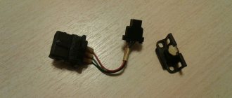
Color coding of terminals
Before installing the sensor, it is necessary to check the data with the instructions.
In practice, a standard system for marking the terminals of inductance sensors is used, which is followed by all manufacturers of sensitive devices without exception. However, before installing them, it is recommended to carefully monitor the polarity of the connection and be sure to check the instructions supplied with the products.
On the housings of all sensors there is a drawing with color markings of wires, if its dimensions allow it.
Standard notation:
- Blue always means negative power bus;
- brown color indicates the positive conductor;
- black corresponds to the sensor output;
- White is an additional output or input.
To clarify the last marking, it should be checked against the instructions supplied with the specific device.
Five-wire inductance sensors
Rice.
10. Connection diagram for a five-wire inductive sensor In a five-wire inductive sensor, two pins are used to supply voltage to the sensitive element of the sensor, in the example under consideration these are 1 and 3. Two pins 2 and 4 supply power to different loads, and control pin 5 allows you to select different operating modes and change the switching logic.
Errors
Errors in the process of converting diagnostic values affect the ability of induction sensors to provide reliable information. The main ones include the following.
Electromagnetic
This error is usually taken into account only as a random variable. As a rule, it occurs during the induction of EMF in the induction coil as a result of external influence by external magnetic fields. This occurs during the manufacturing process due to power electrical devices. They form magnetic fields, which subsequently forms an electromagnetic error.
From temperature
This error also acts as a random value, since the operation of a large number of elements of the induction sensor directly depends on temperature indicators, so this is a key quantity that is even taken into account in the design process of such equipment.
Magnetic elasticity
Typically, such an error can manifest itself as a consequence of instability in the deformation of the magnetic circuit of the device during the assembly of the sensor itself, as well as during deformation changes during operation. In addition, the effect of unstable electrical voltage on the magnetic circuit of the equipment causes a decrease in the quality of the transmitted signal at the output.
Deformation of elements
This error, as a rule, manifests itself as a result of the influence of the measuring force on the deformation value of the parts of the induction sensor, as well as under the influence of forces exerted on unstable deforming processes. In addition, it can be equally influenced by backlashes and gaps formed in the moving elements of the device’s structure.
Cables
Such an error usually manifests itself from an unstable resistance value, in the case of deformation of the wire itself and under the influence of temperature. Also, interference from external EMF fields in the cable can have a similar effect.
Aging
This error can manifest itself when the moving elements of the device itself wear out, as well as in the case of constantly changing magnetic properties of the magnetic circuit used. It is generally considered to be, strictly speaking, a random value. In the process of determining this error, the kinematics of the induction sensor design are taken into account, and during the design of such equipment, it is recommended to determine the maximum operating life only when operating in normal mode, so that wear does not have time to exceed the set value.
Advantages and disadvantages
Compared to other types of sensor devices, inductive sensors continue to occupy a significant niche, increasing the pace of implementation in various fields of industry and sectors of the national economy. This frequent use is explained by a number of significant advantages:
- high reliability due to simple design and absence of moving contacts;
- can operate both from a household network and from special generators, converters and other power sources;
- capable of providing significant output power - on the order of several tens of watts;
- characterized by high sensitivity in the measurement zone.
But, at the same time, there are also disadvantages of inductive sensors that do not allow their use everywhere. Among the most significant disadvantages are their bulky dimensions, which do not allow them to be mounted in any devices. Disadvantages also include the dependence of operating parameters on temperature and other factors that correct for accuracy.
Monitoring emergency situations using a tachometer
To count and indicate the number of actions per unit of time, as well as to issue a control signal when a given frequency setting is reached, we suggest using the TX1 RZShch tachometer .
In addition to constant monitoring of emergency situations (in machinery speed control systems), you receive:
- Universality/interchangeability of input ports;
- “Tracking” function that controls the output relay;
- Continuous and dynamic display;
- Programmable input signal frequency division factor;
- Rotation direction detection using two signals;
- Built-in power supply.
Device warranty - 24 months