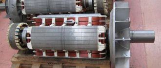
Modern industry, and everyday human activity as well, cannot be imagined without various kinds of electronic devices. They help us in everything, and some technological operations cannot be performed without them at all. These “helpers” include a capacitive sensor.
This is the name given to converters manufactured according to the parametric type. The measurement of a certain volume by such devices is carried out due to fluctuations in capacitance when some important parameters change. Simply put, the change in capacitance of the capacitor under the influence of some external factors is assessed.
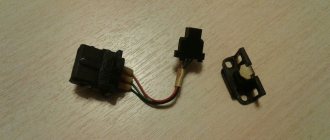
Operating principle of a capacitive sensor
That's what capacitive sensors are. The principle of their operation is not so complicated, but to understand it you need to know something. First, let's remember the principle of determining the capacitance of a capacitor. This action is expressed using the following formula:
С= εεₒS/δ.
Many people know this expression from a school physics course, but it wouldn’t hurt to refresh your memory and remember what each of the variables means:
- S is the area of the capacitor plate.
- Ε is the relative permeability of the dielectric material used in the design of the capacitor.
- εₒ is how physics usually denotes the dielectric constant of a vacuum.
- δ – this can indicate either the thickness of the dielectric plate, or the distance between several layers of material.
Thus, from the above formula it follows that it is easy to change the capacitance of the capacitor. It is enough to somehow influence the area of the plate of dielectric material, the distance between the plates, or directly the permeability of the material used in production. Accordingly, the choice of a specific value depends solely on the list of tasks that the designers set for the device.
Thus, you can even make a capacitive sensor with your own hands, since from a design point of view it is an ordinary flat or cylindrical capacitor, one of the plates of which constantly experiences controlled movement in space, which leads to a change in capacitance. One thing to remember is that the above formula is only valid if you completely neglect edge effects. We will talk more about this in the final part of our article.
You should know that this kind of electronic devices are intensively used to measure angular and linear movements of objects, calculate dimensions, applied work, humidity, concentration of the active substance and other characteristics. As for the constructive side of the issue, the mentioned instrumentation is made plane-parallel, in cylindrical housings, with pin electrodes, with a gasket made of dielectric material and without it at all.
This is how capacitive sensors function. The operating principle of some of them needs to be known in particular detail. In this article, we will provide several formulas that may be useful to you.
How does this meter work?
In essence, such a sensor is a capacitor. The operation of the meter and control of parameters are based on determining its characteristics. Therefore, it is quite appropriate to remember what a capacitor is.
About the capacitor, its characteristics
As is known, the capacitance of a capacitor is determined by the formula
С=Ɛ×Ɛ0×S/d
Where:
- Ɛ0—dielectric constant;
- Ɛ is the relative dielectric constant of the medium between the plates;
- d - gap between plates;
- S is the area of the plates.
There are three variables in this formula - the dielectric constant Ɛ, the area S of the capacitor plates and the gap between the plates d. Changing any of them will lead to a change in capacitance, and tracking fluctuations will allow you to monitor the characteristics of the environment or other parameter.
Operating principle of a capacitance meter
The simplest technical solution is to include a measuring sensor in the timing circuit of the generator. Without going into the intricacies of circuit design, we can say that the principle of operation of any capacitive sensor is in one way or another connected with changing the parameters of the generator. This occurs due to fluctuations in the capacitance of the capacitor, which leads to the generation of oscillations of a different frequency.
Thus, by monitoring its value at the output of the meter, it is possible to evaluate changes in the controlled parameter. Of course, in each specific case the circuit design may be different. It will largely depend on the parameter of the capacitor, which is influenced by the external environment.
This may be a change in the gap between the capacitor plates due to their approach or removal. Or when filling the tank with another medium, for example water, the value of the dielectric constant will change. Or the capacitor plates will be positioned differently relative to each other after external influences.
Any such impact will cause a change in the capacitance value of the capacitor, and therefore affect the operation of the circuit. For example, capacitive level sensors monitor the filling level of a tank or hopper. Knowing the relationship between the liquid level and the capacitance of the condenser, you can determine how full the tank is.
Although it should be noted that other methods of processing sensor signals can be used. There are quite a lot of them, the choice of one or another depends on specific conditions. The current level of electronics development makes it possible to obtain a processed signal in the form of a digital code.
Another method for measuring capacitance is using analog-to-digital converters. Microcontrollers can handle this task quite well. In this case, the measuring part of devices based on them is significantly simplified.
Formulas to describe the operating principle of some types of sensors
A level sensor with a possible change in the area of the dielectric plates can be quite easily described using the following equation:
C = εεₒаХ/δ.
In this case, “X” refers to the overlap length of the electrodes used. Accordingly, “a” denotes the width of the plates of the capacitor itself. It should be noted that such devices have found their application in a wide variety of industries, where they are used for precise measurement of angular quantities. The capacitance of the converter in this case is found using the following expression:
С= εεₒ(r₂- r₁)/2δ * (φₒ-φ).
In order to accurately measure sensitivity, a slightly different formula should be used:
K= εεₒ(r₂- r₁)/2δ.
Let's figure out what is meant by the variables that are part of these equations:
- r₁ is the internal radius of the capacitor plate;
- r₂ is the outer radius of the same plate;
- φ – currently measured (current) value of the overlap angle;
- φₒ is the initial value of the overlap angle.
Finally, let's look at the mathematical expression that describes the operating principle of a capacitance meter with a variable air gap:
С= εεₒS/(δₒ-Х).
It is not difficult to guess that δₒ refers to the primary gap, and the letter X denotes the amount of movement of the plate. Note! Since the static characteristics are not strictly linear, a level sensor of this type is usually used to measure extremely small movements, the value of which does not exceed 0.1δₒ. Naturally, these devices are in great demand in precision engineering, where even a small error can lead to quite serious problems.
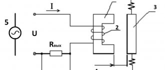
LC filters as the basis for capacitive measurement
One of the main problems of capacitance measurement is the presence of parasitic noise. Modification of a measuring device that includes a frequency-sensitive component can improve noise immunity. Additionally, a capacitor and an inductor are added to the sensor to form a resonant oscillatory circuit.
Where: a) filter circuit; b) its characteristics.
Although the LC filter architecture is simple, it has several significant advantages when integrated into a capacitance measurement device.
Firstly, the LC resonator provides excellent immunity to electromagnetic interference, and secondly, a noise source operating at certain frequencies can be filtered out by the LC resonator without the use of external circuits. This reduces the complexity of the system and reduces its cost.
Changing the capacitance of the LC circuit will lead to a shift in the resonant frequency. This principle is used by the FDC2214 in a capacitive-to-digital converter that measures the oscillation frequency of the LC filter. The device outputs a digital value proportional to this frequency. The measurement data can be converted into equivalent capacitance to the downstream microcontroller.
Where can they be used?
The areas of their possible application are extremely diverse. Thus, in almost all industries you can find operations that are controlled by these devices. They are used to control the filling of various tanks, and their contents can be liquid, bulk or gaseous (gas sensor).
Their prevalence in industry and normal human production activities is higher, the more reliable and simple the design of such devices. Based on the combination of these characteristics, they are so good that they can be used even in the incredibly aggressive conditions of the holds of oil tankers.
In addition, the capacitive sensor can be used as a limit switch on a conveyor line or machine in a production workshop. It is also necessary for the most accurate positioning of various mechanisms.
Areas of application
These devices are used for the following purposes:
- For detection of plastics and other insulators.
- In alarm systems, when establishing the fact of movement within a controlled area.
- As a component of car security devices.
- To determine the surface cleanliness of materials after machining.
- For the purpose of determining the level of liquid or gaseous working media in closed tanks.
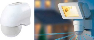
- When installing systems for automatically turning on/off lamps.
In all cases, capacitive sensors are subject to mandatory calibration in factory or other specialized conditions.
Proximity sensors
But nowadays, proximity sensors, which are made according to exactly the same principle, are in particular demand. The range of their use is even wider. This is due to the cheap cost of the devices and the ability to work in almost all types of industry. However, there are typical industries where devices of this type are most in demand:
- Control over the filling of liquid in transparent containers made of plastic or glass.
- They perform a similar function in the production of food products (including children’s), where the finished product is packaged in containers made of transparent materials. The operation of such instrumentation as a capacitive fuel sensor is based on the same principle.
- To control hazardous areas where the winding wire may break.
- Inspection of similar places where the conveyor belt may be damaged.
- Piece control of the type of product being manufactured (counting of cans, bottles, packages).
It is not surprising that these electronic devices are the most common type of sensor in precision engineering, energy and many other industries.
Automation using level sensors
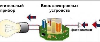
Photo relays and principles of their operation
We have ready-made solutions for automation and dispatch of water utilities, as well as for monitoring and control of sewage pumping stations, enterprise collectors and control of the discharge of non-cooled water from thermal power plants. The systems are autonomous and have an archive.
We offer centralized monitoring and control systems for wells and the operation of pumping mechanisms. The use of our instruments and systems allows the user to obtain reliable data on well production, flow rate, level, pressure and other parameters.
We supply secure instrumentation. Including explosion-proof liquid level sensors and intrinsically safe transmitters and relays for a wide range of industries. For example, our devices are capable of operating at air temperatures below – 35*C or at a hazardous oil refining production site.
Our customers include almost all regions of Russia, for example, the cities: St. Petersburg, Moscow, Novy Urengoy, Murmansk, Bryansk, Nizhny Novgorod, Veliky Novgorod, Yekaterinburg, Golitsyno, Khanty-Mansiysk, Arkhangelsk, Stary Oskol, Cherkessk.
Each liquid level sensor presented in our assortment has proper specifications and information about the principles of operation and recommendations for use, which you can familiarize yourself with before placing an order. This will help you make your choice and get acquainted with the capabilities of each type of automation. If you find it difficult to choose and want to obtain broader information on specific types of sensors, converters and liquid level switches, our qualified specialists will provide you with the necessary advice.
Poltraf CIS supplies to St. Petersburg, Moscow, as well as to other regions of Russia and the CIS countries.
Water level monitoring using hydrostatic liquid level sensors
It is difficult to imagine modern industry without automation and control systems, a significant part of which is occupied by sensors, converters and liquid level relays. They are designed for installation in various tanks to determine the level of liquid media. This type of sensors is mainly used in the food, chemical and pharmaceutical industries, as well as in the production of industrial and household equipment (washing machines, dishwashers, filtration and water supply systems, etc.).
Depending on the principle of operation, sensors, transducers and level relays for liquid media are classified into two types: contact (float type) and non-contact (electromagnetic, fiber-optic, capacitive, frequency, hydrostatic and ultrasonic).
Selection of level sensors (level gauges)
In the product range you can buy sensors, transducers and water level switches for measuring both one given level and for continuously monitoring changes in the water level in the tank. This makes it possible to automate complex technological systems and significantly simplify the production process or equipment operation.
The accuracy of the measurements, as well as the reliability and cost of the automation, directly depend on the type of sensor, as well as its operating conditions. For example, capacitive liquid level meters are used in particularly difficult conditions, for which they are additionally equipped with protection systems against short circuits and polarity reversal when connecting power.
Piezoelectric liquid level sensors can be used to measure all types of liquids, including the possibility of steam or foam formation. The most inexpensive types of sensors are ultrasonic or radar liquid sensors, which are also highly reliable and have a housing protected from external influences. However, the measurement accuracy of such a sensor can be about +/− 3 mm.
In comparison, fiber optic liquid level sensors, which are much more expensive than capacitive ones, provide an accuracy of +/− 0.5 mm. In addition, optical sensors allow measurements in both clean and turbid liquids. Sensors, converters and liquid level relays can also be domestic or imported, which will also determine their cost.
Inclinometers
Devices that have become relatively common only in recent years are small-sized capacitive inclinometers that provide the transmission of an electrical output signal, the magnitude of which is directly proportional to the angle of inclination of the sensor used.
The most common main areas of use of these devices: platform leveling systems, determination of the amount of deflection and technical deformation of various types of support beams, as well as precise control of the slope of automobile and railway tracks at the stage of their construction.
In addition, with the help of such devices, the roll of heavy-duty vehicles and other vehicles, lifts and industrial excavators is determined, as well as the degree of angular movement in relation to especially large agricultural and industrial machines.
Capacitive fuel level sensors are very important in the oil industry. They are even used on supertankers, which transport tens and hundreds of thousands of tons of refined petroleum products in one voyage. These devices are extremely effective even in conditions of the formation of extremely abundant condensation and a high degree of dust in the production area (the same gas sensor).
They also find their application in measuring absolute and relative pressure levels, as well as the thickness of dielectric material, which is extremely important in almost all industries where truly powerful capacitors are used.
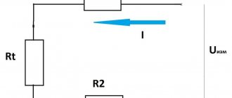
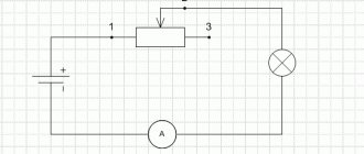
Do-it-yourself diagrams
To organize touch control, a capacitive sensor can be easily created using a base, a capacitor and a pair of resistors. When you touch the wires, an electrical charge accumulates, by adjusting the amount of which you can change the charging/discharging time. This circuit can be used to control a table lamp or other lamp. The circuit must contain an electronic comparator that will compare the charging time of the capacitor with the reference (threshold) value and issue the corresponding control signal.
Touch-controlled electronic circuits are more interactive for the user than traditional ones and can therefore be effectively used for power switching purposes. The capacitance of the capacitor determines the level of sensitivity: as the capacitance increases, the sensitivity increases, but more power and shorter response time are required to power the device. For indication, you can use a regular LED.
Main advantages of capacitive sensors
It should be noted that the capacitive sensor has many advantages when compared with similar devices that are made according to slightly different principles. Let's list the main advantages of these instrumentation systems:
- They are extremely simple to make. In addition, the simplest and cheapest materials can be used in their production. Even capacitive fuel level sensors used at important oil industry facilities have extremely modest dimensions and have the lowest possible level of electrical energy consumption. With all these characteristics, they are distinguished by an excellent level of sensitivity, which is often unattainable even for more expensive devices.
- In principle, you can make a capacitive sensor with your own hands, using any more or less reliable and high-quality industrial capacitor as its basis.
- They do not have contacts (one current collector is very rarely used), which has an extremely beneficial effect on working in conditions of high dust and humidity in the room.
- The service life is extremely long; the device manages to “recoup” its low cost many times over. Accordingly, a capacitive sensor (the price of which is in the range of 1200-1700 rubles) is an extremely profitable purchase.
- Surprisingly little effort is required to move the moving part of the device.
- The device is very easily combined with almost all categories of equipment that is used in industrial activities.
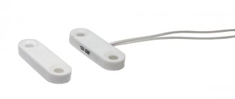
Connection diagram for reed switch water level sensor
Reed switches are low power devices and are unable to switch high currents, so they cannot be used directly to turn a pump off and on. They are usually involved in the low-voltage switching circuit for the operation of a high-power pump relay located in the control cabinet.
The figure shows the simplest circuit with a sensor that controls the drainage pump depending on the water level during pumping, consisting of two reed switches SV1 and SV2.
When the liquid reaches the upper level, the magnet with the float turns on the upper reed switch SV1 and voltage is applied to the relay coil P1. Its contacts close, a parallel connection to the reed switch occurs and the relay is self-capturing.
Voltage is supplied to the coil of a powerful relay in the power supply circuit of the pump, its contacts close and the electric pump begins to work. When the water level drops and the float with the magnet of the lower reed switch SV2 reaches it, it turns on and a positive potential is also applied to the relay coil P1 on the other side, the current stops flowing and relay P1 turns off. This causes a lack of current in the coil of power relay P2 and, as a result, the supply voltage to the electric pump stops.
Rice. 6 Float vertical water level sensors
A similar pump control circuit, placed in the control cabinet, can be used when monitoring the level in a tank with liquid, if the reed switches are swapped, that is, SV2 will be at the top and turn off the pump, and SV1 in the depths of the water tank will turn it on.
Level sensors can be used in everyday life to automate the process when filling large containers with water using electric water pumps. The easiest types of reed switches to install and operate are those produced by industry in the form of vertical floats on rods and horizontal structures.
To automate many production processes, it is necessary to monitor the water level in the tank; the measurement is carried out using a special sensor that gives a signal when the process medium reaches a certain level. It is impossible to do without level meters in everyday life; a striking example of this is the shut-off valve of a toilet cistern or an automatic system for shutting off a well pump. Let's look at the different types of level sensors, their design and operating principle. This information will be useful when choosing a device for a specific task or making a sensor yourself.
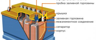
Design and principle of operation
The design of measuring devices of this type is determined by the following parameters:
- Functionality, depending on this device, is usually divided into alarms and level meters. The former monitor a specific tank filling point (minimum or maximum), while the latter continuously monitor the level.
- The operating principle can be based on: hydrostatics, electrical conductivity, magnetism, optics, acoustics, etc. Actually, this is the main parameter that determines the scope of application.
- Measuring method (contact or non-contact).
In addition, the design features are determined by the nature of the technological environment. It is one thing to measure the height of drinking water in a tank, and another to check the filling of industrial wastewater tanks. In the latter case, appropriate protection is necessary.
Negative points
Unfortunately, each capacitive sensor has certain disadvantages that, to one degree or another, complicate the widespread use of this type of equipment. Let's list them in more detail:
- The conversion (i.e. transmission) coefficient is relatively low.
- The small size and simplicity of design contribute to the fact that quite high requirements are put forward for the quality of shielding of devices.
- A good capacitive level sensor (and other similar measuring instruments) can only operate effectively at frequencies much higher than the standard 50 Hz.
Measuring without touching
Capacitive sensing is not a capacitive sensor (a similar technology optimized to perform the functions of a digital switch)! A capacitive touch system uses multiple channels in a row and column arrangement (like a touch screen on a phone or tablet). The touch screen requires direct contact and operates over a very short range - in most cases a few millimeters.
Unlike a similar system - a touch screen, a capacitive sensor is an analog system and operates at a distance of up to 70 cm. It has much greater sensitivity and accuracy, since the capacitance changes only a few picofarads.
Important Notes
However, everything is not so bad.
Many manufacturers achieve excellent sensor shielding performance by making minimal changes to their design. As for the frequency of use, in practice they show excellent results at the widely used industrial value of 400 Hz. We have already talked about the validity of the basic formula only if the edge effect is ignored. But it is useful to know that it can really have a negative effect only if the distance between the dielectric plates is comparable to their own dimensions. In addition, the negative effect can be largely neutralized by simply using a protective ring. In this case, the boundaries of the effect’s influence can be moved far beyond the limits of the plates used.
Let us note once again that the same pressure sensors are distinguished by their remarkable simplicity, which makes it possible to create surprisingly stable, durable and cheap structures. If you choose the right geometric dimensions of the dielectric used, then you don’t have to worry too much about the materials used in the production of such a capacitor.
Thus, by choosing the right grade of metal for the manufacture of the sensor body, you can practically neglect even strong temperature fluctuations, which could lead to a change in the capacitance of the device and the inadequacy of its readings. Of course, this does not at all negate the need to carefully isolate pressure sensors and other similar indicators from aggressive environmental factors. Despite their simplicity, high humidity and increased levels of radiation can have an extremely negative impact on the reliability of the device.
Scope of application of water level sensors
Rice. 1 Operating principle of a float level sensor (RPL)
- A large storage tank for water may also be required for water supply at home if the flow rate of the water intake tank is very small or the performance of the pump itself cannot ensure water consumption corresponding to the required level. In this case, liquid level control devices for automatic operation of the water supply system are also necessary.
- The liquid level control system can also be used when working with devices that do not have protection against dry running of the well pump, a water pressure sensor or a float switch when pumping groundwater from basements and rooms with a level below the ground surface.
Sensor classification
The methods of their production used in industry make it possible to divide all manufactured types of sensors into two large groups: single-capacitive and double-capacitive. The latter variety is divided into differential and semi-differential. Let's look at them in more detail.
Single-capacity device. In this case, the circuits of capacitive sensors are extremely simple, since their main part is the most common capacitor with variable capacitance. Unfortunately, even slightly increased humidity and temperature have a very noticeable effect on the accuracy of the readings. Because of this, various sensor malfunctions often occur. To level out the magnitude of such errors, it is necessary to use differentiated designs.
Dual capacitance sensor. Actually, it is this differentiated structure. Very often you can find a capacitive level sensor made exactly according to this design. These devices are free from the main disadvantages of the previous model, but have their own weaknesses. Their most significant disadvantage is the need to use two or three shielded wires between the device itself and the surface, since only in this way can the so-called parasitic capacitances be suppressed.
However, in this case it is easy to ignore the rather complex circuits of capacitive sensors, since in return you get an extremely accurate and sensitive device.
Popular models
Autonics proximity sensors: inductive and capacitive
The modern market offers many models of alarms. The most popular of them:
- DE-1 (capacitive sensor). Most often, this alarm is used in aggressive environments in the chemical and metallurgical industries. It allows you to control the temperature and level of bulk and liquid substances. Often used in emergency protection installations.
- ESU-1 (electronic level switch). The body of this model is made of high quality steel and fluoroplastic. Most often, ESU-1 is installed in explosive and aggressive environments. The power source is located outside the process environment. The sensor measures the level of oil, alcohol and water. The power supply is made of durable aluminum alloy.
- RU-305 (level relay). This device is designed to monitor the condition of liquid media. Its body is made of special material and can easily withstand temperatures from -50 to +50 degrees Celsius. However, RU-305 must not be used in aggressive chemical environments. Among the disadvantages of this level gauge, consumers note only that it works only in one position, without tilt. Level measurement is carried out by moving a magnet with a float and triggering a reed switch. Measurements have an accuracy of no more than 5 mm.
- SU-100 (level alarm). Sensor for measuring the level of bulk and liquid substances. The SU-100 design contains an electromagnetic relay.
- Rosemount 5600 This radar level sensor allows non-contact measurement of any type of substance. To achieve the most accurate readings, the level gauge must be installed correctly. The device's reading accuracy may be degraded by exposure to electromagnetic radiation. The housing has an explosion-proof design and a display that displays all the necessary information. The Rosemount 5600 can be used to measure tank temperatures. To fully evaluate the capabilities of this equipment, it requires qualified adjustment taking into account the diameter of the pipeline, the length of the level gauge and the distance between the level and the reference point.
It is advisable to purchase complex models only for industrial use. The simplest versions of level meters are suitable for domestic purposes.
Specifics of sensor design
In many cases (from a design point of view), the creation of such devices is quite problematic.
This is especially true when it is necessary to create a sensor with a variable level of capacitance. However, practice shows that many problems can be almost completely solved by precise calibration and high characteristics of the materials used in production. Most often, manufacturers of dual-capacitance sensors have to face these difficulties. In general, the specificity of this type of measuring instruments lies in the fact that they can be represented as a dimensionless ratio of two physical quantities (capacities), which have a precise physical expression and meaning. So we can safely call them “attitude sensors.” The advantage of these devices (a huge plus!) is that they may not have any reference measures in their design, which greatly increases their reliability in truly extreme situations and conditions.
Introduction
There are many types of proximity sensors used in different applications. We use capacitive proximity sensors to detect any type of object without contact. They perceive objects by measuring the change in an electrical property, capacitance .
This article aims to provide a detailed guide to capacitive proximity sensors and their applications.
Characteristics of linear displacement sensors
All non-electrical quantities that often need to be controlled in industrial environments are extremely diverse and multifaceted. A significant part of the measures that are subject to strict control are angular and even linear movements of various kinds of surfaces in space. If you use a capacitor that has an absolutely uniform electric field in the working gap, then it is not so difficult to make electronic sensors of the following two types:
- In which the area of the electrodes will be variable.
- Those that have a variable gap between these electrodes.
It is not difficult to understand that the first type is most suitable for recording really large movements, while with the help of the second type one can even notice such body movements in space, the magnitude of which is only a few microns!
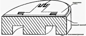
How a capacitor becomes a sensor
In this case, cause and effect are reversed. When voltage is applied to a conductor, an electric field is generated at each surface. In a capacitive sensor, the measuring voltage is applied to the sensitive area of the probe, and for accurate measurements, the electric field from the probed area must be contained precisely in the space between the probe and the target.
Unlike a conventional capacitor, when capacitive sensors operate, the electric field can spread to other objects (or to individual areas of them). The result will be that the system will recognize such a composite field as several targets. To prevent this from happening, the back and sides of the sensitive area are surrounded by another conductor, which is maintained at the same voltage as the sensitive area itself.
When a reference supply voltage is applied, a separate circuit supplies exactly the same voltage to the sensor protection. If there is no difference in voltage values between the sensitive zone and the protective zone, there is no electric field between them. Thus, the original signal can only come from the unprotected edge of the primary circuit.
Unlike a capacitor, the action of a capacitive sensor will be affected by the density of the object's material, since this disrupts the uniformity of the generated electric field.
Sensors for detecting angular movements
In general, in design and purpose they are almost completely identical to the type we just considered. The similarity is also evident in the fact that sensors with a variable area of electrodes should also be used for large measurements, and with a variable distance between the electrodes themselves - for small ones. As a rule, such devices are made multi-sectional, with the possibility of changing the area of the capacitor plates.
To achieve this, the first electrode is attached to a movable shaft, when rotated it changes its position relative to the second, which ensures a change in the overlap area of the dielectric plates in the capacitor. Naturally, a change in capacitance is recorded in this case.
Water level sensor assembly
- Attach the Reed switches to the plastic clamp with hot glue, having previously determined the required distance experimentally. Treat the connection with silicone;
- Place the finished bracelet on the coupling. The length of the float holder determines the actuation stroke of the device;
- The float must be heated with a hairdryer and quickly placed on the coupling, then glued and connected with rivets. The clamp should rotate easily around the coupling with reed switches;
- Install the plugs on the float and attach it to the profile with rivets;
- A neodymium magnet is also attached, which should be within the operating distance of the reed switches;
- Drill a hole in the coupling and install the float stopper;
- Place the assembled structure on the pipe and connect the plug and LED indicator.
I am attaching photos of the assembly:
conclusions
So we looked at the main characteristics of devices of this level, learned about their areas of application, design features, operating principles and possible technical solutions.
As you can understand from the article, the prevalence of capacitive sensors and their extremely high popularity are based on the very attractive price of such devices and long service life even in difficult environmental conditions. All this is possible due to the fact that, from a design point of view, all these meters are just standard capacitors, which are characterized by a somewhat unusual way of using them. However, you can find out for yourself by taking another look at the mathematical formulas, which in general terms reflect the operating principles of instrumentation.
Operation block diagram
While not directly directional, a capacitive sensor measures some capacitance from objects that are constantly present in the environment. Therefore, unknown objects are detected by him as an increase in this background capacity. It is significantly larger than the capacity of the object and is constantly changing in size. Therefore, the devices in question are used to detect changes in the environment rather than to detect the absolute presence or absence of an unknown object.
As the target approaches the probe, the amount of electrical charge or capacitance changes, which is recorded by the electronic part of the sensor. The result can be displayed on the screen or touch panel.
To make measurements, the device is connected to a printed circuit board with a touch controller. The sensors are equipped with control buttons. Which can be used to operate several probes at the same time.
Touch screens use sensors with electrodes arranged in rows and columns. They are either on opposite sides of the main panel, or on separate panels that are separated by dielectric elements. The controller cycles between the different probes to first determine which row is being touched (Y direction) and then which column is being touched (X direction). Probes are often made of transparent plastic, which increases the information content of the measurement result.
Hysteresis
Hysteresis is the difference between the on distance and the off distance. It defines a zone A not a line for the perception of an object.
Hysteresis causes the output to "lock" even when an object moves away from or toward the sensor field. This prevents the effect of "blinking" (the output turning on and off repeatedly) if the object is at the edge of the detection range.
Hysteresis is an independent parameter. This is a percentage of the rated sensing distance. For example, a sensor with a nominal sensing distance of 20 mm may have a maximum hysteresis of 15%. This is about 3mm of response range. It can vary from sensor to sensor, even for the same model.
There are several factors that can affect hysteresis:
- Ambient temperature and local temperature sensor
- Atmosphere pressure
- Relative humidity
- Mechanical stress of the sensor body
- Sensitivity correlation - higher sensitivity, greater hysteresis