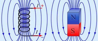
Good day to all. In the last article I talked about the magnetic field and dwelled a little on its parameters. This article continues the topic of the magnetic field and is devoted to such a parameter as magnetic induction. To simplify the topic, I will talk about the magnetic field in a vacuum, since different substances have different magnetic properties, and as a result, it is necessary to take their properties into account.
To assemble a radio-electronic device, you can pre-make a DIY KIT kit using the link.
Biot–Savart–Laplace law
As a result of studying the magnetic fields created by electric current, researchers came to the following conclusions:
- magnetic induction created by electric current is proportional to the strength of the current;
- magnetic induction depends on the shape and size of the conductor through which the electric current flows;
- magnetic induction at any point in the magnetic field depends on the location of this point in relation to the current-carrying conductor.
The French scientists Biot and Savard, who came to such conclusions, turned to the great mathematician P. Laplace to generalize and derive the basic law of magnetic induction. He hypothesized that the induction at any point of the magnetic field created by a current-carrying conductor can be represented as the sum of the magnetic inductions of elementary magnetic fields that are created by an elementary section of a current-carrying conductor. This hypothesis became the law of magnetic induction, called the Biot-Savart-Laplace law . To consider this law, let us depict a current-carrying conductor and the magnetic induction it creates
Magnetic induction dB created by an elementary section of a conductor dl.
Then the magnetic induction dB of the elementary magnetic field, which is created by a section of the conductor dl , with current I at an arbitrary point P will be determined by the following expression
where I is the current flowing through the conductor,
r is the radius vector drawn from the conductor element to the magnetic field point,
dl is the minimum conductor element that creates induction dB,
k – proportionality coefficient, depending on the reference system, in SI k = μ0/(4π)
Since it is a cross product, then the final expression for the elementary magnetic induction will look like this
Thus, this expression allows us to find the magnetic induction of the magnetic field, which is created by a conductor with a current of arbitrary shape and size by integrating the right side of the expression
where the symbol l indicates that integration occurs along the entire length of the conductor.
Magnetism
Table of contents:
A magnetic field is a form of matter surrounding moving electric charges. A magnetic field surrounds current-carrying conductors.
The strength characteristic of a magnetic field is magnetic induction.
Magnetic induction is a quantity equal to the ratio of the maximum moment of force rotating a circuit with current in a magnetic field to the current strength in this circuit and its area:
Another definition of magnetic induction: magnetic induction is a quantity equal to the ratio of the maximum force acting on a current-carrying conductor in a magnetic field to the current strength in it and the length of this conductor in a magnetic field:
Magnetic induction is a vector quantity. The magnetic induction vector coincides in direction with the positive normal to the contour plane. Behind
the direction of the positive normal n is the direction of translational movement of the right screw (gimlet) when its head rotates along the current in the circuit (Fig. 208).
The right screw can be your right hand. If you curl the four fingers of your right hand in the direction of the current in the circuit, then the thumb, set at 90°, will show the direction of the positive normal and the magnetic induction vector.
The SI unit of magnetic induction is tesla (T).
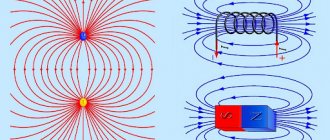
The magnetic field is depicted graphically using magnetic field lines or magnetic induction vector lines.
There are no magnetic charges in nature, so the lines of the magnetic induction vector are always closed.
The magnetic field is vortex, in contrast to the potential electrostatic field, the lines of which are always open, since they begin and end on electric charges. The lines of the magnetic induction vector cover current-carrying conductors. The lines of the magnetic induction vector of the direct current field are concentric circles with the center on the current-carrying conductor (Fig. 209). Their direction can be determined using the right screw (or using your right hand: if you point your right thumb in the direction of the current in the conductor, then the four curled fingers will show the direction of the magnetic induction line). As you move away from the current-carrying conductor, the magnetic field induction of this current decreases.
A magnetic field , at each point of which the magnetic induction vector is the same, is called uniform. Magnetic induction lines of a uniform field are straight lines located at the same distance from each other. The denser they are, the greater the magnetic induction.
An example of a uniform magnetic field is the magnetic field inside a long solenoid - a coil with current (Fig. 210).
Magnetic induction lines leave the north pole N and enter its south pole S.
The magnetic field of a strip magnet (Fig. 211) is greatest at its poles, and in the center its magnetic induction is zero.
If a circuit with current is introduced into a uniform field, placing its plane parallel to the lines of magnetic induction, then on the sides of the circuit perpendicular to the lines of magnetic induction a pair of Ampere forces will act, which will create a maximum torque equal to the product of the magnetic field induction and the current strength in it and its area:
If the contour plane is located at an angle to the lines of the induction vector of a uniform magnetic field, then the moment of force is determined by the formula
Here is the angle between the magnetic field induction vector and the normal to the plane of the frame.
The moment of forces rotating a circuit with current in a uniform magnetic field is equal to the product of the induction of this field, the current strength in the circuit, the area of the circuit and the sine of the angle between the vectors of magnetic induction and the normal to the plane of the circuit.
If the plane of the contour is perpendicular to the lines of the magnetic induction vector, then the torque of the forces is equal to 0, and the Ampere forces act in the plane of the contour, deforming it.
The direction of the Ampere force can be determined by the left hand rule: if the palm of the left hand is positioned so that the magnetic lines enter the palm, and four extended fingers are directed along the current in the conductor, then the thumb, set 90 degrees apart, will show the direction of the Ampere force acting on this conductor in a given magnetic field (Fig. 212).
If a current-carrying conductor is placed parallel to the magnetic lines, then the Ampere force will not act on it.
Ampere power
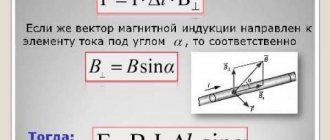
The magnitude of the Ampere force is determined by Ampere's law: the force F acting on a conductor with current in a uniform magnetic field is equal to the product of the magnetic induction of this field B, the current strength in the conductor I, the length of the conductor in the magnetic field I and the sine of the angle a between the direction of the magnetic field and the direction current in the conductor:
The force with which a magnetic field acts on a charge moving in it is called the Lorentz force.
Lorentz force
The Lorentz force acting on a charge q moving in a uniform magnetic field is equal to the product of the induction of this field B by the charge, by the speed of its movement v and by the sine of the angle between the direction of the magnetic field and the direction of motion of the charge
The direction of the Lorentz force can also be determined by the left-hand rule: if the palm of the left hand is positioned so that the magnetic lines enter it, and the four extended fingers are directed in the direction of movement of the positive charge (or against the direction of movement of the negative charge), then the thumb placed on 90″, will show the direction of the Lorentz force.
A charged particle flying into a uniform magnetic field perpendicular to its magnetic lines moves uniformly along a circle enclosing the magnetic lines.
In this case, the Lorentz force is directed radially towards the center of the circle.
In Fig. 213 a positively charged particle with a charge q, flying in the direction shown by the vector v into a uniform magnetic field of induction B, directed behind the drawing, moves around the magnetic lines counterclockwise.
If a charged particle flies into a magnetic field at an angle to the magnetic lines, then it will move along a helical line (Fig. 214), rotating in a circle with a linear speed equal to the normal component of the velocity vector usin a, and at the same time moving
uniformly along the lines of the magnetic field induction vector with the tangential component vcos a of the velocity vector.
The distance x that it flies along the magnetic line in one revolution is called the pitch of the screw. Since the particle moves along the magnetic line at a constant speed u, the propeller pitch is equal to
Here T is the period, i.e. the time of one revolution of a particle around magnetic lines.
The Lorentz force is always perpendicular to the velocity vector and, therefore, to the vector of movement of the charge, therefore it does not do the work of moving the charge in a magnetic field, as a result of which the kinetic energy of the charge moving in the magnetic field under the influence of the Lorentz force does not change.
If a charged particle moves simultaneously in electric and magnetic fields (i.e., in an electromagnetic field), then it is acted upon by the generalized Lorentz force, equal to the vector sum of the Lorentz force acting on it from the magnetic field and the Coulomb force acting on it from the electric field. fields.
Let there be a certain area S in a uniform magnetic field due to induction (Fig. 215).
The magnetic flux Ф created by a uniform magnetic field through a certain area is equal to the product of the induction of this magnetic field B by the value of the area S and by the cosine of the angle a between the magnetic induction vector and the normal to the area.
If area S is located perpendicular to the magnetic lines of a uniform field, then the magnetic flux crossing it is maximum:
If the site S is located parallel to the magnetic lines, then they do not intersect it, therefore the magnetic flux through the site in this case is zero.
Magnetic flux
Magnetic flux is a scalar algebraic quantity, i.e. it can be positive or negative, since the cosine of an angle can be greater or less than zero.
If a magnetic flux crosses a closed surface (imagine it in the form of an inflated balloon), then, since all magnetic lines are continuous and close on themselves, the number of magnetic lines entering this surface, creating a negative flux, will be equal to the number of magnetic lines leaving, creating numerically the same in magnitude, but positive flow. Therefore, the total flux of the magnetic induction vector through a closed surface is zero. This important property of the magnetic field indicates the absence of magnetic charges in nature and the vortex nature of the magnetic field.
The SI unit of magnetic flux is weber (Wb).
When the magnetic flux through the area bounded by a conducting circuit changes, an induced current appears in this circuit.
Lenz's rule: the induced current is always directed in such a way that with its magnetic field it counteracts the change in the magnetic flux that caused this current.
Let's turn to Fig. 216, a). When the magnetic flux through the circuit, created by the magnetic field induction external to the circuit, increases, the induced current in the circuit is directed so that its magnetic field by induction (in Fig. 216, a) it is depicted by dashed arrows) is antidirectional to the external magnetic field, counteracting increase in magnetic flux. Note that the direction of the current is related to the direction of its magnetic field by the rule of the right screw - gimlet. When the magnetic flux created by the external magnetic field by induction decreases (Fig. 216, b), the induction current in the circuit changes its direction to the opposite and at the same time its magnetic field turns out to be co-directed with the external field. Now the magnetic field of the induced current counteracts the decrease in magnetic flux created by the external magnetic field through the circuit, maintaining it.
The phenomenon of the appearance of an induced current in a circuit when the magnetic flux crossing this circuit changes is called electromagnetic induction. According to Ohm's law, the strength of the induced current is directly proportional to the induced emf and inversely proportional to the resistance of circuit B:
Faraday's law
Faraday's law for electromagnetic induction: The emf of electromagnetic induction that occurs in a circuit with any change in the magnetic flux crossing this circuit is equal to the rate of change of the magnetic flux, taken with a minus sign,
Here is the induced emf in the circuit, is the rate of change of the magnetic flux crossing the circuit, N is the number of turns in the circuit (dimensionless).
This formula is valid when the magnetic flux changes monotonically, i.e. when over equal periods of time it changes by the same amount and the induced emf is constant. If the magnetic flux changes arbitrarily, either increasing or decreasing, which happens when the circuit rotates in a magnetic field, then it is impossible to use this formula to determine the instantaneous value of the induced emf; it can only be used to determine the average value of the induced emf.
With an arbitrary change in the magnetic flux through the circuit, the induction emf is equal to the first derivative of the magnetic flux with respect to time, taken with a minus sign:
Here is the first derivative of the magnetic flux with respect to time.
The minus sign in these formulas is explained by Lenz's rule.
If the circuit crossed by an alternating magnetic flux contains not one, but N turns, then the induced emf in it will be N times greater than in one turn. In this case, the previous formulas will take the form:
The induced emf arising in a conductor moving translationally in a uniform magnetic field at an angle to the magnetic lines is equal to the product of the induction of this field by the speed of the conductor, by its length in this field and by the sine of the angle between the magnetic induction vector and the velocity vector of the conductor:
Induction emf that occurs in a circuit rotating uniformly in a uniform magnetic field is equal to the product of the angular velocity of the circuit by the induction B of the magnetic field, by the area of the circuit S and by the sine of the angle a between the magnetic induction vector and the normal to the plane of the circuit:
In the case when the contour plane is parallel to the magnetic lines, the angle . Then the induced emf in the circuit will be maximum.
If the circuit contains N turns, then the induced emf in it is N times greater than in one turn:
The phenomenon of the occurrence of induced emf and induced current in a circuit due to a change in the current flowing in this circuit is called the phenomenon of self-induction.
The magnetic flux F through a coil (or a circuit of any other shape) is directly proportional to the current strength in it, i.e. There is a directly proportional relationship between these quantities:
Here L is the proportionality coefficient between the current and the associated magnetic flux. It is called the loop's self-inductance coefficient or its inductance. The amount of inductance depends on the shape and size of the circuit itself, as well as on the magnetic properties of the medium, and is constant for a given circuit. Loop inductance is a positive scalar quantity. It does not depend on the presence or absence of current in it. The inductance of factory-made coils is indicated in their passport.
The SI unit of inductance is henry (H).
Self-induction emf, which occurs in a circuit when the current in it changes, is directly proportional to the rate of change of current in the circuit, taken with a minus sign:
Here is the rate of change of current, i.e. change in current strength per unit time.
If the current in the circuit changes arbitrarily, then it is impossible to use this formula to determine the instantaneous self-induction EMF; it can only be used to determine the average value of the self-induction EMF over time. To determine the instantaneous value of the self-induction emf in this case, one must use the formula
The instantaneous self-induction EMF is directly proportional to the first derivative of the current strength with respect to time, taken with a minus sign.
A magnetic field, like any force field, has energy.
The energy of the magnetic field of the coil carrying the solenoid current is equal to half the product of the inductance of this solenoid and the square of the current in it:
Since the magnetic field is diffuse throughout space, in order to characterize its energy properties, a value is introduced equal to the energy of the magnetic field per unit volume of space occupied by this field. This quantity is called the volumetric magnetic field energy density.
The volumetric energy density of the magnetic field is equal to the ratio of the energy of the magnetic field to the volume V of the space occupied by it:
The volumetric energy density of a magnetic field is directly proportional to the square of the magnetic induction of this field and inversely proportional to the relative magnetic permeability of the environment:
This theory is from the page for detailed solutions to problems in physics, there is a theory and detailed solutions to problems on all topics in physics:
Physics problems with solutions
You might find these pages useful:
| Electrostatics basic concepts, laws and formulas |
| DC laws: basic formulas |
| Mechanical vibrations in physics: basic formulas and laws |
| Electromagnetic oscillations in physics: basic formulas |
Magnetic induction of a straight conductor
As you know, the simplest magnetic field creates a straight conductor through which electric current flows. As I already said in the previous article, the lines of force of a given magnetic field are concentric circles located around the conductor.
Magnetic induction of a magnetic field created by a straight conductor carrying current.
To determine the magnetic induction B of a straight wire at point P , we introduce some notation. Since point P is located at a distance b from the wire, the distance from any point on the wire to point P is determined as r = b/sinα. Then the shortest conductor length dl can be calculated from the following expression
As a result, the Biot–Savart–Laplace law for a straight wire of infinite length will have the form
where I is the current flowing through the wire,
b is the distance from the center of the wire to the point at which the magnetic induction is calculated.
Now we simply integrate the resulting expression over dα in the range from 0 to π.
Thus, the final expression for the magnetic induction of a straight wire of infinite length will have the form
where μ0 is the magnetic constant, μ0 = 4π•10-7 H/m,
I – current flowing through the wire,
b is the distance from the center of the conductor to the point at which the induction is measured.
Application of magnetic force
The magnetic deflection of electrons in a cathode ray tube is one example of the practical application of magnetic force. A cathode ray tube is a vacuum tube with an electron gun at one end and a phosphorescent screen at the other end. The electrons are ejected from the electron gun at high speed and impact the screen, where a spot of light is produced when exposed to the phosphor.
Because electrons have a charge, they can be deflected in flight by electrical or magnetic force. The deflection control allows you to move the spot of light across the screen.
"Old" type TVs use this magnetic deflection principle to form images by quickly scanning a spot.
Magnetic induction of the ring
The induction of a straight wire has a small value and decreases with distance from the conductor, therefore it is practically not used in practical devices. The most widely used magnetic fields are those created by a wire wound around a frame. Therefore, such fields are called magnetic fields of circular current. The simplest such magnetic field is possessed by an electric current flowing through a conductor, which has the shape of a circle of radius R.
In this case, two cases are of practical interest: the magnetic field at the center of the circle and the magnetic field at point P, which lies on the axis of the circle. Let's consider the first case.
Magnetic induction at the center of a circular current.
In this case, each current element dl creates an elementary magnetic induction dB in the center of the circle, which is perpendicular to the contour plane, then the Biot-Savart-Laplace law will have the form
All that remains is to integrate the resulting expression over the entire length of the circle
where μ0 is the magnetic constant, μ0 = 4π•10-7 H/m,
I – current strength in the conductor,
R is the radius of the circle into which the conductor is rolled.
Let's consider the second case, when the point at which the magnetic induction is calculated lies on the straight line x , which is perpendicular to the plane limited by the circular current.
Magnetic induction at a point lying on the axis of a circle.
In this case, the induction at point P will be the sum of the elementary inductions dBX , which in turn is a projection onto the x- of the elementary induction dB
Applying the Biot-Savart-Laplace law, we calculate the value of magnetic induction
Now let’s integrate this expression over the entire length of the circle
where μ0 is the magnetic constant, μ0 = 4π•10-7 H/m,
I – current strength in the conductor,
R is the radius of the circle into which the conductor is rolled,
x is the distance from the point at which the magnetic induction is calculated to the center of the circle.
As can be seen from the formula for x = 0, the resulting expression transforms into the formula for magnetic induction at the center of the circular current.
Magnet concept
A magnet is a body that has its own magnetic field.
The main quality of magnets is the ability to attract objects made of iron or its alloys (steel, cast iron).
Magnets are divided into 2 types:
- natural (from magnetic iron ore);
- artificial (magnetized iron strips).
Permanent magnets are bodies that create magnetic fields for a long time.
The MF and electric variables only exist together, since the MF generates the electric field, and the electric field generates the MF.
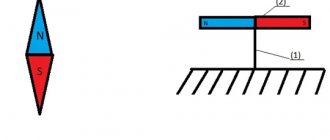
The area where the qualities of a magnet are demonstrated most forcefully are called the poles. A magnet has two poles: north (N) and south (S). Two identical fields (N - N) repel, and opposite ones (N - S) attract.
If a permanent magnet is divided in half, then these parts will also have two poles.
Circulation of the magnetic induction vector
To calculate the magnetic induction of simple magnetic fields, the Biot-Savart-Laplace law is sufficient. However, with more complex magnetic fields, for example, the magnetic field of a solenoid or toroid, the number of calculations and the cumbersomeness of the formulas will increase significantly. To simplify calculations, the concept of circulation of the magnetic induction vector is introduced.
Circulation of the magnetic induction vector along an arbitrary contour.
's imagine some circuit l , which is perpendicular to the current I. At any point P of a given circuit, the magnetic induction B is directed tangentially to the given circuit. Then the product of vectors dl and B is described by the following expression
Since the angle dφ is quite small, the vector dlB is defined as the length of the arc
Thus, knowing the magnetic induction of a straight conductor at a given point, we can derive an expression for the circulation of the magnetic induction vector
Now it remains to integrate the resulting expression over the entire length of the contour
In our case, the magnetic induction vector circulates around one current, but in the case of several currents, the expression for the circulation of magnetic induction turns into the law of total current, which states:
The circulation of the magnetic induction vector in a closed loop is proportional to the algebraic sum of the currents that the given loop covers.
