AC motors have gained the most popularity among all existing types of electric drives. What are their advantages? What are the main operating principles? We'll talk about everything in detail below.
AC motor
AC motors were needed around the middle of the 19th century, when the mass introduction of single-phase lighting networks began. The first AC drive is considered to be a synchronous motor based on permanent magnets, which was assembled by Charles Winston in 1841.
Nikola Tesla
Such engines had no starting torque, so only machines created by Thomson and Siemens in 1884-1885 began to be used in practice. At the same time, engines of much greater power were created. This is due to the mathematical formulation of the concept of a magnetic field that rotates (credit to Galileo Ferraris). Nikola Tesla was able to implement the concept in his synchronous and asynchronous polyphase drives. These units were put into mass production.
There are three main types of AC motors. What are these units and what are their differences? We'll talk about this below.
General information about MAT
The segment of MPT or electromechanical converters can be divided into single-phase and three-phase systems. Also at the basic level, asynchronous, synchronous and collector devices are distinguished, while the general principle of operation and design of them have many similarities. This classification of AC machines is conditional, since modern electromechanical conversion stations partially involve work processes from each group of devices.
As a rule, the MPT is based on a stator and a rotor, between which an air gap is provided. Again, regardless of the type of machine, the work cycle is based on the rotation of the magnetic field. But if in a synchronous installation the movement of the rotor corresponds to the direction of the force field, then in an asynchronous machine the rotor can move in a different direction and with different frequencies. This difference also determines the features of the use of machines. So, if synchronous ones can act both as a generator and as an electromechanical motor, then asynchronous ones are mainly used as motors.
As for the number of phases, single- and multi-phase systems are distinguished. Moreover, from the point of view of practical use, representatives of the second category deserve attention. These are for the most part three-phase AC machines, in which the magnetic field functions as an energy carrier. Single-phase devices, due to operational impracticality and large size, are gradually falling out of practice, although in some areas the decisive factor in their choice is low cost.
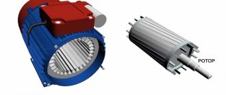
Asynchronous motor
The first asynchronous unit was invented by engineer Mikhail Osipovich Dolivo-Dobrovolsky. The engine was three-phase and had a squirrel-cage rotor type.
This was the beginning of a revolution in industry in all countries of the world.
The “asynchronous” in the name means that the magnetic field in the motor stator always rotates at a higher frequency than the rotor.
Device
The main elements are the stator and rotor.
The stator has a cylindrical shape; the part itself is assembled from steel sheets. The windings are placed in the stator slots. The latter is made from a special winding wire. The axis of each winding in the stator is shifted by 120° relative to all others. There are two types of connection of the ends of the windings: triangle and star. The choice of type depends on the network voltage.
In this type of engine there are two types of rotor: squirrel-cage and phase.
Squirrel cage rotor
Squirrel-cage rotors are also assembled from steel sheets. Molten aluminum is poured into the grooves, which forms some kind of rods. They are short-circuited by end rings. This design is also called a “squirrel cage”. It is the short-circuited winding of the armature (rotor).
Slip rotor
In a wound rotor there is a three-phase winding, almost the same as in the stator. Its ends are connected according to a star pattern, and those that remain free are brought to the rings. They are also connected to brushes that allow the insertion of a resistor. It helps to change the active resistance in the armature circuit. This reduces large inrush currents.
Principle of operation
The magnetic field of the stator interacts with the currents that this same field induces in the rotor. In this case, rotation will occur only when there is a certain difference in the frequency of rotation of the magnetic fields. This is the fundamental operating principle of an asynchronous electric motor.
Differences from DC machines
The fundamental design difference lies in the location of the winding. In AC systems it covers the stator, and in DC machines it covers the rotor. In both groups, electric motors differ in the type of current excitation - mixed, parallel and series. Today, AC and DC machines are used in industry, agriculture and in the domestic sphere, but the first option is more attractive in terms of its performance. AC generators and motors benefit from improved design, reliability and high energy efficiency.
The use of devices operating on direct current is common in areas where the requirements for precision control of operating parameters come to the fore. These can be traction mechanisms of transport, processing machines and complex measuring instruments. In terms of performance, DC and AC machines have high efficiency, but with different possibilities for technical and design adjustment to specific application conditions. Working with constant current gives you more control over speed, which is important when servicing servo motors and stepper motors.
Introduction
AC motors are electrical machines that convert electrical energy into mechanical energy. They are also the most advanced and common type of drive for machines and mechanisms that convert electrical energy into mechanical energy.
Electric motors are based on the process of electromagnetic induction, which occurs when a conductive medium moves in a magnetic field.
The conductive medium is usually a winding consisting of a sufficiently large number of conductors that are suitably connected to each other. The magnetic field in the motor is generated either by permanent magnets or by field windings that carry currents. Electric motors are reversible, i.e. in generator mode, they can convert electrical energy into mechanical energy and vice versa.
Electric motors consist of a protective housing containing a stationary hollow cylindrical stator consisting of individual insulated plates of electrical (magnetic) steel. The field windings, made of copper wire, are located in grooves on the inside of the stator. Inside the stator there is a movable rotor rotating on a shaft, which also consists of steel plates, which are also insulated from each other with heat-resistant varnish. Copper windings are located in the rotor slots. The stator winding is connected to an alternating current source.
Asynchronous motors are divided into synchronous and asynchronous depending on the ratio of speed and frequency.
Induction motors have a duty rating corresponding to continuous, short, intermittent or intermittent duty. Electric motors also have ratings.
In the manufacture and selection of electric motors, operating conditions and climatic conditions are of great importance, depending on the type of electric motors used, which have design features that make them suitable for operation in various conditions.
When choosing an electric motor, it is necessary to take into account its efficiency and electricity losses in the conductors feeding the motor.
AC motors are essential to meet the demands of industrial production. They are used in most electric drives. Synchronous electric motors are used, for example, as motors in large installations such as reciprocating compressors, air ducts, hydraulic pumps, etc.
Asynchronous motors are also used in industry, for example, to drive universal crane systems, as well as various cargo winches and other equipment needed in production.
All these questions require further thought and study.
Therefore, the purpose of the dissertation must be formulated.
The topic of the dissertation is asynchronous AC motors.
To achieve this goal, it is necessary to solve the following tasks:
- Analysis of basic information about asynchronous AC motors and their purpose;
- study of key indicators;
- a description of how it works;
- Price characteristic specification.
The purpose and objectives of the dissertation determined the choice of its structure. The article consists of an introduction, five chapters, a conclusion and a list of references used in writing the article.
Finally, the most important results of the thesis are summarized.
Asynchronous MPT device
For the technical basis of this device in the form of a rotor and stator, sheet steel is used, which is covered with an insulating oil-rosin layer on both sides before assembly. In low-power machines, the core can be made of electrical steel without additional coating, since the insulator in this case is the natural oxide layer on the metal surface. The stator is fixed in the housing, and the rotor is fixed on the shaft. In high-power asynchronous AC machines, the rotor core can also be attached to the housing rim with a sleeve mounted on the shaft. The shaft itself must rotate on bearing shields, which are also fixed to the base of the housing.
The outer surfaces of the rotor and the inner surfaces of the stator are initially provided with slots to accommodate the winding conductors. In the stator of AC machines, the winding is often three-phase and connected to the corresponding 380 V network. It is also called primary. The rotor winding is made similarly, the ends of which usually form a connection in a star configuration. Slip rings are also provided, through which a rheostat for adjustment or a three-phase starting element can additionally be connected.
It is also important to note the parameters of the air gap, which serves as a damper zone that reduces noise, vibration and heating during operation of the device. The larger the car, the larger the gap should be. Its size can vary from one to several millimeters. If it is structurally impossible to leave enough space for the air zone, then an additional cooling system for the installation is provided.
Device
The machine, operating on both direct and alternating current, consists of two parts:
- stationary - inductor or stator;
- rotating inside it - an armature or a rotor.
Each node consists of a core and a winding placed in its slots. The difference between Ipost and Iper machines. consists in the order of current supply: in the first case - to the winding of the rotating part, in the second - to the stationary part.
Another feature: the stator and rotor cores are made from separate insulated sheets of electrical steel, which prevents the occurrence of eddy currents in them.
The concepts “inductor” and “armature” refer to DC machines.
Operating principle of asynchronous MPT
In this case, the three-phase winding is connected to a symmetrical network with three-phase voltage, as a result of which a magnetic field is formed in the air gap. Regarding the armature winding, special measures are taken to achieve a harmonic spatial field distribution for the damper gap, which forms a system of rotating magnetic poles. According to the principle of operation of an alternating current machine, a magnetic flux is formed at each pole, which crosses the contours of the winding, thereby provoking the generation of electromotive force. A three-phase current is induced in the three-phase winding, providing torque to the motor. Against the background of the interaction of the rotor current with magnetic fluxes, an electromagnetic force is formed on the conductors.
If the rotor, under the influence of an external force, is set in motion, the direction of which corresponds to the direction of the magnetic field flows of the alternating current machine, then the rotor will begin to overtake the rate of rotation of the field. This occurs when the stator speed exceeds the rated synchronous frequency. At the same time, the direction of movement of electromagnetic forces will be changed. This creates a braking torque with reverse action. This operating principle allows the machine to be used as a generator operating in the mode of delivering active power to the network.
Principle of operation
Electric machines can act as:
- generator _ The installation produces a current due to the phenomenon of electromagnetic induction: changes in the magnetic flux crossing the conductor leads to the appearance of an EMF in it;
- engine _ Electromagnetic influence from the stator causes the moving component to rotate.
An important difference from Ipost devices: in motor mode, the magnetic field created by the stator rotates. This is due to the nature of Iper. (periodic change in magnitude and direction) and the location of the winding coils.
Based on the type of power supply, electric machines are divided into two types:
- single-phase . The stator coils are spaced at an angle of 1800, as a result of which when Iper flows into them. a pulsating magnetic field is formed. It can be thought of as the sum of two fields rotating in the opposite direction. The presence of a pulsating field is not enough to rotate the rotor, but if such movement is given to it from the outside, it will continue to rotate in the same direction. This is due to the fact that, due to electromagnetic interaction, the moving element extinguishes that component of the pulsating magnetic field that is directed against its rotation. As a result, only one rotating magnetic field remains active, and it drags the rotor along with it. In the early stages, the rotor was spun manually; today, a starting winding, shunting, or starting through a capacitor is used for this;
- three-phase . The windings of phases A, B and C are spaced by a third of the period (in a single-pole machine this is 120 degrees), as a result of which, due to the difference in currents in the phases, the resulting magnetic field seems to rotate in one direction. Obviously, during the period it will make one revolution, that is, at a current frequency of 50 Hz, the field rotates at a speed of 3000 rpm. If you install an electromagnet with two pairs of poles on the rotor, and 6 equidistant coils on the stator, connected to the phases in the sequence A - B - C - A - B - C, then the field rotation speed will be halved: to 1500 rpm. It is equal to W = (60*f)/n, where f is the frequency of the electric current, n is the number of pairs of poles and coils connected to one phase.
The above applies to both the engine and the generator. That is, to create a 3-phase current with a frequency of 50 Hz in the presence of 30 pairs of poles, the rotor needs to be rotated at a speed of only 100 rpm instead of 3000, which is important for hydroelectric power station rotors.
No matter how many coils there are, they are all combined into 3 single-phase groups, so the stator of a 3-phase electric machine always has 6 output terminals. In groups, the coils are connected in parallel or in series.
Design and principle of operation of synchronous MPTs
In terms of design and stator location, a synchronous machine is similar to an asynchronous one. The winding is called an armature and is made with the same number of poles as in the previous case. The rotor has an excitation winding, the energy supply of which is provided by slip rings and brushes connected to a direct current source. By source we mean a low-power generator-exciter installed on one shaft. In an AC synchronous machine, the winding acts as a primary magnetic field generator. During the design process, designers strive to create conditions so that the inductive distribution of the excitation field on the stator surfaces is as close to sinusoidal as possible.
At increased loads, the stator winding forms a magnetic field with rotation in the direction of the rotor with a similar frequency. In this way, a single rotation field is formed, in which the stator field will influence the rotor. This design of AC machines allows them to be used as electric motors, if a three-phase current supply to the synchronous winding is initially provided. Such systems create conditions for coordinated rotation of the rotor at a frequency corresponding to the stator field.
AC Electrical Machines
AC electrical machines. Purpose, scope of application, device, principle of operation of machines.
AC machines are of two types. These are synchronous and asynchronous machines. In synchronous machines, the rotor speed strictly depends on the frequency of the alternating current. We can say the rotation speed is “synchronous” with the frequency of the current. It is not difficult to guess that in asynchronous machines the rotation speed generally depends on the load on the shaft, and not on the frequency of the supply current. In addition to dividing into synchronous and asynchronous electric machines, they are also divided according to their purpose. These could be generators. That is, a machine that converts mechanical rotational energy into alternating electric current. A machine that converts electrical energy into mechanical energy is called a motor. There is also another class of electric machines. They convert electrical energy, also into electrical energy, but of a different frequency or voltage. A synchronous AC machine is a machine in which: the main magnetic field, that is, the stator field, is created by direct current. In a particular case, it could even be a permanent magnet. And the rotor rotates at the frequency of the current change.
Formula 1 - dependence of the rotor speed of a synchronous machine on the frequency of alternating current. where n is the frequency at which the rotor rotates, measured in revolutions per minute. That is, how many full revolutions the rotor will make in one minute. f frequency of the supply alternating current p number of pairs of poles in the magnetic system of the machine
Currently, asynchronous machines are used mainly in motor mode. Machines with a power of more than 0.5 kW are usually made three-phase, and with less power - single-phase.
For the first time, the design of a three-phase asynchronous motor was developed, created and tested by our Russian engineer M. O. Dolivo-Dobrovolsky in 1889-91. The demonstration of the first engines took place at the International Electrotechnical Exhibition in Frankfurt am Main in September 1891. Three three-phase motors of different power were presented at the exhibition. The most powerful of them had a power of 1.5 kW and was used to drive a DC generator. The design of an asynchronous motor proposed by Dolivo-Dobrovolsky turned out to be very successful and is the main type of design of these motors to this day.
Over the past years, asynchronous motors have found very wide application in various industries and agriculture. They are used in electric drives of metal-cutting machines, hoisting and transport machines, conveyors, pumps, and fans. Low-power motors are used in automation devices.
The widespread use of asynchronous motors is explained by their advantages compared to other motors: high reliability, the ability to operate directly from an alternating current network, and ease of maintenance. The stationary part of the machine is called the stator
, movable –
rotor
.
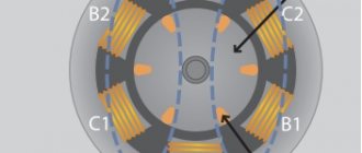
The stator core is assembled from sheet electrical steel and pressed into the frame. In Fig. Figure 2.1 shows the stator core assembly. The bed (1) is made of cast, non-magnetic material. Most often the frame is made of cast iron or aluminum. On the inner surface of the sheets (2), from which the stator core is made, there are grooves into which the three-phase winding
(3) is placed. The stator winding is made mainly of insulated copper wire of round or rectangular cross-section, less often of aluminum.
The stator winding consists of three separate parts called phases. The beginnings of the phases are indicated by the letters c
1,
c
2,
c
3, ends –
c
4,
c
5,
c
6.
The beginnings and ends of the phases are brought out to a terminal block fixed to the frame. The stator winding can be connected in a star or delta configuration. The choice of connection diagram for the stator winding depends on the line voltage of the network and the motor rating data. The passport of a three-phase motor specifies the line voltages of the network and the connection diagram of the stator winding. For example, 660/380, Y/∆. This motor can be connected to a network with U
l=660V according to a star circuit or to a network with
U
l=380V - according to a triangle circuit.
The main purpose of the stator winding is to create a rotating magnetic field in the machine.
Rotor core
It is assembled from sheets of electrical steel, on the outer side of which there are grooves into which the rotor winding is placed.
There are two types of rotor winding: short-circuited
and
phase
. Accordingly, asynchronous motors come with a squirrel cage rotor and a wound rotor (with slip rings).
The short-circuited rotor winding consists of rods 3, which are placed in the grooves of the rotor core. At the ends, these rods are closed with end rings 4. This winding resembles a “squirrel wheel” and is called the “squirrel cage” type. A squirrel-cage motor has no moving contacts. Due to this, such engines are highly reliable. The rotor winding is made of copper, aluminum, brass and other materials.
Dolivo-Dobrovolsky was the first to create an engine with a squirrel-cage rotor and study its properties. He found out that such engines have a very serious drawback - limited starting torque. Dolivo-Dobrovolsky named the reason for this shortcoming - a heavily shorted rotor. He also proposed the design of an engine with a wound rotor.
Single-phase asynchronous motors.
An asynchronous motor is the simplest of electrical machines. Like any electrical machine, it has two main parts: the stator and the rotor.
The stator (Fig. 6.1) consists of a cast iron frame 1, in which a magnetic circuit 2 is fixed in the form of a hollow cylinder. A gap is usually left between the frame and the core through which cooling air passes. To reduce losses due to eddy currents, the magnetic circuit is assembled from thin (0.5 mm) sheets of electrical steel, insulated from each other with varnish.
Rice. 6.1. Stator design of asynchronous motor:
1 - bed; 2 - core; 3 - winding;
4 - paw; 5 - gasket
Winding 3 is placed in the grooves cut along the inner circumference of the stator. For a two-pole machine, the stator winding consists of three coils shifted at angles of 120°, for a four-pole machine it consists of six coils shifted by 60°, for a six-pole machine it consists of nine coils, etc. d. The winding in the stator slots is secured with wedges.
The rotor is also made of thin sheets of electrical steel. A winding is placed in the rotor slots, which can be short-circuited or phase-type (Fig. 6.2). Short circuit winding type
Rice. 6.2. General view of the rotor of an asynchronous motor with short-circuited (a) and phase (b) windings
The “squirrel cage” is shown in Fig. 6.3. It consists of thick conductive rods (copper, aluminum) connected at the ends with copper or aluminum rings. The short-circuited winding is not isolated from the rotor. Sometimes it is made by pouring molten aluminum into the slots of the rotor.
Slip rings1, made of brass or copper, are secured to the motor shaft using insulating spacers. A brush holder with carbon or copper-graphite brushes 2 is mounted on the bearing shield.
Rice. 6.3. General view of a short-circuited squirrel cage winding
Rice. 6.4. Connection diagram of the rotor phase winding with adjusting rheostats:
1—contact rings, 2—brushes; 3 - rheostats
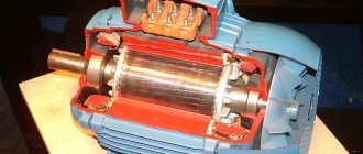
A general view of an asynchronous motor is shown in Fig. 6.5.
Rice. 6.5. General view of an asynchronous motor with squirrel-cage (a) and phase-phase (b) rotor windings
Operating principle of an asynchronous motor.
The operating principle of an asynchronous motor is based on the use of a rotating magnetic field and the basic laws of electrical engineering.
When the motor is turned on in a three-phase current network, a rotating magnetic field is formed in the stator, the power lines of which intersect the rods or coils of the rotor winding. In this case, according to the law of electromagnetic induction, an EMF is induced in the rotor winding, proportional to the frequency of intersection of the power lines. Under the influence of the induced EMF, significant currents arise in the squirrel-cage rotor.
In accordance with Ampere's law, current-carrying conductors located in a magnetic field are subject to mechanical forces, which, according to Lenz's principle, tend to eliminate the cause of the induced current, i.e., the intersection of the rotor winding rods with the force lines of the rotating field. Thus, the resulting mechanical forces will spin the rotor in the direction of field rotation, reducing the speed of intersection of the rotor winding rods with magnetic lines of force.
The rotor cannot reach the frequency of field rotation in real conditions, since then the rods of its winding would be stationary relative to the magnetic lines of force and the induced currents in the rotor winding would disappear. Therefore, the rotor rotates at a frequency lower than the field rotation frequency, that is, asynchronously with the field, or asynchronously.
If the forces braking the rotation of the rotor are small, then the rotor reaches a frequency close to the frequency of rotation of the field. As the mechanical load on the motor shaft increases, the rotor speed decreases, the currents in the rotor winding increase, which leads to an increase in motor torque. At a certain rotor speed, a balance is established between braking and torque.
Synchronous motor
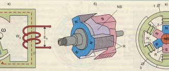
The stator structure of a synchronous motor is similar to the stator structure of an asynchronous motor. The rotor of a synchronous motor is an electromagnet or permanent magnet (Fig. 6.6).
The operating principle of a synchronous motor is illustrated in Fig. 6.7. Inside the magnet N1 S1 there is a magnet NS. If magnet N1 S1 is rotated, it will pull magnet NS along with it. In stationary mode, the rotation speeds of both magnets are the same.
A mechanical load can be applied to the NS magnet shaft. The greater this load, the greater the angle of lag of the NS magnet axis from the NiSi magnet axis. At some load, the attractive forces between the magnets will be overcome and the rotor will stop.
In a real motor, the field of magnet N1 S1 is replaced by a rotating magnetic field of the stator; in this case, the rotor either rotates synchronously with the magnetic field of the stator, lagging behind by an angle, or stops (falls out of synchronism) when overloaded. Thus, regardless of the load, the rotor always rotates at a constant frequency equal to the rotation frequency of the stator magnetic field:
Rice. 6.6. Schematic representation Fig. 6.7. To explain the principle of a synchronous motor, the operation of a synchronous motor
Constancy of rotation speed is an important advantage of a synchronous motor. Strict constant rotation speed is required in many areas of technology, for example, when recording and reproducing sound. The disadvantage of a synchronous motor is the difficulty of starting: to start, you need to spin the rotor in the direction of rotation of the stator field. For this purpose, a special short-circuited winding embedded in the rotor is most often used. At the moment of starting, the engine operates as asynchronous. When the rotor speed approaches the stator field speed, the rotor enters synchronism and the motor operates as a synchronous motor. In this case, the short-circuited winding turns out to be de-energized, since the rotor rotation frequency is equal to the stator field rotation frequency and the rotor winding rods are not intersected by magnetic lines of force.
Currently, there is a tendency to replace DC electrical circuits on moving objects (ships, airplanes, cars) with high-frequency AC circuits (200, 400 Hz and higher). The ability to use brushless AC machines, transformers and magnetic amplifiers makes it possible to increase the reliability of the circuit, as well as reduce the size and weight of machines and devices.
When equipping a facility with an alternating current network, alternating current electric drives are widely used. Circuits with asynchronous and synchronous motors have been developed that allow performing all operations previously performed by DC motors.
The advantages of asynchronous motors are especially noticeable when, due to the operating conditions of the drive, there is no need for smooth control of the rotation speed over a wide range and large starting torques (drive of pumps, fans, etc.).
Synchronous motors are especially useful for driving gyroscope rotors. In cases where a gyroscope is used for particularly precise measurements (for example, in ballistic missiles), the gyroscope rotor is driven by a synchronous motor. In this case, the rotor speed depends only on the design of the motor and the frequency of the supply current, which can be stabilized with a very high degree of accuracy.
Synchronous generator
The rotor of synchronous machines rotates synchronously with a rotating magnetic field (hence their name). Since the rotation speeds of the rotor and the magnetic field are the same, no currents are induced in the rotor winding. Therefore, the rotor winding receives power from a DC source.
The stator structure of a synchronous machine (Fig. 6.8) is practically no different from the stator structure of an asynchronous machine.
Figure 6.8. General view of the stator of a synchronous generator.
Figure 6.9. General view of a non-salient pole rotor of a synchronous generator.
The rotors of synchronous generators can be salient-pole (Fig. 6.9) and non-salient-pole (Fig. 6.10). In the first case, synchronous generators are driven by low-speed turbines of hydroelectric power plants, in the second - by steam or gas turbines of thermal power plants.
Rice. 6.10. General view of a non-salient-pole rotor of a synchronous generator
Various methods of exciting synchronous generators are used. A synchronous generator with a machine exciter, which is a direct current generator located on the same shaft as the synchronous generator, has become widespread. The machine exciter is driven by the same prime mover as the synchronous generator. The exciter output terminals are connected through brushes and rings to the rotor winding of the synchronous generator. The voltage of the synchronous generator can be regulated by a rheostat in the exciter field winding circuit, which is convenient and energetically beneficial, since relatively small currents flow in this winding.
Generators with self-excitation through semiconductor or mechanical rectifiers are also used.
Of the characteristics of a synchronous generator, the external characteristics that express the dependence of the voltage at the generator terminals on the load current at constant values of the excitation current, frequency and power factor are of greatest practical interest.
Salient-pole and non-salient-pole synchronous machines
The main difference between salient pole systems is the presence of protruding poles in the design, which are attached to special shaft protrusions. In typical mechanisms, fixation is performed using T-shaped tail fasteners to the crosspiece rim or shaft through a sleeve. In the design of low-power AC machines, the same problem can be solved by bolted connections. The winding material is strip copper, which is wound onto an edge, insulated with special gaskets. The terminals with poles in the grooves house the winding rods for starting. In this case, a high resistivity material like brass is used. The winding contours at the ends are welded to the short-circuiting elements, forming common rings for a short circuit. Salient-pole machines with a power potential of 10-12 kW can be made in the so-called reversed design, when the armature rotates and the poles of the inductor remain stationary.
For non-salient pole machines, the design is based on a cylindrical rotor made of steel forging. The rotor contains grooves for forming an excitation winding, the poles of which are designed for high rotation speeds. However, the use of such a winding in electrical machines with high-power alternating current is impossible due to the high degree of rotor wear under harsh operating conditions. For this reason, even in medium-power installations, high-strength components made from solid forgings based on chromium-nickel-molybdenum or chromium-nickel steels are used for rotors. In accordance with the technical requirements for strength, the maximum diameter of the working part of the rotor of a non-salient-pole synchronous machine cannot be higher than 125 cm. This explains the unusual form factor of the rotor with an elongated body, although there are restrictions on this parameter associated with increased vibrations for too long elements. The maximum rotor length is 8.5 m. Non-salient-pole units used in industry include various turbogenerators. With their help, in particular, they connect the operating torques of steam turbines with thermal power plants.
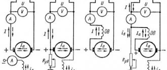
Key indicators
When selecting an AC motor, features such as
Their efficiency, defined as the ratio of the useful power they use to the total power supplied to a given appliance.
The power factor of a transmission line, called power factor or "cosine phi" value. This coefficient is equal to the ratio of the active power of the electrical circuit to the total power supplied to it. The magnitude of the cosine charge depends on the design and operating principle of electrical equipment, electrical networks and systems. The higher the cosine value, the closer it is to 1, the more efficient and economical electricity is consumed. This value should not be lower than 0.9.
When evaluating electric motors, their performance characteristics are also used, i.e. dependence of engine parameters on shaft power. That's right: Speed, torque, power factor characteristics, efficiency.
There are also the following features that characterize this type of product.
The rated operating mode is the operating mode for which the engine is designed.
The nominal parameters of the electric machine, which characterize the nominal operating mode of the machine, refer to the operation of the machine at an altitude of up to 1000 m above sea level and at a temperature of the gaseous cooling medium up to +40 degrees Celsius and cooling water up to +30 degrees.
Rated operating modes of electrical machines, including long, short, repeated and intermittent modes.
Rated power - effective mechanical power on the shaft, expressed in W, kW, MW, indicated on the motor nameplate.
Rated voltage - corresponds to the rated operating mode of the electric motor.
Rated motor excitation voltage.
The rated current of an electric motor is the current corresponding to the rated operating mode.
The rated excitation current of the motor is the excitation current corresponding to the rated operating mode.
Rated speed of an electric machine.
Changing the rated speed of the electric motor.
The parameters necessary to characterize electric motors also include: operating temperature of individual engine parts, inertia coefficient, initial starting current, initial starting torque, minimum torque, maximum torque, maximum permissible temperature rise of engine parts, height of the electric motor rotation axis.
Technical and economic indicators - size, weight and cost of the electric motor - depend on its main dimensions - the internal diameter of the reinforcement core and its length. The main dimensions, in turn, depend on the engine power, rotation speed and the main electromagnetic loads in the nominal operating mode - ejection in the air gap and linear load.
The entire set of parameters allows us to characterize this type of product.
Features of vertical hydro generators
A separate class of salient-pole synchronous MPTs provided with a vertical shaft. Such installations are connected to hydraulic turbines and selected according to the power of the flows being served according to the rotation frequency. Most AC machines of this type are low-speed, but have a large number of poles. Among the critical working components of a vertical hydraulic generator, we can note the thrust bearing and thrust bearing, which bear the load from the rotating parts of the engine. In particular, the pressure from the flow of water that acts on the turbine blades is also applied to the thrust bearing. In addition, a brake is provided to stop rotation, and the working structure also contains guide bearings that absorb radial forces.
At the top of the machine, along with the hydraulic generator, auxiliary units can be placed - for example, a generator exciter and a regulator. By the way, the latter is an independent alternating current machine with windings and poles of permanent magnets. This installation provides power to the motor to provide the automatic governor function. In large vertical hydrogen generators, the exciter can be replaced by a synchronous generator, which, together with exciter units and mercury rectifiers, provides energy supply to power devices that serve the working process of the main hydro generator. The machine's vertical shaft configuration is also used as a drive mechanism for high-power hydraulic pumps.
Bibliography
- Atabekov V.B. Repair of transformers, electrical machines and equipment. - M.: Secondary school, 1988.
- Bruskin D.E. and others. Electrical machines. - M.: Higher School, 1983
- Instructions for quality acceptance of industrial and technical products and consumer goods No. P-7 dated April 25, 1965
- Nikolaeva M.A. Certification of consumer goods. - M.: Economics, 1997
- All-Russian classifier of types of economic activities, products and services. Volume 1.2 - Moscow: Priority Publishing House, 1999.
- Main types of industrial equipment, electrical equipment and devices / Ed. - M.: Higher School, 1986.
- Savichev O.P., Kozachev L.A. Industrial equipment: Textbook. - L.: Publishing house LFEI, 1986.
- Knowledge of industrial equipment products: a textbook. Part 2: Tutorial.
- Electrical equipment and instruments. - St. Petersburg: St. Petersburg State University of Economics and Economics Publishing House, 1993.
- Expertise in the field of retail trade / ed. prof. Yu.N. Golubeva: Textbook. - St. Petersburg: St. Petersburg State University of Economics and Finance, 1997 - 235 p.
- Manual on electrical engineering: in 3 volumes. T.2. electrical devices / edited by MPEI V.G. Gerasimov, P.G. Grudinsky, L.A. Zhukov and others - 6th ed. S. and add. - M.: Energoizdat, 197 8.
Collector MPT
The presence of a collector unit in the MPT design is often determined by the need to perform the function of converting the rotational speed in the electrical connection of different-frequency circuits on the rotor and stator windings. This solution allows you to provide the device with additional operational properties, including automatic regulation of operating parameters. AC commutator machines that are connected to three-phase networks receive three brush fingers in each double-pole segment. The brushes are connected to each other in a parallel circuit using jumpers. In this sense, commutator MMTs are similar to direct current electric motors, but differ from them in the number of brushes used on the poles. In addition, the stator in this system may have several additional windings.
The closed armature winding when using a commutator with three-phase brushes will be a three-phase complex winding with a delta connection. During the rotation of the armature, each phase of the winding maintains a constant position, but the sections alternately move from one phase to another. If an AC commutator machine uses a six-phase set of brushes shifted by 60° relative to each other, then a six-phase winding is formed with a polygon connection. On the brushes of a multiphase machine with a commutator group, the current frequency is determined by the rotation of the magnetic flux with respect to the stationary brushes. The direction of rotation of the rotor can be either counter or coordinated.
How to change the direction of rotation of the rotor in an AC drive?
Of all AC machines, asynchronous ones, powered by a voltage of 380V, have become the most popular. We'll talk about their reverse.
The first thing you need to know is that to reverse an asynchronous motor, changing two phases is enough.
The most common connection scheme is with two magnetic starters. For reversing DC motors, it is not particularly different; in our case, the use of two-pole starters is typical, as even its name suggests: “reversing starter circuit.”
AC motor reverse
When the KM1 starter is turned on using the “Start 1” button, voltage begins to be supplied to the windings, while the “Start 2” button will be blocked from unscheduled activation. This occurs due to the fact that the normally closed contacts of KM1 open. The rotor begins to rotate.
When the KM1 starter is turned off using the “Stop” button (you can also remove the voltage), pressing the “Start 2” button turns on KM2. The result is a direct feed through the contacts of line L2, lines L1 and L3 take each other's places. Now the “Start 1” button is blocked, because the normally closed contacts of KM2 open. Rotation begins in the opposite direction.
This scheme is applicable to all asynchronous three-phase motors. Ease of implementation and accessible parts are the main positive aspects.
Reverse is often carried out thanks to electric power. engine control systems. Their switching circuits are assembled using thyristors; there are no starters. However, they can be installed to allow remote switching on/off in a circuit.
Connecting a pulse-phase control system
Devices based on thyristors are much more reliable, although they are more complex than those based on contactors. They use pulse-phase and frequency control systems. Such devices perform several functions: changing the direction of rotation of the rotor in the engine, as well as regulating its rotation speed.
In everyday life, sometimes you need to connect a 380V motor to a 220V network with the ability to reverse. To do this, first of all you need to reconnect the winding according to a different circuit (star or triangle).
Winding connection diagrams
If there is a need to connect an asynchronous three-phase electric drive to a single-phase network, then you need to use capacitor motors. The capacitor can be connected separately according to the diagram below.
In order for the reverse to be carried out, the contact from the network under the letter B must be connected to the terminal under the letter A. For the capacitor, the opposite is true: disconnect from A and connect to terminal B. For maximum convenience, it is better to use a six-pin toggle switch.
The main feature of modern AC motor control circuitry is versatility. Often it includes not only a mechanism through which reverse is carried out, but also one that helps control the rotor speed. This scheme began to spread due to the development of microprocessors. Microprocessor electronics are the basis for the operation of modern frequency converters. Such blocks for controlling variable machines are characterized by their high reliability and “pleasant” price. Another significant advantage of the multifunctional control system is significant energy savings (about 40%). AC motors can be controlled based on one of two principles. The methods are listed below:
- principle of voltage-frequency regulation;
- vector control principle.
With the volt-frequency (or scalar) principle of electric motor control, the shaft rotation speed changes by changing the frequency and voltage in the stator. The voltage module also changes. There are ultimately two regulating factors: frequency and voltage. They have the same meaning. For the engine to work, it is important that the ratio of the voltage in the stator winding and its voltage be constant. In other words, any change in frequency must be synchronized with a change in voltage and vice versa. The drive efficiency does not change during this time.
The convenience of this scheme is that simultaneous operation with several devices is possible. This is critically important during the operation of complex technological lines, for example, when monitoring how a conveyor moves. With voltage-frequency regulation, the maximum possible range is 1/40. This is enough to solve almost all production problems.
Among the negative qualities of the circuit, we can mention the inability to control the torque and positioning mode. The main area of application of this control method is conveyors, pumps, fans.
With vector control of an electric motor, it is possible to carry out not only the regulation described above, but also work with the magnetic flux. The basis of the system is the representation of the main engine parameters as vectors in space. Vector control chips are designed to control and change both the amplitude and phase of the electric current in the stator. This actually changes its vector. The result is the ability to control the torque of the electric motor.
In order for current phase control to be effective, it is necessary to understand what state it is in at a particular moment. This problem is solved by a sensor that monitors the position of the rotor or a system that determines its position based on two parameters: voltage and currents in the windings of the static part of the engine. If there is a device that controls feedback, it can be adjusted in the range of 1-1000 with an accuracy of hundredths of a percent.
Application of MPT
Today, MPTs are used wherever the generation of mechanical or electrical energy is required in one form or another. Large productive units are used in the maintenance of engineering systems, power stations and lifting and transport units, and low-power units are used in ordinary household appliances from fans to pumps. But in both cases, the purpose of alternating current machines is to generate sufficient energy potential. Another thing is that the design differences, the implementation of the internal configuration of the stator and rotor, as well as the control infrastructure are of fundamental importance.
Although the general design of the MPT for a long time retains the same set of functional components, increasing requirements for the operation of such systems force developers to introduce additional monitoring and control elements. At the present stage of technological development, especially in the context of the use of alternating current machines in the industrial sector, it is difficult to imagine the operation of such engines and generators without high-precision means of regulating operating parameters. For this, a variety of control methods are used - pulse, frequency, rheostat, etc. The introduction of automation into the regulatory infrastructure is also a characteristic feature of modern MPT operation. The control electronics are connected to the power plant on one side, and on the other to software controllers, which, according to a given algorithm, give commands to set specific parameters for the operation of the mechanism.
Price specification
Until 1996, prices for electric motors grew at a tremendous pace, so that in 1995 the price dynamics was 280%, and since 1996 the price increase has slowed down significantly and amounted to 130%. Price growth until 1996 was mainly due to inflation in Russia, and after the economic situation more or less stabilized, price growth slowed down. Later, price growth slowed. In January-March 1997, the rate of growth in prices for mechanical engineering products slowed down significantly. Over the three months of this year, factories producing mechanical engineering products increased prices by an average of 3 percent. During the corresponding period last year, the engineering industry increased prices for its products by 11.3%. In general, price dynamics in 1997 amounted to 107.4%. In 1998, the downward trend in prices continued. Thus, in the first quarter the price dynamics was 101.3%, in the second - 99.2%, but in the third quarter prices began to rise again, mainly due to the economic crisis, the depreciation of the ruble and rising inflation. In October 1998, the price dynamics was 105.9%. Prices continued to rise, which was also caused by the August crisis.
In principle, electric motors are made to order and the final price is determined at the conclusion of the contract. Moreover, the price depends on different versions of the motor (tropical, marine, etc.), so the price increases. The export version also increases the price of the engine.