Types and meaning of lines
- Thin and thick solid lines - in the drawings depict electrical lines, group communication lines, lines on UGO elements.
- Dashed line - indicates shielding of wire or devices; denotes a mechanical connection (motor - gearbox).
- Thin dash-dotted line - intended to highlight groups of several components that make up parts of a device or control system.
- A dot-dash line with two dots is a dividing line. Shows a breakdown of important elements. Indicates an object remote from the device that is connected to the system by mechanical or electrical communication.
Network connecting lines are shown in full, but according to the standards, they are allowed to be cut off if they interfere with the normal understanding of the circuit. The break is indicated by arrows; the main parameters and characteristics of the electrical circuits are indicated nearby.
A thick dot on the lines indicates a connection, soldering of wires.
Ground color
The color of the grounding wire, “ground”, is almost always indicated by yellow-green color
. Windings that are either completely yellow or light green are less common. The wire may be marked “PE”. You can also find green-yellow wires marked “PEN” and with blue braiding at the ends of the wire at the fastening points - this is grounding combined with neutral.
In the distribution panel (DP) it should be connected to the grounding bus, to the housing and the metal door of the panel. As for the distribution box, the connection goes to the grounding wires from the lamps and from the grounding contacts of the sockets. The ground wire does not need to be connected to the RCD (residual current device), therefore RCDs are installed in houses and apartments, since electrical wiring is usually carried out with only two wires
Grounding designation on the diagrams:
Conventional ground(1) Clean ground(2) Safety ground(3) Chassis ground(4) DC ground(5)
What is the difference between grounding
Connection using an electrical junction box
Work begins after the power supply cable is de-energized. Only this will guarantee that the master will not suffer from electric shock if he touches a bare wire or uninsulated contact
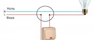
It is important to determine the “phase”
An indicator or tester will indicate which core has voltage. It should be disconnected at the entrance to the premises (house, apartment, office, workshop). Judging by the diagram, the switch is located between the input and the lamp. Moreover, the connection is made in such a way that in the “Off” position the current supply wire is broken, while the “neutral wire” remains intact. The diode on the indicator will light up if you touch it with a metal tip.
The functional significance of the distribution box is to distribute the current between the socket group, lighting, and other adjacent rooms. One of the branches is the input of power electrical cables stretched from the switchboard, an electric meter with “plugs” or “automatic machines”. In most cases, the developer is responsible for this, and residents, when carrying out repairs, have the right only to change the wiring, lay new branches, and change the wiring diagram for lamps and sockets.
Wire color coding
Anyone who has ever dealt with wires and electricity has noticed that conductors always have different insulation colors. This was done for a reason
The colors of the wires in electrics are designed to make it easier to recognize the phase, neutral wire and ground. They all have a certain color and are easily distinguished during operation. The color of the phase, neutral, and ground wires will be discussed further.
How phase wires are painted
When working with wiring, phase wires pose the greatest danger. Touching the phase, under certain circumstances, can become lethal, which is probably why bright colors were chosen for them. In general, the colors of electrical wires allow you to quickly determine which of a bunch of wires are the most dangerous and work with them very carefully.
Coloring of phase wires
Most often, phase conductors are red or black, but other colors are also found: brown, lilac, orange, pink, purple, white, gray. Phases can be painted in all these colors. It will be easier to deal with them if you exclude the neutral wire and ground.
In the diagrams, phase wires are designated by the Latin (English) letter L. If there are several phases, a numerical designation is added to the letter: L1, L2, L3 for a three-phase 380 V network. In another version, the first phase is designated by the letter A, the second by B, and the third by C .
Ground wire color
By modern standards, the ground conductor is yellow-green. It usually looks like yellow insulation with one or two longitudinal bright green stripes. But there are also transverse yellow-green stripes in color.
Grounding may be this color
In some cases, the cable may only have yellow or bright green conductors. In this case, the “earth” has exactly this color. It is displayed in the same colors on diagrams - most often bright green, but it can also be yellow. Signed on circuit diagrams or on ground equipment in Latin (English) letters PE. The contacts to which the “ground” wire must be connected are also marked.
What color is the neutral wire?
Zero or neutral is blue or light blue, sometimes blue with a white stripe. Other colors are not used in electrical engineering to indicate zero. It will be like this in any cable: three-core, five-core or with a large number of conductors.
What color is the neutral wire? Blue or cyan
“Zero” is usually drawn in blue on diagrams and signed with the Latin letter N. Experts call it a working zero, since, unlike grounding, it participates in the formation of the power supply circuit. When reading a diagram, it is often defined as "minus", while the phase is considered "plus".
How to check the correctness of marking and wiring
Take a multimeter and/or an indicator screwdriver. It’s easy to work with a screwdriver: when you touch a phase, the LED built into the housing lights up. So it will be easy to identify phase conductors. If the cable is two-wire, there are no problems - the second conductor is zero. But if the wire is three-wire, you will need a multimeter or tester - with their help we will determine which of the remaining two is phase and which is zero.
Determining the phase wire using an indicator screwdriver
We set the switch on the device so that the selected jackal is more than 220 V. Then we take two probes, hold them by the plastic handles, carefully touch the metal rod of one probe to the found phase wire, the second to the supposed zero. The screen should display 220 V or the current voltage. In fact, it may be significantly lower - this is our reality.
If 220 V or a little more is displayed, this is zero, and the other wire is presumably “ground”. If the value is less, we continue checking. With one probe we again touch the phase, with the second - to the intended grounding. If the instrument readings are lower than during the first measurement, there is “ground” in front of you and it should be green. If the readings turn out to be higher, it means that somewhere there was a mistake with “zero” in front of you. In such a situation, there are two options: look for exactly where the wires were connected incorrectly (preferable) or simply move on, remembering or noting the existing position.
And, in conclusion, let me give you some advice: when laying wiring and connecting wires, always connect conductors of the same color, do not confuse them. This can lead to disastrous results - at best, equipment failure, but there may also be injuries and fires.
This is interesting: How to unscrew the valve axle box from the mixer if it is stuck?
Preparatory work
The first thing you should do is turn off the power. Some people believe that it is enough to turn off only the circuit on which the breaker is to be installed, but we strongly recommend that you completely turn off the power to your apartment.
Use a voltage indicator on each wire to make sure it is safe to touch them. It's better to check several times before starting work.
The next step of the project is to clean the electrical outlet (installation box) from paint, small pieces of drywall, dust and dirt. This operation is very important, especially if we are talking about a newly renovated room or apartment in a new building. But even if you're replacing an old breaker, it's best to assess the condition of the socket box beforehand to make sure the new breaker can be installed and aligned properly.
Preparing the socket box for installing the switch.
Once you have purchased a new switch, you must disassemble it using a screwdriver or simply by hand, depending on its type and manufacturer. This operation is not necessary, since you will be connecting electrical wires to the inside of the switch. It is necessary to remove the switch buttons and frame.
Now you have to connect the wiring. Using pliers, cut off the excess length of the wires - they should protrude from the wall by about 15 cm. This length should be enough to connect the switch without much difficulty. The wires should not be left too long, otherwise they will be difficult to place inside the socket box.
Once you have cut the wires to the desired length, you can proceed to the next step. Using pliers, strip about 2 cm of insulation from each wire. Stripping a long length is dangerous, since exposed wires may accidentally come into contact during operation, causing a short circuit.
Use pliers to shape the end of each wire into an L-shape (or C-shape for some switches with side screws).
Tip: the easiest and most effective way to strip a wire is to use special insulation stripping pliers.
Removing insulation from wires.
What does L stand for?
Common symbols on light switches are applied to mark their contact connectors or to indicate the position in which their key is located.
Single-key switch connection diagram
Presumably, this symbol is taken from the first letter of the English word "Line", meaning line or linear wire. The second contact also has its own designation, which varies from manufacturer to manufacturer:
- The symbol L with a unit added to it is L1.
- The same sign, but with the addition of a stroke - L`.
- A small arrow pointing up.
- Just one (“1”).
A number of manufacturers do not indicate this outlet at all. If it is on top, a wire is led from it to the chandelier or junction box.
Connection diagram for two-button switch
The PUE stipulates from which sides conductors should be supplied and discharged to the switch. According to the requirements of the regulations, the connection is made from below, and the outlet is mounted from above.
For two-key and three-key devices, the number of output conductors increases to two and three, respectively, which forces their manufacturers to mark additional contacts. Therefore, their designations often contain icons such as L2, L3, or the same letter, but with two or three strokes. It is also possible that instead of letters next to the output terminals there are only numbers corresponding to the number of the output conductor.
Operating principle of a single-key switching element
Let's give a specific example to clarify the operating principle. The switching device is installed with a break in the conductor having a voltage of 220 V and connected to the lamp. There are 2 wires for such a switch in a single-phase electrical network.
Operating principle of a single-key switch Source samelectrik.ru
The first of them, codenamed “A,” connects the power panel to the switch and transports electric current through it. This wiring is always under electrical voltage of 220 Volts. Other wiring runs from the switching element to the light source and delivers current to it. When you press the switch, both contacts are connected to each other. Voltage is supplied to the lighting fixture and the lamps immediately light up. Returning the switch to its original position breaks the circuit connection, the contact disappears, so the lamp goes out due to the lack of current in it.
The coding “L” on the switch indicates a terminal designed to connect a conductor that has a phase. In our case, according to the diagram, this is cable “A” stretched from the electrical panel. Such wiring is constantly under high voltage.
Philips marking
Let’s look at the marking of this company using the example of the well-known LED – Luxeon Rebel. Its marking: LXML-ABCD-EFGH
- LXML – series;
- A – type of light distribution (P for Lambertian distribution);
- B – emitted color (W – white, from the word White);
- C – white color (C – cold, N – neutral, W – warm);
- D – rated current (I for current 350 mA);
- E – digit reserved for future versions of LED;
- FGH – luminous flux measured in lumens.
For example, a white LED with a rated current of 350 mA will be labeled: LXML-PWxI-0xxx.
LED Luxeon of similar series have similar markings. In general terms, we can say that the marking of this diode is very informative in comparison with other manufacturers.
Species and types
Electrical wiring diagrams are special drawings that indicate certain connections between electrical elements and devices that are connected to the network and consume electricity. The connection is described and organized according to standards and rules that are defined and operate according to physical laws. The diagram is designed to teach electricians and other specialists to understand the principle of network structure and the structure of devices, what parts it consists of.
Important! The main purpose of electrical diagrams is to help install and configure electrical devices and make repairs based on quick and easy troubleshooting. To delve deeper into the topic, you should understand what types of wiring diagrams exist and by what principles they are divided, what their characteristic features are. Electrical circuits, like documents, are divided into several types and types, divided according to certain standards
First of all, you need to understand the main types of electrical circuits, which are:
Electrical circuits, like documents, are divided into several types and types, divided according to certain standards. First of all, you need to understand the main types of electrical circuits, which are:
To delve deeper into the topic, you should understand what types of wiring diagrams exist and by what principles they are divided, what their characteristic features are. Electrical circuits, like documents, are divided into several types and types, divided according to certain standards. First of all, you need to understand the main types of electrical circuits, which are:
- Structural. The simplest option, which in the simplest “words” makes it clear how this or that device works and what it consists of. The order of reading such documents is indicated by arrows from block to block, and incomprehensible points are indicated by explanatory inscriptions;
- Assembly. They are often used in manuals or online resources, where it is suggested that you install electrical wiring or other elements yourself. In such a diagram, you need to show the exact location of each individual element of the circuit (sockets in the house, and so on);
- United. As the name implies, this document combines several types and types of schemes. Typically, such electrical circuits are used in cases where all the important features of the circuit can be shown without a huge number of different elements;
- Layout diagrams. Documents defining the relative location of certain components of a product or electrical installation, and, if necessary, also bundles (wires, cables), pipelines, optical fibers, etc.;
- Are common. Those that define the parts that make up the complex, as well as their connections;
- Functional. They are not much different from structural ones, but they describe in more detail all the components and nodes of the network. They no longer have obvious connections and components;
- Principled. They are most often used in distribution networks, as they provide an accurate understanding of how a particular electrical equipment operates. On this kind of diagrams, all functional blocks of the circuit and the types of connections between them must be indicated;
- Connections. Original documents indicating methods of external connections of the device to other networks and other devices.
Complete schematic drawing
The specific feature of the schemes divides them into:
- Electrical. Documents showing the components of products powered by electrical energy;
- Gas. Papers that display the structure and main components of the gas system of any equipment, room, etc.;
- Hydraulic Documents showing the components of products and their structure, using the energy of compressed fluid for work;
Functional electrical diagram
- Division diagrams Design documents that determine the composition of the device, its components, their intended purpose and relationship;
- Pneumatic. Documents showing the components of products and their structure, using the energy of compressed gases for operation;
- Kinematic. Diagrams in which, using special symbolic drawings, the links of mechanisms and kinematic pairs are indicated for their kinematic analysis;
- Combined. With their help, the main and auxiliary equipment of a device or circuit, their interconnection and automation tools that show the technical process are displayed;
- Vacuum. Schemes that allow you to describe devices whose action (and their components) are based on changing pressure and achieving a vacuum;
- Optical. They represent the process of changing light in an optical system.
How are wires painted on electrical wiring?
According to European and our standards, manufacturers paint wires in different colors and individually mark them. The insulating material is painted.
Color marking is carried out along the entire length. This approach determines the purpose of each element, which facilitates switching. Be sure to combine colors correctly to prevent dangerous moments. Electrical wires are divided into three types:
Each of them has a different color so that the master can quickly determine their purpose.
How to check the correctness of marking and wiring
Wire colors in electrical engineering are designed to speed up the identification of conductors, but relying only on colors is dangerous - they could be connected incorrectly. Therefore, before starting work, you should make sure that you have correctly identified their affiliation.
Take a multimeter and/or an indicator screwdriver. It’s easy to work with a screwdriver: when you touch a phase, the LED built into the housing lights up. So it will be easy to identify phase conductors. If the cable is two-wire, there are no problems - the second conductor is zero. But if the wire is three-wire, you will need a multimeter or tester - with their help we will determine which of the remaining two is phase and which is zero.
We set the switch on the device so that the selected jackal is more than 220 V. Then we take two probes, hold them by the plastic handles, carefully touch the metal rod of one probe to the found phase wire, the second to the supposed zero. The screen should display 220 V or the current voltage. In fact, it may be significantly lower - this is our reality.
If 220 V or a little more is displayed, this is zero, and the other wire is presumably “ground”. If the value is less, we continue checking. With one probe we again touch the phase, with the second - to the intended grounding. If the instrument readings are lower than during the first measurement, there is “ground” in front of you and it should be green. If the readings turn out to be higher, it means that somewhere there was a mistake with “zero” in front of you. In such a situation, there are two options: look for exactly where the wires were connected incorrectly (preferable) or simply move on, remembering or noting the existing position.
And, in conclusion, let me give you some advice: when laying wiring and connecting wires, always connect conductors of the same color, do not confuse them. This can lead to disastrous results - at best, equipment failure, but there may also be injuries and fires.
Almost everyone who has dealt with electrical wiring has noticed that insulated wires can have different colors. But few people know that this action facilitates the work when installing electrical wiring, and there are even special rules for the design of electrical installations, following which you can significantly reduce the risk of tragic consequences when working with electricity. So what is the essence of color designations and what do they mean? The answers to these questions will be given below.
How to find a phase in a switch?
If the indicator lamp of the screwdriver lights up, then this wire is a phase wire, that is, a phase. The other wire is correspondingly zero. If the probe lamp does not light up when you touch the wire, then this is a neutral wire. Accordingly, the other wire is a phase; you can check this by touching an indicator screwdriver.
Interesting materials:
How can I hide the display of recorded changes? How to remove faded tulips? How to remove reviews on Facebook? How to remove pending payment on Aliexpress? How to remove voice acting in Minecraft on your phone? How to remove the toolbar in Windows 10 Explorer? How to remove the Start panel in Windows 10? How to remove the notification bar in Windows 10? How to remove the taskbar on the desktop? How to hide the taskbar when opening the browser?
Ground wire
In most cases, the color yellow-green is used to indicate the ground wire. Sometimes you can find conductors with only yellow insulation. Even less commonly used is light green. Typically, such wires are marked with PE symbols. However, if the ground wire is aligned with the neutral, it is designated as PEN. It is colored green-yellow and has a blue braid at the ends.
In the distribution panel, the grounding wire is connected to a special busbar, or to the housing and metal door. In the distribution box, the connection is made with similar wires provided in lamps and sockets equipped with special grounding contacts. The grounding wire does not need to be connected to a residual current device (RCD), so such protective devices are used where only two wires are used for electrical wiring.
Neutral conductor (neutral)
The color blue is traditionally used for the neutral conductor or neutral. The connection in the distribution panel is made through a special zero bus, designated by the symbol N. All blue wires are connected to this bus.
The bus itself is connected to the input through an electricity meter. In some cases, the connection can be made directly, without any additional automatic devices.
In the distribution box, all neutral blue wires are connected together and do not take part in switching. The exception is the wire coming from the switch. Connecting blue wires to sockets is done using a special zero contact, designated by the letter N. This marking is affixed to the back of each socket.
Phase color
The designation of the phase wire is not so clear. It can be either brown, or black, or red, or other colors besides
blue, green and yellow. In an apartment switchboard, the phase wire coming from the load consumer is connected to the lower contact of the circuit breaker or to the RCD. In switches, the phase wire is switched; during switching off, the contact closes and voltage is supplied to consumers. In phase sockets, the black wire must be connected to the contact marked with the letter L.
Letter and numeric wire markings
The first letter “A” denotes aluminum as the core material; in the absence of this letter, the core is copper.
The letters “AA” denote a multi-core cable with an aluminum core and an additional braid made of it.
"AC" is indicated in case of additional lead braiding.
The letter “B” is present if the cable is waterproof and has an additional double-layer steel braid.
“BN” cable braid does not support combustion.
"B" polyvinyl chloride shell.
"G" does not have a protective shell.
“g” (lowercase) bare, waterproof.
“K” is a control cable wrapped with wire under the top sheath.
"R" rubber casing.
"NR" non-flammable rubber casing.
Wire colors abroad
The color marking of wires in Ukraine, Russia, Belarus, Singapore, Kazakhstan, China, Hong Kong and the countries of the European Union is the same: Ground wire - Green-yellow
Neutral wire - blue
phases are marked with different colors
The neutral designation is black in South Africa, India, Pakistan, England, but this is the case with old wiring.
Currently the neutral is blue.
In Australia it can be blue and black.
In the USA and Canada it is designated white. You can also find gray labeling in the USA.
The ground wire is yellow, green, yellow-green in color everywhere, and in some countries it may also be without insulation.
Other wire colors are used for phases and may be different, except for the colors indicating other wires.
Video
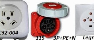
Types of protection for sockets
XXI CENTURY Candy Fudge Scented water
266 ₽ More details
Video baby monitor Motorola MBP36S (white)
12900 ₽ More details
T-shirts for boys
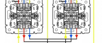
Connecting a two-gang switch
Before making the connection, you must first strip the ends of the wires by 1-1.5 centimeters to ensure good contact with the terminals. If the wires are powerful, multi-core, at this stage you need to press off their ends.
A switch with two keys should have three wires. One of them is input - phase, and the other two are output, which will supply voltage directly to the lamp itself.
The neutral wire and grounding, as already mentioned, are connected directly to the light source (to the light bulbs, or more precisely to their contacts).
After this, you need to find the phase wire and the entrance to it (unlike the outputs, there is only one). Look at the switch, previously freed from the top casing. At least one arrow must be drawn on it. It usually indicates where the phase will come from and where it will go. Near the base of the arrow, the phase wire should have an entrance.
Operation of a two-button switch
As a rule, in such switches the terminals for the phase input are marked with the symbol “L”, in turn, the terminals for the output cables are marked with arrow symbols.
To accurately find the phase, use a special device. And if it is not there, you can determine this experimentally by temporarily connecting a chandelier or lamp.
You need to alternately connect one wire to the other two using pliers in pairs (not simultaneously!). That is, you select one wire and connect it first to one of the remaining ones, then to the other. This wire, from which first one or another group of lamps (luminaires) will light up, is the phase.
When the phase is found, it can be connected to the input of the switch (this is the first wire that goes to the switch), and the other two wires - to the two output terminals, respectively (these are the second and third wires that go to the switch). Next, all that remains is to insulate the dangerous places on the wires and insert the structure into the socket box, which should be screwed into a place prepared in advance for this.
Afterwards, all that remains is to install the accessories and you can check the device in operation.
To better understand the connection diagram, we suggest watching the video below, which describes in detail and shows examples of the connection diagram of a two-key switch:
Illuminated switches
Such switching devices allow you to keep your walls clean. Quite often you have to turn on the light at night when everything is dark. When you try to feel the switch key in the dark, your hand often hits the wall instead of the key and gets dirty. As a result, abrasions form on the wall surface around the switching device.
Since the price difference is negligible, using an illuminated switch becomes a priority. However, many buyers still choose classic models. Why is this happening?
This situation arises due to the fact that various rumors and “legends” about the negative aspects of backlighting are spread via the Internet:
- Such types of switching elements consume electricity in greater quantities than established by regulations.
Some of this information can be considered reliable. When connecting backlit switches to an electrical network, the illuminated element consumes approximately 1 W of energy. By the end of a full month, this figure becomes equal to 0.5-0.7 kW/hour. Therefore, 3-5 rubles. You will need to pay for the convenience and comfort of connected lighting.
Today, this horror story is losing its relevance over time due to the insignificance of additional costs.
Graphic symbols in electrical diagrams
Regarding graphic symbols in electrical circuits, GOST 2.702-2011 refers to three other GOSTs:
- GOST 2.709-89 “ESKD. Conventional designations of wires and contact connections of electrical elements, equipment and sections of circuits in electrical circuits.”
- GOST 2.721-74 “ESKD. Conditional graphic designations in schemes. Designations for general use"
- GOST 2.755-87 “ESKD. Conventional graphic symbols in electrical diagrams. Switching and contact connection devices."
Conventional graphic symbols (UGO) of automatic circuit breakers, switches, contactors, thermal relays and other switching equipment that is used in single-line diagrams of electrical panels are defined in GOST 2.755-87.
However, there is no designation for RCDs and difavtomats in GOST. I think it will soon be reissued and the RCD designation will be added. In the meantime, each designer depicts an RCD according to his own taste, especially since GOST 2.702-2011 provides for this. It is enough to provide the UGO designation and its explanation in the explanations of the diagram.
In addition to GOST 2.755-87, to complete the circuit, you will need to use images from GOST 2.721-74 (mainly for secondary circuits).
All designations of switching devices are based on four basic images:
using nine functional features:
| Name | Image |
| 1. Contactor function | |
| 2. Switch function | |
| 3.Disconnector function | |
| 4. Switch-disconnector function | |
| 5. Automatic triggering | |
| 6. Travel or limit switch function | |
| 7. Self-return | |
| 8. No self-return | |
| 9. Arc suppression | |
| Note: The designations given in paragraphs. 1 - 4, 7 - 9, are placed on fixed contacts, and the designations in paragraphs. 5 and 6 - on moving contacts. |
Basic graphic symbols used in single-line diagrams of electrical panels:
| Name | Image |
| Circuit breaker (automatic) | |
| Load switch (switch) | |
| Contactor contact | |
| Thermal relay | |
| RCD | |
| Differential automatic | |
| Fuse | |
| Automatic switch for motor protection (circuit breaker with built-in thermal relay) | |
| Load switch with fuse (switch with fuse) | |
| Current transformer | |
| Voltage transformer | |
| Electric energy meter | |
| A frequency converter | |
| Normally closed contact of a push-button switch without self-reset with the control element opening and returning automatically | |
| Normally closed contact of a push-button switch without self-reset with opening and return of the control element by pressing the button a second time | |
| Normally closed contact of a push-button switch without self-reset with opening and return of the control element by pulling the button | |
| Normally closed contact of a push-button switch without self-reset with opening and returning of the control element via a separate drive (for example, pressing a reset button) | |
| Normally closed contact with delay when activated | |
| Normally closed contact with delay during return | |
| Normally closed contact with delay during operation and return | |
| Normally closed contact with delay when activated | |
| Normally closed contact with delay during return | |
| Normally closed contact with delay during operation and return | |
| Contactor coil, general designation for relay coil | |
| Impulse relay coil | |
| Photo relay coil | |
| Timing relay coil | |
| Motor drive | |
| Lighting lamp, light indication (light bulb) | |
| A heating element | |
| Plug connection (socket): socket pin | |
| Arrester | |
| Surge suppressor (SPD), varistor | |
| Dismountable connection (terminal) | |
| Ammeter | |
| Voltmeter | |
| Wattmeter | |
| Frequency meter |
The designations of wires and busbars in electrical panels are determined by GOST 2.721-74.
| Name | Image |
| Electrical communication line, wires, cables, buses, group communication line | |
| The protective conductor (PE) may be shown as a dashed line | |
| Graphic branching (merging) of group communication lines | |
| Crossing of electrical communication lines, group communication lines of electrically not connected wires, cables, tires, not electrically connected | |
| Electrical communication line with one branch | |
| Electrical communication line with two branches | |
| Bus (if it is necessary to graphically separate electrical communication lines from the image) | |
| Branch bus | |
| Buses graphically intersecting and not electrically connected | |
| Branches (tap-offs) from the bus |
Designation of switches in the drawings
All switches are schematically depicted as a circle with a line on the top. One hook located at the top of the dash indicates a single-gang open type switch. Two hooks correspond to a two-gang switch. An icon with three hooks indicates a switch with three keys. (Figures 1,2)
In the case where a perpendicular strip is placed above the main line, this indicates a switch design intended for hidden installation (Figure 3). One, two or three lines correspond to a one-, two- or three-key switch. If the circle is completely filled in black, it is an image of a moisture-resistant open type switch.
Figure 4 shows a circle intersected by a line with dashes located at the ends. Thus, pass-through switches in two positions are indicated on electrical diagrams. The circuit mirrors two ordinary switches. The number of perpendicular lines indicates the number of keys. The designation of moisture-resistant switches appears as a filled circle.
Figures 5, 6 and 7 show switches arranged together with receptacles in one block. This placement significantly saves space and facilitates installation. To connect, you only need one wire, laid in a single groove.
Figure 5 shows a regular switch connected to a standard outlet. The entire unit is designed for hidden installation. The next option (Figure 6) is more complex. It includes a grounded socket, as well as a one- and two-gang switch. Figure 7 shows a block consisting of two conventional switches and one socket.
Useful tips
- Calculate in advance the required (sufficient) cross-section and length of the wires depending on the power of the light sources. The cross-section cannot be less than one and a half square millimeters.
- In addition to the distribution box, it is also recommended to purchase an additional protective device that will protect against short circuits and overloads in the electrical network.
- Choose terminal switches rather than those with screw-in screws, as the first connection option is stronger and more durable: the screws will need to be tightened after a while.
- You can adjust the lighting using a single-key device! But for this, additional equipment is purchased and installed - the so-called dimmer.
- If you install a similar structure to illuminate a bathroom or other damp place, do not mount the switch indoors under any circumstances.
- Note: if the switch is modular, then there is always another one near the input terminal. These two terminals must be connected to each other with a separate wire.
- All connections and connections are strictly prohibited outside special junction boxes. And in the case of complicated environmental conditions, additional protection must be made (for example, from water, humidity, ingress of other solid and liquid substances).
- If you install a switch, for example, for a toilet, then one of the keys can turn on the light in this room, and the other can turn on the hood.
Connecting a switch that controls the light with two keys is not difficult if you strictly follow the instructions given above. Read all the instructions and useful tips first so that you don’t miss anything, then everything will work out!
Basic nuances when connecting
Switches belong to the category of functional interior elements, and the choice of connection location must be approached very carefully.
Using the device should be comfortable and completely safe.
Currently, there are several basic nuances that must be taken into account when connecting a light switch in a residential area:
- installation is carried out taking into account the average height of a person, so the optimal height is 80 cm from the floor level;
- access to the switch should not be blocked or blocked, and the optimal distance from interior items and the door jamb is 100 mm;
- switches for controlling light in a sanitary unit, storage room and hallway are most often installed in the corridor.
Particular attention is paid to switches for additional lighting. They can be installed in almost any area, and the main criterion for choosing a place for installation is compliance with the interior design. In the bathroom and kitchen, as well as in other rooms characterized by high humidity levels, switches with rubberized or reliable plastic casings are installed
In the bathroom and kitchen, as well as in other rooms characterized by high levels of humidity, switches with rubberized or reliable plastic casings are installed.
How the output contacts are connected
The presence of a large number of symbols on the contacts of multi-key electrical switches causes certain difficulties with their connection. It is difficult for an inexperienced user without measuring equipment to determine which of the conductors is responsible for turning on a specific light bulb in a chandelier or one of the groups of luminaires. In this situation, you have to act by trial or error.
The procedure for each type of switch can be represented as the following algorithm:
- with a single-key version, the switch has L and L1 - this means that only one outlet conductor is connected to the output;
- in a two-key analogue, they will have to be connected alternately to each of the output terminals, and watch which of the illuminators lights up;
- based on experimental data, the required contacts are selected under the designations L1 and L2;
- in a three-key model, the possibilities expand: you will have to go through the connection order many times (the number of combinations of three options is 6).
It is possible to simplify the last operation if you alternately connect “unidentified” outlet conductors with the phase wire and observe which light bulbs, groups or lamps light up.
Normative base
On the territory of the Russian Federation, the designation of a group or single sockets and switches on design drawings is subject to the following documents:
- GOST 21.614-88. Subsection “Images of conventional graphic electrical equipment and wiring” from the section on the system of design and construction documentation;
- GOST 21.210-2014. Electrical devices, according to the standard, can be depicted in the form of standard symbols;
- IEC 60027. A standard adopted by the International Electrotechnical Commission, according to which wiring in Russian buildings must meet international requirements.
The regulatory documentation notes the specifics of creating symbols for power lines and auxiliary devices on the working diagram.