The heat generator of Yu. S. Potapov is very similar to the vortex tube of J. Ranquet, invented by this French engineer back in the late 20s of the XX century. While working on improving cyclones for purifying gases from dust, he noticed that the gas stream leaving the center of the cyclone has a lower temperature than the source gas supplied to the cyclone. Already at the end of 1931, Ranke submitted an application for the invented device, which he called a “vortex tube”. But he managed to obtain a patent only in 1934, and then not in his homeland, but in America (US Patent No. 1952281.)
Scope of application
| Illustration | Description of application |
| Heating. Equipment that converts the mechanical energy of water movement into heat is successfully used in heating various buildings, from small private buildings to large industrial facilities. By the way, in Russia today you can already count at least ten settlements where centralized heating is provided not by traditional boiler houses, but by gravity generators. | |
| Heating of running water for domestic use. The heat generator, when connected to the network, heats the water very quickly. Therefore, such equipment can be used to heat water in an autonomous water supply system, in swimming pools, bathhouses, laundries, etc. | |
| Mixing immiscible liquids. In laboratory conditions, cavitation units can be used for high-quality mixing of liquid media with different densities until a homogeneous consistency is obtained. |
Integration into the heating system of a private home
In order to use a heat generator in a heating system, it must be installed into it. How to do this correctly? In fact, there is nothing complicated about it.
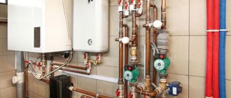
Scheme for introducing a vortex heat generator into the heating system of a country house or apartment - apart from the presence of a pump, there are no special differences from installing a conventional boiler
In front of the generator (marked 2 in the figure) a centrifugal pump (1 in the figure) is installed, which will supply water with a pressure of up to 6 atmospheres. After the generator, an expansion tank (6 in the figure) and shut-off valves are installed.
Advantages of using cavitation heat generators
Advantages of a vortex source of alternative energy
Economical. Thanks to the efficient consumption of electricity and high efficiency, the heat generator is more economical compared to other types of heating equipment.
Small dimensions compared to conventional heating equipment of similar power. A stationary generator, suitable for heating a small house, is twice as compact as a modern gas boiler.
If you install a heat generator in a regular boiler room instead of a solid fuel boiler, there will be a lot of free space left.
Low installation weight. Due to its light weight, even large high-power installations can be easily placed on the floor of the boiler room without building a special foundation. There are no problems at all with the location of compact modifications.
The only thing you need to pay attention to when installing the device in a heating system is the high noise level. Therefore, installation of the generator is possible only in non-residential premises - in a boiler room, basement, etc.
The device has a small number of mechanically moving elements, and there is no complex electronics at all
Therefore, the likelihood of device failure, in comparison with gas or even solid fuel boilers, is minimal
Simple design. The cavitation type heat generator is so simple that there is nothing to break in it.
The device has a small number of mechanically moving elements, and there are no complex electronics at all. Therefore, the likelihood of device failure, in comparison with gas or even solid fuel boilers, is minimal.
There is no need for additional modifications. The heat generator can be integrated into an existing heating system. That is, there is no need to change the diameter of the pipes or their location.
There is no need for water treatment. If a running water filter is needed for normal operation of a gas boiler, then by installing a cavitation heater, you don’t have to worry about blockages.
Due to specific processes in the working chamber of the generator, blockages and scale do not appear on the walls.
The operation of the equipment does not require constant monitoring. If solid fuel boilers need to be looked after, the cavitation heater operates in autonomous mode.
The operating instructions for the device are simple - just plug in the engine and, if necessary, turn it off.
Environmental friendliness. Cavitation installations do not affect the ecosystem in any way, because the only energy-consuming component is the electric motor.
Installation YUSMAR-M
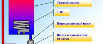
In the YUSMAR-M installation, a vortex heat generator complete with a submersible pump is placed in a common vessel-boiler with water (see Figure 3) so that heat loss from the walls of the heat generator, as well as the heat generated during operation of the pump electric motor, also occurs to heat the water, and not get lost. The automation periodically turns the heat generator pump on and off, maintaining the water temperature in the system (or the air temperature in the heated room) within the limits specified by the consumer. The outside of the boiler vessel is covered with a layer of thermal insulation, which simultaneously serves as sound insulation and makes the noise of the heat generator almost inaudible, even directly next to the boiler.
"USMAR" installations are designed to heat water and supply it to autonomous water heating systems of residential premises, industrial and administrative buildings, as well as to showers, baths, kitchens, laundries, sinks, for heating dryers of agricultural products, pipelines of viscous petroleum products to prevent them freezing in cold weather and other industrial and domestic needs.
Figure 4. Photo of the thermal installation "YUSMAR-M"
YUSMAR-M installations are powered by an industrial three-phase 380 V network, are fully automated, are supplied to customers complete with everything necessary for their operation and are installed by the supplier on a turnkey basis.
All these installations have the same boiler vessel (see Figure 4), into which vortex tubes and motor pumps of different power are immersed, choosing the most suitable for a particular customer. Dimensions of the boiler vessel: diameter 650 mm, height 2000 mm. These installations, recommended for use both in industry and in everyday life (for heating residential premises by supplying hot water to water heating radiators), have technical specifications TU U 24070270.001-96 and a certificate of conformity ROSS RU. MHZ. S00039.
YUSMAR installations are used in many enterprises and private households; they have received hundreds of praising reviews from users. Currently, thousands of YUSMAR heating installations are successfully operating in the CIS countries and a number of other countries in Europe and Asia.
Their use is especially beneficial in areas where gas pipelines have not yet reached and where people are forced to use electricity, which is becoming more and more expensive every year, to heat water and heat their premises.
Figure 5. Connection diagram of the thermal installation “YUSMAR-M” to the water heating system: 1 - heat generator “YUSMAR”; 2 - circular pump; 3-control panel; 4 - thermostat.
YUSMAR heating installations allow you to save a third of the electricity that is necessary for heating water and heating premises using traditional electric heating methods.
Two schemes for connecting consumers to the YUSMAR-M heat installation have been developed: directly to the boiler (see Figure 5) - when the hot water flow in the consumer’s system is not subject to sudden changes (for example, for heating a building), and through a heat exchanger (see Figure 6 ) - when the consumer’s water consumption fluctuates over time.
YUSMAR heating installations do not have parts that heat up to temperatures above 100°C, which makes these installations especially acceptable from the point of view of fire safety and safety regulations.
Figure 6. Connection diagram of the thermal installation “YUSMAR-M” to the shower room: 1-heat generator “YUSMAR”; 2 - circular pump; 3- control panel; 4 - temperature sensor, 5 - heat exchanger.
Used Books:
Yu.S. Potapov, L.P. Fominsky, S.Yu. Potapov - “Rotation energy” - 01/01/2008
Kinds
The main task of a cavitation heat generator is the formation of gas inclusions, and the quality of heating will depend on their quantity and intensity. In modern industry, there are several types of such heat generators, differing in the principle of producing bubbles in the liquid. The most common are three types:
- Rotary heat generators - the working element rotates due to an electric drive and produces fluid turbulence;
- Tubular - change pressure due to a system of pipes through which water moves;
- Ultrasonic - the heterogeneity of the liquid in such heat generators is created due to low-frequency sound vibrations.
In addition to the above types, there is laser cavitation, but this method has not yet found industrial implementation. Now let's look at each type in more detail.
Rotary heat generator
It consists of an electric motor, the shaft of which is connected to a rotor mechanism designed to create turbulence in the liquid. A special feature of the rotor design is the sealed stator, in which heating occurs. The stator itself has a cylindrical cavity inside - a vortex chamber in which the rotor rotates. The rotor of a cavitation heat generator is a cylinder with a set of depressions on the surface; when the cylinder rotates inside the stator, these depressions create heterogeneity in the water and cause cavitation processes to occur.
Rice. 3: Rotary type generator design
The number of recesses and their geometric parameters are determined depending on the model of the vortex heat generator. For optimal heating parameters, the distance between the rotor and stator is about 1.5 mm. This design is not the only one of its kind; over the long history of modernizations and improvements, the rotor-type working element has undergone a lot of transformations.
One of the first effective models of cavitation converters was the Griggs generator, which used a disk rotor with blind holes on the surface. One of the modern analogues of disk cavitation heat generators is shown in Figure 4 below:
Rice. 4: disk heat generator
Despite the simplicity of the design, rotary-type units are quite complex to use, as they require precise calibration, reliable seals and adherence to geometric parameters during operation, which makes their operation difficult. Such cavitation heat generators are characterized by a fairly low service life - 2 - 4 years due to cavitation erosion of the housing and parts. In addition, they create a fairly large noise load during operation of the rotating element. The advantages of this model include high productivity - 25% higher than that of classic heaters.
Tubular
A static heat generator has no rotating elements. The heating process in them occurs due to the movement of water through pipes that taper in length or due to the installation of Laval nozzles. Water is supplied to the working element by a hydrodynamic pump, which creates a mechanical force of the fluid in a narrowing space, and when it passes into a wider cavity, cavitation vortices occur.
Unlike the previous model, tubular heating equipment does not make much noise and does not wear out as quickly. During installation and operation, you do not need to worry about precise balancing, and if the heating elements are destroyed, their replacement and repair will cost much less than rotary models. The disadvantages of tubular heat generators include significantly lower productivity and bulky dimensions.
Ultrasonic
This type of device has a resonator chamber tuned to a certain frequency of sound vibrations. A quartz plate is installed at its input, which produces oscillations when electrical signals are supplied. The vibration of the plate creates a wave effect inside the liquid, which reaches the walls of the resonator chamber and is reflected. During the return movement, the waves encounter direct vibrations and create hydrodynamic cavitation.
Rice. 5: Operating principle of ultrasonic heat generator
Next, the bubbles are carried away by the water flow through the narrow inlet pipes of the thermal installation. When moving into a wide area, the bubbles collapse, releasing thermal energy. Ultrasonic cavitation generators also have good performance characteristics, since they do not have rotating elements.
History of creation
French scientists then treated this invention with distrust and ridiculed the report of J. Ranquet, made in 1933 at a meeting of the French Physical Society. For, according to these scientists, the work of the vortex tube, in which the air supplied to it was divided into hot and cold flows like a fantastic “Maxwell’s demon,” contradicted the laws of thermodynamics. Nevertheless, the vortex tube worked and later found wide application in many fields of technology, mainly for producing cold.
For us, the most interesting work is the work of Leningrader V. E. Finko, who drew attention to a number of paradoxes of the vortex tube, developing a vortex gas cooler to obtain ultra-low temperatures. He explained the process of gas heating in the near-wall region of the vortex tube by the “mechanism of wave expansion and compression of gas” and discovered infrared radiation of gas from its axial region, which has a band spectrum, which later helped us understand the operation of Potapov’s vortex heat generator.
In a Ranke vortex tube, the diagram of which is shown in Figure 1, a cylindrical pipe 1 is connected at one end to a volute 2, which ends with a nozzle input of rectangular cross-section, which supplies compressed working gas into the pipe tangentially to the circumference of its inner surface. At the other end, the snail is closed by a diaphragm 3 with a hole in the center, the diameter of which is significantly smaller than the internal diameter of pipe 1. Through this hole, a cold gas flow exits pipe 1, which is divided during its vortex movement in pipe 1 into cold (central) and hot (peripheral) parts. The hot part of the flow adjacent to the inner surface of pipe 1, rotating, moves to the far end of pipe 1 and leaves it through the annular gap between its edge and the adjusting cone 4.
Figure 1. Ranke vortex tube: 1-tube; 2- snail; 3- diaphragm with a hole in the center; 4-adjustment cone.
A complete and consistent theory of the vortex tube still does not exist, despite the simplicity of this device. “Basically” it turns out that when a gas spins in a vortex tube, under the influence of centrifugal forces it is compressed at the walls of the pipe, as a result of which it heats up here, just as it heats up when compressed in a pump. In the axial zone of the pipe, on the contrary, the gas experiences a vacuum, and here it cools and expands. By removing gas from the near-wall zone through one hole, and from the axial zone through another, the separation of the initial gas flow into hot and cold flows is achieved.
Liquids, unlike gases, are practically incompressible. Therefore, for more than half a century, no one even thought of feeding water into a vortex tube instead of gas or steam. And the author decided on a seemingly hopeless experiment - he fed water from the water supply into the vortex tube instead of gas.
To his surprise, the water in the vortex tube divided into two streams having different temperatures. But not hot and cold, but hot and warm. Because the temperature of the “cold” flow turned out to be slightly higher than the temperature of the source water supplied by the pump to the vortex tube. Careful calorimetry showed that such a device produces more thermal energy than is consumed by the electric motor of the pump supplying water to the vortex tube.
This is how Potapov’s heat generator was born.
Tips you should listen to
Diagram of a heat gun.
- Be sure to protect the Potapov vortex heat generator by painting all surfaces.
- During operation, its internal parts will be in a very aggressive environment caused by cavitation processes. Therefore, try to make both the body and everything that is in it from thick material. Don't skimp on hardware.
- Make several versions of lids with different inlet holes. Then it will be easier to select their diameter in order to obtain high performance.
- The same applies to the vibration damper. It can also be modified.
Build a small laboratory stand where you will test all the characteristics. To do this, do not connect consumers, but loop the pipeline to the generator. This will simplify its testing and selection of the necessary parameters. Since complex instruments for determining the efficiency factor at home can hardly be found, the following test is proposed.
Turn on the vortex heat generator and note the time when it heats the water to a certain temperature. It is better to have an electronic thermometer, it is more accurate. Then make changes to the design and run the experiment again, monitoring the temperature increase. The more the water heats up at the same time, the more preference will need to be given to the final version of the installed improvement in the design.
A number of advantages and disadvantages
The high-performance vortex heat generator is presented in a large number of designs precisely due to the fact that such devices are characterized by a number of significant advantages, including:
Like any other alternative heat source, a vortex cavitation heat generator is not widely popular, despite its fairly high efficiency. Accordingly, one of the main disadvantages is the high cost, which is partly due to the insignificant level of distribution of such equipment, despite the fact that today manufacturers offer various models.
Features of the models
The vortex cavitation heat generator exists in different designs. Today, the most common devices are water-based, that is, liquid acts as a coolant.
But it is also possible to purchase a solid fuel unit, the output of which produces a gaseous mixture of flue gas and air.
The high-performance vortex solid fuel heat generator is distinguished by the ability to burn wood with high humidity (up to 65%). Accordingly, when choosing, the purpose of the unit and the expected load are taken into account, since there are versions with different levels of thermal power. Depending on the size of the object to be served, a suitable device is selected.
In the case of solid fuel equipment, it is important to take into account the rate of fuel consumption, the size of the loading chamber and the type of fuel loading
You can select a vortex heat generator of different types according to the level of thermal power, or you can pay attention to the clause in the accompanying documentation about how much volume is allowed to be heated. The weight and overall dimensions of the equipment are also important.
Review of models of different designs
Watch a video about the product:
If you choose a solid fuel version, then in this case we consider more efficient equipment with a thermal power of 250 to 700 kW. For example, models TVV-R-250, TVV-R-500, TVV-R-700. All of them involve manual loading of fuel. But more powerful versions consume more fuel. If the 250 model consumes 120 kg/hour, then the 700 version consumes about 340 kg/hour. There are much more efficient devices with a thermal power of 2,500 kW. If you plan to use such vortex heat generators, then their price will be noticeably higher.
The smaller the overall dimensions of such equipment, the simpler its operation will be. For example, there are completely autonomous devices with automatic control. In this case, the user does not need to participate in the process. But when using some versions of solid fuel heat generators, it is impossible to do without the participation of a trained operator to load fuel, since the unit data assumes manual supply of wood.
Today, there are different versions of such equipment with fully automated execution, including preset temperature conditions. Considering that units of this kind are completely safe, both from the point of view of environmental friendliness and from the point of view of fire safety, there is no need for their constant monitoring.
Thus, to organize a heating system and hot water supply, it is not always necessary to resort to standard solutions. In practice, it turns out that when using thermal installations based on vortex heat generators, significant savings are noted in comparison with other types of heating systems.
As a result, you can get not only high-performance equipment, but also save money during its operation. Despite the rather high cost of such units, their further operation fully pays off, and you won’t have to wait too long for this, since in some cases the payback period reaches 6 months.
It’s rare that an owner doesn’t try to save on heating or the consumption of other benefits, which become more and more expensive every year. To make the heating system of a residential or industrial premises economical, many people resort to various schemes and methods for generating thermal energy. One of the devices suitable for these purposes is a cavitation heat generator.
Vortex thermal generator (VTG)
The serially produced vortex heat generator "VTG" is a standard asynchronous electric motor 3000 rpm, supply voltage 380 V, mounted on the same frame with a working element that converts mechanical energy into thermal energy.
When installing and connecting “VTG”, approvals from energy authorities are not required, since electrical energy is used to rotate the electric motor, and not to directly heat the coolant. They are fully prepared for connection to a new or existing heating system, and the design and dimensions of the heating unit simplify its placement and installation in the heating unit. The high efficiency of vortex heat generators makes it possible, when selecting large-scale power, to apply a standard of 1 kW of installed electric motor power per 15-20 m2 of area (for a volume of 45-50 m3), while for other types of thermal installations a standard of 1 kW of thermal energy per 10 m2 of area is applied . Based on the enlarged standard, thermal installations must heat conventional typical residential, domestic, cultural and entertainment premises, premises for industrial and economic purposes, etc.
Any temperature regime can be maintained in heated rooms. For example, for residential premises - 20-22°C, industrial premises - 15-18°C, warehouses - 8-12°C. Temperature regulation is carried out by setting the temperature range of the coolant. When the coolant is heated to the specified maximum temperature, the heating unit is turned off, when the coolant is cooled to the minimum set temperature, it is turned on.
TECHNICAL REQUIREMENTS
Functional parameters:
- According to operating conditions, heat generators are classified as devices operating without supervision.
- Heat generators must be operational when using water as a coolant in accordance with GOST 2874 without additional cleaning or filtration.
- The minimum operating pressure of water at the entrance to the heating system is 0.1 MPa, the maximum is 0.6 MPa.
- The average electricity consumption is 10 - 30% of the rated power of the VTG.
| Installation name | Electric motor power, kW | Weight, kg. | Heating capacity, kcal/hour. (no less) | Heated volume, m3/area, m2 | Dimensions length, width, height, mm. | Coolant temperature, C° |
| VTG-5 | 5 | 95 | 4650 | 250/90 | 570 x 290 x 410 | 95 |
| VTG- 7.5 | 7,5 | 110 | 6350 | 350/120 | 590 x 296 x 420 | |
| VTG-7.5 with Grundfos engine | 7,5 | 110 | 7300 | 350/130 | 590 x 296 x 420 | |
| VTG-11 | 11 | 140 | 9300 | 500/170 | 660 x 315 x 420 | |
| VTG-15 | 15 | 190 | 12650 | 700/240 | 755 x 360 x 455 | |
| VTG-18 | 18 | 220 | 15150 | 700/240 | 900 x 520 x 540 | |
| VTG -22 | 22 | 240 | 18600 | 1000/350 | 820 x 505 x 520 | |
| VTG-30 | 30 | 320 | 25300 | 1400/470 | 1250 x 650 x 700 | |
| VTG-37 | 37 | 360 | 31200 | 1700/580 | 1350 x 650 x 700 | |
| VTG-45 | 45 | 390 | 37900 | 2000/670 | 1350 x 650 x 700 | |
| VTG-55 | 55 | 450 | 46350 | 2500/840 | 1640 x 600 x 700 | |
| VTG-75 | 75 | 675 | 63200 | 3400/1150 | 1640 x 646 x 740 | |
| Installation at 220V | ||||||
| VTG-2.2 | 2,2 | 35 | 1800 | 90/30 | 430 x 270 x 270 | 95 |
Advantages of VTG when used in heating and hot water systems:
- Does not require approval from Energonadzor and boiler inspection.
- Minimal maintenance (check generator bearings and seals once every 6 months). Ensured by high technologies for manufacturing these units.
- Economical:
- no costs for laying heating mains and minimizing heat losses;
- no costs for water treatment (water quality, the degree of its contamination in the heating system and mineralization do not affect the operation of the heater);
- thanks to heating technology, scale does not appear in the heating system;
- there is no need to create fuel reserves and ensure their safety (if gas, coal, firewood, and oil products are used as heating fuel).
- Safe to use and environmentally friendly:
- the operation of the heat generator eliminates the use of environmental pollutants (gas, coal, firewood, diesel fuel) and, accordingly, eliminates the release of combustion products and air decay. The possibility of explosion or fire is excluded;
- the use of modern safety control devices completely eliminates the uncontrolled increase in temperature and pressure in the heating system.
- Easy to install and maintain:
- for installation, it is enough to connect the supply and return pipes of the heat generator to the corresponding pipes of the heating system;
- ease of maintenance. The heating process and control of the heating system are carried out using an automatic control unit. No special training of operating personnel is required.
- Uuniversal in use, can be used:
- for heating, including in systems with heated floors;
- for hot water supply systems (DHW);
- both in a new and in an existing heating and hot water system;
- for liquids for various purposes;
- Autonomous.
We carry out design and installation of installations. Contact us in the CONTACTS section or fill out the Questionnaire. We will be happy to answer your questions
| Share link to page: |
Heater structure and operating principle
Cavitation heating is characterized by the formation of bubbles from steam in the working fluid. As a result of this action, the pressure gradually decreases due to the high flow rate. It should be noted that the necessary vaporization is set by special radiation of laser pulses or acoustics set by certain sounds. Closed air regions mix with the water mass, after which they enter a high-pressure zone, where they open and emit the expected shock wave.
Cavitation-type equipment differs in the way it operates. Schematically it looks like this:
- The water flow moves through the cavitator, in which the working pressure entering the working tank is ensured using a circulation pump.
- Next, in such containers the speed and, accordingly, the pressure of the liquid increases through tubes installed according to the drawings.
- The flows, reaching the central part of the chamber, mix, resulting in cavitation.
- As a result of the described process, the steam bubbles do not increase in size, and there is no interaction between them and the electrodes.
- After this, the water moves to the opposite part of the container and returns to complete a new circle.
- Heating is provided by the movement and expansion of the liquid at the exit from the nozzle.
From the operation of the vortex installation it is clear that its design is uncomplicated and simple, but at the same time it provides quick and profitable heating of the room.
Advantages of heat generators when used for heating
The most obvious advantage of heat generators is fairly simple maintenance, despite the possibility of free installation without requiring special permission from power grid employees. It is enough to check the rubbing parts of the device – bearings and seals – once every six months. At the same time, according to suppliers, the average guaranteed service life is up to 15 years or more.
Potapov's heat generator is completely safe and harmless to the environment and the people using it. Environmental friendliness is justified by the fact that during the operation of a cavitation heat generator, emissions of harmful products into the atmosphere from the processing of natural gas, solid fuel materials and diesel fuel are excluded. They are simply not used.
The work is powered by the electrical network. The possibility of fire due to lack of contact with open flame is excluded. Additional security is provided by the device’s instrument panel; it provides total control over all processes of temperature and pressure changes in the system.
Economic efficiency when heating a room with heat generators is expressed in several advantages. Firstly, there is no need to worry about the quality of water when it plays the role of a coolant. There is no need to think that it will harm the entire system just because of its poor quality. Secondly, there is no need to make financial investments in the arrangement, laying and maintenance of heating routes. Thirdly, heating water using physical laws and the use of cavitation and vortex flows completely eliminates the appearance of calcium stones on the internal walls of the installation. Fourthly, spending money on transportation, storage and purchase of previously necessary fuel materials (natural coal, solid fuel materials, petroleum products) is eliminated.
The undeniable advantage of heat generators for home use is their exceptional versatility. The range of applications of heat generators in everyday life is very wide:
- as a result of passing through the system, water is transformed, structured, and pathogenic microbes die under such conditions;
- You can water the plants with water from the heat generator, which will promote their rapid growth;
- the heat generator is capable of heating water to a temperature above the boiling point;
- the heat generator can work in conjunction with existing systems or be built into a new heating system;
- the heat generator has long been used by people aware of it as the main element of the heating system in homes;
- the heat generator easily and inexpensively prepares hot water for use in household needs;
- The heat generator can heat liquids used for various purposes.
A completely unexpected advantage is that the heat generator can even be used for oil refining. Due to the uniqueness of the development, the vortex installation is capable of liquefying heavy oil samples and carrying out preparatory measures before transportation to oil refineries. All of these processes are carried out at minimal cost.
It should be noted that heat generators are capable of completely autonomous operation. That is, the intensity mode of its operation can be set independently. In addition, all designs of the Potapov heat generator are very simple to install. There is no need to involve service workers; all installation operations can be done independently.
About the public organization VTG
All-Russian public organization of disabled people to promote the development of television for the deaf “All-Russian Television of the Deaf” - briefly “VTG”, developed on the initiative of a group of people with hearing disabilities, and officially registered by the Ministry of Justice of the Russian Federation on February 13, 2022 and will continue to interact with the Ministry of Digital Development and Communications and mass communications of the Russian Federation and with Roskomnadzor to control any individuals and organizations on websites, YouTube, social networks or in any sources where deaf people themselves appear in videos, including sign language interpreters, in order to prevent distortion, provocations, propaganda, false information, etc.
LLC VTG was created on the basis of their common interests to provide and protect the rights of common interests, provide people with hearing disabilities with equal opportunities with other citizens, solve the problems of social integration of people with hearing disabilities, achieve common goals, including the development and protection of rights and freedom MASS MEDIA. The organization is an all-Russian voluntary public association based on the membership of fully capable citizens with hearing disabilities and their legal representatives and legal entities - public associations.
VTG LLC is developing planned development for the comfortable convenience of our VTG members in various areas on various issues, complaints, proposals for providing and assisting the hearing impaired. At the moment, LLC VTG has its own media institution VTG, working in two directions of information in Russian Language and subtitling:
1) TV channel VTG with leading RJY and subtitles;
2) VTG information portal on the website and even a convenient mobile application “VTG”.
The media institution VTG TV channel was created for deaf television viewers for the convenience and comfort of watching the channel’s television programs in the form of accompaniment by presenters on RZH for an understandable and meaningful daily television channel with full-scale information, consisting of socio-cultural, sports, educational, entertainment and other information material. And even full-length and short films and series with the participation of hearing impaired people as actors, including animated cartoons for children with hearing impairment, in their native Russian Sign Language (RSL) and with subtitling for late-deafened and hearing people. The program will also feature general information stories reflecting events in the lives of deaf people in Russia, the CIS countries and abroad. In addition, the channel will feature domestic and foreign films, series with the participation of a hearing actor, as well as cartoons accompanied by subtitles. Currently, ORT, RTR and other Russian channels have subtitling, but unfortunately, not everyone understands the essence of the subtitling text. Official statistics indicate that in Russia there are about 9 million people with hearing loss. Such a huge number of Russians with hearing loss have the right to receive television information equally with other citizens. These rights are enshrined in the Constitution and the Law on Persons with Disabilities.
Establishment of the VTG information portal for the purpose of convenient and comfortable viewing on the website and in mobile applications, accompanied by presenters on RSL and with the possibility of providing a 24-hour online sign language interpreter for VTG members. The content of the information portal VTG intends to be informative, interesting and varied for people with hearing loss. Even on websites and mobile applications it will work in the form of a VTG video channel. We are going to tell you about the creativity of people with hearing impairments (after all, this in itself is an almost endless topic), about sports and other events, studios with interesting people - both deaf and hearing, as well as politicians and officials. In the future, famous personalities will be invited: actors, directors, artists.
VTG LLC will interact with various educational institutions to recommend educational directions for the development of our Organization and the VTG media institution, and it is also planned to create its own educational base in the form of training courses to prepare specialists for further professional career growth in film studios and television from among hearing people with proficiency in Russian language, including the hearing impaired.
Each of the deaf people has numerous hobbies and professional achievements, which will undoubtedly attract the attention of the widest development of the VTG organization. And someone will probably be interested in innovative educational programs for people with hearing loss and the problems of their professional careers.
Each member of the VTG will be able to receive answers to their letters, legal advice and consultations.
What is cavitation
Cavitation is a negative phenomenon that occurs due to a pressure difference in a liquid. When the water pressure drops to the value of the saturated vapor pressure, this leads to boiling. This is when the liquid partially turns into a vapor state, that is, bubbles form. When the pressure rises to a level above the saturated vapor value, the bubbles burst. As a result of the explosion, local pressure waves of up to 7 thousand bar occur. These pressure waves are called cavitation.
This also applies to the technology of insulating the roof from the inside with mineral wool. But in addition to vapor barrier, a hydrobarrier is also used.
- metal erosion;
- pitting corrosion;
- the appearance of vibrations.
The inventors of the cavitation generator claim that they were able to benefit from this negative phenomenon.
Do it yourself?
You can buy a ready-made cavitation heat generator, but it is unlikely to be possible to make this device yourself according to the drawings. At best, the result will be a noisy machine in which there will be no cavitation. In addition, before doing anything, you need to ask yourself the question: “Why?” There are many ways to heat your home:
- gas, solid fuel, electric boilers in tandem with water heating systems;
- electric heaters;
- PLEN systems;
- warm infrared floors;
- air conditioner;
- heat pumps or solar systems - if you want something exotic.
Don’t believe those who say that making cavitation heat generators with your own hands is easy and simple, spending two pennies. This is wrong. You will only waste your time and get nothing in return but disappointment.
Compared to a pitched roof, insulating the attic floor with mineral wool is a simpler process.
Here in the video below is an example of how a craftsman can make this device. Do you think it’s possible to heat anything with it?
Solid fuel stoves ITProm
E
An efficient and reliable heating stove, Russia, has proven itself to work on cheap fuel in the form of wood waste from furniture production, processing of wood raw materials, slabs and other solid fuel waste, including the cheapest coal.
The
volume of the combustion space is 1/4 cubic meter, which allows loading a sufficient amount of fuel and thereby ensuring long-term combustion and maintaining heat in heated rooms.
M
The maximum area of a heated room with an average ceiling height of 4-5 m is 1500 m2, which makes it possible to provide heat to small facilities, such as car services, sawmills, small furniture production, workshops, small workshops, farms, warehouses and other commercial facilities.
The
stove's furnace is lined with refractory fireclay bricks, which have high heat capacity and are resistant to temperature changes.
IN
Cast iron grates and a steel tray are installed at the bottom of the firebox.
The oven
is painted with heat-resistant paint and the joints are sealed with fire-resistant and impact-resistant sealant.
The
heat exchanger is made of high-strength, seamless cold-rolled steel pipes designed for use in boilers and ensuring efficient heat exchange when air passes through.
T
PROMA
stoves is sufficient for heating small production areas, such as furniture production, various kinds of workshops, greenhouses, livestock facilities, etc.
N
The cheapest operation of the
PROMA
will be where there is an abundance of wood waste, non-business wood, cheap brown coal, etc.
flammable materials. Regions
with wood processing industries, rich in forest raw materials and poorly gasified are the main consumers of stoves using wood waste and coal.
ABOUT
The main advantage of these stoves compared to other solid fuel stoves is their high thermal power,
up to 150 kW
, which allows heating fairly large areas, the presence of a gas-air heat exchanger, which can significantly increase the efficiency of heating rooms and a supply fan, which provides forced air supply to the heat exchanger of the stove and beyond , through air ducts directly into heated rooms.
PROMA ovens
Perfect for heating residential and domestic premises.
The thermal power of these stoves is sufficient to heat a residential building with an area of 300 to 1500 m2 .
The supply of warm air into the premises is provided by supply air ducts. These stoves are much more efficient than the wood-burning stoves that are widely used in our country, operating on the convection principle (stoves such as Potbelly stove, Buleryan, etc.). P.).
In these furnaces, heat from metal structures, pipes, etc. is transferred to cold air, which, when heated, flows around metal surfaces and passes through convection pipes, rises. Thus, air circulation occurs and the room is gradually warmed up. PROMA stoves
are installed outside the heated room, and warm air is supplied into the room through an air duct using a fan. The room quickly warms up and there is constant air circulation.
VTG drawings. Let's make a heat generator together with our own hands
This article describes how to make a heat generator on your own.
The operating principle of a static heat generator and the results of its research are described in detail. Recommendations for its calculation and selection of components are given.
The idea of creation
What to do if you don’t have enough money to purchase a heat generator? How to make it yourself? I will tell you about my own experience in this matter.
We got the idea to make our own heat generator after getting acquainted with various types of heat generators. Their designs seemed quite simple, but not fully thought out.
There are two known designs of such devices: rotary and static. In the first case, to create cavitation, as you might guess from the name, a rotor is used; in the second, the main element of the device is the nozzle. To make a choice in favor of one of the design options, let’s compare both designs.
Rotary heat generator
What is a rotary heat generator? In essence, this is a slightly modified centrifugal pump. That is, there is a pump housing (which in this case is a stator) with inlet and outlet pipes, and a working chamber, inside of which there is a rotor that acts as an impeller. The main difference from a conventional pump is the rotor. There are a great many designs of vortex heat generator rotors, and of course we will not describe them all. The simplest of them is a disk, on the cylindrical surface of which many blind holes of a certain depth and diameter are drilled. These holes are called Griggs cells, named after the American inventor who was the first to test a rotary heat generator of this design. The number and dimensions of these cells are determined based on the size of the rotor disk and the rotational speed of the electric motor driving it into rotation. The stator (aka heat generator housing), as a rule, is made in the form of a hollow cylinder, i.e. a pipe plugged on both sides with flanges. In this case, the gap between the inner wall of the stator and the rotor is very small and amounts to 1...1.5 mm.
It is in the gap between the rotor and stator that the water is heated. This is facilitated by its friction on the surface of the stator and rotor, during the rapid rotation of the latter. And of course, cavitation processes and turbulence of water in the rotor cells play a significant role in heating water. The rotor rotation speed is usually 3000 rpm with a diameter of 300 mm. As the rotor diameter decreases, it is necessary to increase the rotation speed.
It is not difficult to guess that, despite its simplicity, such a design requires quite high manufacturing precision. And it is obvious that rotor balancing will be required. In addition, we have to solve the issue of sealing the rotor shaft. Naturally, sealing elements require regular replacement.
From the above it follows that the resource of such installations is not so great. In addition to everything else, the operation of rotary heat generators is accompanied by increased noise. Although they have 20-30% greater productivity in comparison with static heat generators. Rotary heat generators are even capable of producing steam. But is this an advantage for a short service life (compared to static models)?
Static heat generator
The second type of heat generator is called static. This is due to the absence of rotating parts in the cavitator design. To create cavitation processes, various types of nozzles are used. The most commonly used is the so-called Laval nozzle
For cavitation to occur, it is necessary to ensure a high speed of fluid movement in the cavitator. For this, a conventional centrifugal pump is used. The pump builds up liquid pressure in front of the nozzle; it rushes into the nozzle opening, which has a significantly smaller cross-section than the supply pipeline, which ensures high speed at the nozzle exit. Due to the sharp expansion of the liquid at the exit of the nozzle, cavitation occurs. This is also facilitated by the friction of the liquid on the surface of the nozzle channel and the turbulence of the water that occurs when the jet suddenly pulls out of the nozzle. That is, water heats up for the same reasons
Heat generator design
It is more correct to talk about the efficiency of a heat generator - the ratio of the amount of thermal energy it generates to the amount of electrical or mechanical energy it consumes from the outside. But at first, researchers could not understand where and how excess heat was generated in these devices. It was even suggested that the law of conservation of energy was violated.
Figure 2. Diagram of a vortex heat generator: 1-injection pipe; 2- snail; 3- vortex tube; 4- bottom; 5- flow straightener; 6- fitting; 7- flow straightener; 8- bypass; 9- pipe.
The vortex heat generator, the diagram of which is shown in Figure 2, is connected by injection pipe 1 to the flange of a centrifugal pump (not shown in the figure), supplying water under a pressure of 4-6 atm. Getting into the snail 2, the water flow itself swirls in a vortex motion and enters the vortex tube 3, the length of which is 10 times greater than its diameter. The swirling vortex flow in pipe 3 moves along a helical spiral near the walls of the pipe to its opposite (hot) end, ending in bottom 4 with a hole in its center for the exit of the hot flow. A braking device 5 is fixed in front of the bottom 4 - a flow straightener, made in the form of several flat plates, radially welded to a central bushing, coaxial with the pipe 3. In the top view, it resembles feathered aerial bombs or mines.
When the vortex flow in pipe 3 moves towards this straightener 5, a countercurrent is generated in the axial zone of pipe 3. In it, the water, also rotating, moves to the fitting 6, embedded in the flat wall of the volute 2 coaxially with the pipe 3 and designed to release the “cold” flow. In fitting 6, the inventor installed another flow straightener 7, similar to braking device 5. It serves to partially convert the rotational energy of the “cold” flow into heat. And the warm water coming out of it was sent through bypass 8 to the hot outlet pipe 9, where it mixes with the hot flow coming out of the vortex tube through the straightener 5. From pipe 9, the heated water flows either directly to the consumer or to the heat exchanger (all about heat exchangers ), transferring heat to the consumer circuit. In the latter case, the waste water of the primary circuit (at a lower temperature) is returned to the pump, which again supplies it to the vortex tube through pipe 1.
After careful and comprehensive tests and inspections of several copies of the YUSMAR heat generator, they came to the conclusion that there were no errors, the heat produced was indeed greater than the mechanical energy input from the pump motor that supplies water to the heat generator and is the only external energy consumer in this device.
But it was not clear where the “extra” heat came from. There were assumptions about the hidden enormous internal energy of vibrations of the “elementary oscillators” of water, released in a vortex tube, and even about the release of the hypothetical energy of a physical vacuum in its nonequilibrium conditions. But these are only assumptions, not supported by specific calculations confirming the experimentally obtained figures. Only one thing was clear: a new source of energy had been discovered and it seemed that it was actually free energy.
In the first modifications of thermal installations, Yu. S. Potapov connected his vortex heater, shown in Figure 2, to the outlet flange of an ordinary frame-centrifugal pump for pumping water. At the same time, the entire structure was surrounded by air (If anything about air heating a house with your own hands) and was easily accessible for maintenance.
But the efficiency of the pump, like the efficiency of the electric motor, is less than one hundred percent. The product of these efficiencies is 60-70%. The rest is losses, which go mainly to heating the surrounding air. But the inventor sought to heat water, not air. Therefore, he decided to place the pump and its electric motor in water to be heated by a heat generator. For this I used a submersible (borehole) pump. Now the heat from heating the motor and pump was no longer given off to the air, but to the water that needed to be heated. This is how the second generation of vortex heat installations appeared.
Potapov’s heat generator converts part of its internal energy into heat, or rather part of the internal energy of its working fluid - water.
But let's return to serial thermal units of the second generation. In them, the vortex tube was still in the air on the side of the thermally insulated vessel into which the downhole motor-pump was immersed. The hot surface of the vortex tube heated the surrounding air, carrying away some of the heat intended for heating the water. It was necessary to wrap the pipe with glass wool to reduce these losses. And in order not to deal with these losses, the pipe was immersed in the vessel that already contained the motor and pump. This is how the last serial design of a water heating installation appeared, which received the name “YUSMAR” .
Figure 3. Diagram of the YUSMAR-M heating installation: 1 - vortex heat generator, 2 - electric pump, 3 - boiler, 4 - circulation pump, 5 - fan, 6 - radiators, 7 - control panel, 8 - temperature sensor.
