What is a thyristor and their types
Many have seen thyristors in the “Running Fire” garland; this is the simplest example of the device described and how it works. A silicon rectifier or thyristor is very similar to a transistor. This is a multilayer semiconductor device, the main material of which is silicon, most often in a plastic housing. Due to the fact that its operating principle is very similar to a rectifying diode (AC rectifier devices or dinistors), the designation on the diagrams is often the same - this is considered an analogue of a rectifier.
Photo - Running fire garland diagram
There are:
- ABB turn-off thyristors (GTO),
- standard SEMIKRON,
- powerful avalanche type TL-171,
- optocouplers (say, TO 142-12.5-600 or MTOTO 80 module),
- symmetrical TS-106-10,
- low frequency MTTs,
- triac BTA 16-600B or VT for washing machines,
- frequency TBC,
- foreign TPS 08,
- TYN 208.
But at the same time, IGBT or IGCT type transistors are used for high-voltage devices (furnaces, machine tools, and other industrial automation).
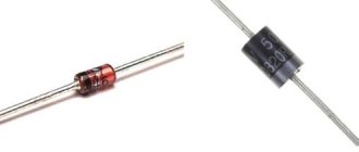
Photo – Thyristor
But, unlike a diode, which is a two-layer (PN) transistor (PNP, NPN), a thyristor consists of four layers (PNPN) and this semiconductor device contains three pn junctions. In this case, diode rectifiers become less efficient. This is well demonstrated by the thyristor control circuit, as well as any electricians’ reference book (for example, in the library you can read a book by the author Zamyatin for free).
A thyristor is a unidirectional AC converter, meaning it conducts current in one direction only, but unlike a diode, the device can be made to operate as an open circuit switch or as a DC rectifying diode. In other words, semiconductor thyristors can only operate in switching mode and cannot be used as amplification devices. The key on the thyristor is not capable of moving to the closed position on its own.
The silicon controlled rectifier is one of several power semiconductor devices, along with triacs, AC diodes, and unijunction transistors, that can switch from one mode to another very quickly. Such a thyristor is called high-speed. Of course, the class of the device plays a big role here.
PART TWO REFERENCE DATA OF THYRISTORS
Section three. Power thyristors 3.1. High-speed thyristors
TB151-50, TB151-63 ' S3 2TB151-50, 2TB161-80, 2TB261 80 67 TB161 80, TB161-100 70 TB2-160, TBZ-200 86 TB171 160, TB171 200 102 2TB171 -160, 2TB171-200 117 TB200 ,T6250 120 TB133-200, TB133-250 130 2TB133-200,2TB133-250 146 2TB143-320, 2TB143-400 149 2TB253-630, 2TB253-80О 152 2TB271-25 0 155 TB320,TB400 170 TB143-320DB143-400 186 2TB233 -400 201 TB153-630, TB153-800 214 TB253-800.TB253-1000 229 2TB153-1000 232
3.2. Symmetrical thyristors
TS2-10, TS2-16, TS2-25 245 -S112-10LS112-16 255 2TS112-10, 2TS122-25 258 TS 122-20, TS 122-25 TS2-40, TS2-50, TS2-63, TS2- VO 2G3 TS 132-40, TS132-50 274 2TS132-50, 2TS142-80 276 TS 142-63, TS 142-80 279 TS80.TS125, TS 160 282 TS161-YuO, TS161 125, TS161 160 2 94 2TS161-160. 2TS161-200 301 TS 171 -200, TS171-250 304 2TS171-250, 2TS171-320 310
4.12. Avalanche thyristors
TL2-160, TL2-200 313 2TL171-200, 2TL171-250 324 TL4-250 327 TL171-250, TL171-320 336 2TL271-250 343
4.13.Optocoupler thyristors
T02-Yu 350 TO2-10,TO2-40 353 TO125-10 363 TSO-Yu 366 T0125 12.5 368 T0132-25, TO132-40 370 2T0132-25, 2TO132-40 373 TO142-50. T0142-63, TO142-80 375 2T0142-50, 2T0142-63. 2Т0142-80 378
3.5. Combination-switchable thyristors, thyristors-diodes
Т6К171-125.ТБК171-160 380 ТБК143-250, ТБК143-320 384 ТДЧ171 125/50, ТДЧ171 160/63 387 ТДЧ153-320/125, ТДЧ153-400/160 389
3.6. Thyristors, unpackaged
T130-40. T130-50 392 T140-63. T140-80 395 3.7. Frameless photothyristors TF130-40, TF130-50 397 TF140-63, TF140-80 399
Section four. Power modules 4.1. Thyristor modules
MT2-10 401 MT2-16 403 MT2-25 405 MTT-40 407 MTT-63 409 MTT-80 412 MTT100. MTT125 414 MTT160 416
4.2. Thyristor-diode modules
MTD40 419 MTD63 421 MTD80 423 MTDYu0. MTD125 425 MTD160 428
4.3. Diode-thyristor modules
MDT2-10 430 MDT2-16 432 MDT2-25 434 MDT40 436 MDT63 438 MDT80 440 MDT100 443 MDT125 445 MDT160 447
4.4. Optothyristor modules
MTO2-10 449 MT02 16 . 4^1 MT02-25 4$4 MTOTO40 456 MTOT063 458 MTOTO80 460 MTOTOYUO, MTOT0125 463 MTOTO160 465
4.14.Diode-optothyristor modules
MDTO2-10 468 MDT02-16 470 MDT02-25 472 MDTO40 475 MDT063 477 MDTO80 479 MDTO100, MDTO125, MDTO160 481
4.15.Optothyristor-diode modules
MTOD40 484 MTOD63 486 MTOD80 488
Section five. Coolers for air cooling systems for power thyristors
ОШ 491 0221 492 0131 493 0231 494 0141 495 0151 496 0241 497 Foreign analogues of domestic thyristors 499 Index of thyristor types 503 List of diode types included in 1 2 volts. edition 505
| ANALOGS OF DOMESTIC AND FOREIGN DIODES AND THYRISTORS |
| 08.05.2009 | |
| Title: Analogs of domestic and foreign diodes and thyristors Author: V.P. Cherepanov, A.K. Khrulev. Publisher: M.: KubK-a Year: 1997 Pages: 224 Format: DJVU Size: 1.7 Mb ISBN: 5-85554-156-8 Quality: normal Language: Russian The reference book is built in the form of a table, which shows the standard ratings of domestic diodes and thyristors in accordance with the current rubricator for semiconductor devices and their foreign analogues, indicating various manufacturing companies in the USA, Japan and Western Europe. For ease of use, the book is divided into two parts. The first part shows foreign analogues of domestic diodes and thyristors, which are arranged in alphanumeric sequence. The second part presents domestic analogues of foreign diodes and thyristors, which, in turn, are also arranged in alphanumeric sequence. The publication is intended for specialists involved in the development, operation and repair of radio-electronic equipment, as well as for a wide range of radio amateurs. CONTENTS : Foreign analogues of domestic rectifier, pulse, tunnel, HF and microwave diodes, zener diodes, voltage limiters………. 3 Domestic analogues of foreign rectifier, pulse, tunnel, RF and microwave diodes, zener diodes, voltage limiters………. 71 Foreign analogues of domestic thyristors……………………….. 177 Domestic analogues of foreign thyristors……………………….. 191 Download Analogues of domestic and foreign diodes and thyristors |
https://youtu.be/VTKwljrQvmw
Application of thyristor
The purpose of thyristors can be very different, for example, a homemade welding inverter using thyristors, a charger for a car (thyristor in the power supply) and even a generator are very popular. Due to the fact that the device itself can pass both low-frequency and high-frequency loads, it can also be used for a transformer for welding machines (their bridge uses exactly these parts). To control the operation of the part in this case, a voltage regulator on the thyristor is needed.
Photo - using Thyristor instead of LATR
Don't forget about the ignition thyristor for motorcycles.
Directories on thyristors and analogs, Replacing thyristors, replacing diodes
Thyristors and their foreign analogues. Directory. Cherepanov V.P., Khrulev A.K. 2002
The second volume of the reference publication provides data on electrical parameters, overall dimensions, maximum operational characteristics, information on the main functional purpose of domestic power thyristors. Dynamic pulse frequency temperature dependences of parameters are given and also describes the features of the use of thyristors in radio-electronic equipment
For engineering and technical workers involved in the development, operation and repair of electronic equipment
Year of release: 2002 Author: Cherepanov V.P., Khrulev A.K. Genre: Directory Publisher: M IP RadioSoft Format: DjVu Size: 4.8 MB Quality: Scanned pages Number of pages: 512
Download the book >>>
Book reading program:
CONTENTS Preface 10
Description of design and principle of operation
The thyristor consists of three parts: “Anode”, “Cathode” and “Input”, consisting of three pn junctions that can switch between “ON” and “OFF” positions at very high speed. But at the same time, it can also be switched from the “ON” position for different durations, i.e., over several half-cycles, in order to deliver a certain amount of energy to the load. The operation of a thyristor can be better explained by assuming that it will consist of two transistors connected to each other, like a pair of complementary regenerative switches.
The simplest microcircuits demonstrate two transistors, which are combined in such a way that the collector current, after the “Start” command, flows into the NPN transistor TR 2 channels directly into the PNP transistor TR 1. At this time, the current from TR 1 flows into the channels into the bases of TR 2. These two interconnected transistors are arranged such that the base-emitter receives current from the collector-emitter of the other transistor. This requires parallel placement.
Photo - Thyristor KU221IM
Despite all safety measures, the thyristor may involuntarily move from one position to another. This occurs due to a sharp jump in current, temperature changes and other various factors. Therefore, before you buy a thyristor KU202N, T122 25, T 160, T 10 10, you need to not only check it with a tester (ring), but also familiarize yourself with the operating parameters.
Typical thyristor current-voltage characteristics
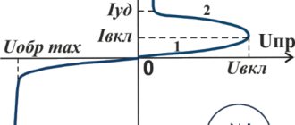
To start discussing this complex topic, look at the diagram of the current-voltage characteristics of a thyristor:
Photo - characteristics of the thyristor current-voltage characteristic
- The segment between 0 and (Vо,IL) fully corresponds to direct locking of the device;
- In the Vvo section, the thyristor is in the “ON” position;
- The segment between the zones (Vvo, IL) and (Vн,In) is the transition position in the on state of the thyristor. It is in this area that the so-called dinistor effect occurs;
- In turn, points (Vн,In) show on the graph the direct opening of the device;
- Points 0 and Vbr are the section where the thyristor is turned off;
- This is followed by the segment Vbr - it indicates the reverse breakdown mode.
Naturally, modern high-frequency radio components in a circuit can affect the current-voltage characteristics in an insignificant way (coolers, resistors, relays). Also, symmetrical photothyristors, SMD zener diodes, optothyristors, triode, optocouplers, optoelectronic and other modules may have different current-voltage characteristics.
Photo - current-voltage characteristic of a thyristor
In addition, we draw your attention to the fact that in this case, device protection is carried out at the load input.
Thyristor. Description, principle of operation, properties and characteristics.
Popular domestic and foreign thyristors. Reference data. The simplest circuits of thyristor regulators.Thyristor is a rather archaic semiconductor device, previously widely used as a power switch for controlling powerful loads. And although at present this element is losing its position to triacs (in AC circuits) and power transistor switches (in DC circuits), the curve of cumulative amateur radio interest in devices made on thyristors is still at a fairly high level. Let's join the process of obtaining knowledge regarding the characteristics, principles of operation, as well as methods of controlling thyristors, and we.
So. A thyristor is a three-terminal semiconductor device, with three (sometimes four) pn junctions and having two stable states: - low conductivity state (closed state); — high conductivity state (open state) .
Fig.1
Figure 1 shows the device of a thyristor and a two-transistor equivalent model, which makes it possible to explain the operation of the device in direct locking mode. For the heap, let’s add the current-voltage characteristic of the thyristor and a circuit that implements the simplest way to control thyristors—supplying a direct current to the control electrode of the device with the amount necessary to turn it on (Fig. 2).
Fig.2
1. First, let's consider the case when the control electrode of the thyristor is turned off (S1 in the diagram is open, Iу on the current-voltage characteristic is 0). There is no current through the load (section III on the current-voltage characteristic), the thyristor is closed, and in order to open it, it is necessary to raise the voltage at the anode of the thyristor so much that an avalanche breakdown of the pn junctions of the semiconductor occurs. Let's make a reservation - we will not be able to record this process, because the value of this voltage is several hundred volts and, as a rule, exceeds the amplitude value of the network voltage. However, when this voltage level is reached (point II on the current-voltage characteristic), the thyristor is unlocked, the voltage drop between the anode and the cathode drops to several volts, the load is connected to the network - the operating mode of the open thyristor begins (section I on the current-voltage characteristic). To close the thyristor, you need to reduce the current flowing through the load (or the voltage at the anode) below the holding current. Moreover, this anode voltage should be many times lower than the unlocking voltage.
2. In order to reduce the thyristor turn-on voltage, S1 should be closed and, thereby, a current specified by the value of the variable resistor R1 should be supplied to the control electrode. The greater the current Iу, the lower the anode voltage the thyristor switches to a conducting state. And at a certain value of the control electrode current, called the rectification current (not shown on the current-voltage characteristic), there will no longer be a hump on the characteristic, and the current-voltage characteristic of the thyristor will become similar to the current-voltage characteristic of a diode. Absolutely the same as in the previous case, in order to close the thyristor it is necessary to reduce the current flowing through the load (or the voltage at the anode) below the holding current value.
The reverse part of the current-voltage characteristic (section IV) corresponds to the reverse blocking mode of the semiconductor and is usually not used. The thyristor remains closed until thermal breakdown occurs.
So, we've decided. To open the thyristor, apply a direct current to the control electrode of the device with the amount necessary to turn it on; to close it, reduce the current flowing through the load (or voltage at the anode) below the holding current value . Those. in our case, presented in Fig. 2, the thyristor will open when S1 is closed at each moment the anode voltage exceeds a certain value depending on the rating of R1, and will close with each half-cycle of the rectified mains voltage at the moment its level approaches zero.
The described method of controlling a thyristor by supplying a direct current to the control electrode is simple, but has a significant drawback - it requires a fairly large current (and, accordingly, power) of the control signal (according to the passport - 200 mA for KU202). The actual values of the control electrode current, sufficient to turn on the thyristor at room temperatures, are usually several times less than the figures given in the passport characteristics (20-40 mA for KU202). However, in most cases, to control thyristors, a pulse method is used, or a method in which an open thyristor shunts the control circuit, preventing unnecessary power dissipation on its elements.
Let's look at a similar method using examples. Figure 3 shows the simplest classical thyristor circuit of a power regulator.
Fig.3
Diode bridge Br1 converts bipolar mains voltage into unipolar double frequency, which allows you to regulate the load voltage during both half-cycles of the mains voltage. Part of the anode voltage of the thyristor, supplied through resistors R1 and R2 to the control electrode of the semiconductor, is used here as the control voltage. Resistor R2 changes the opening moment of thyristor VS1 and, consequently, the average voltage across the load. The lower the value of R2, the greater the current supplied to the control electrode, the sooner the thyristor will open. When R2=0 - the power in the load is maximum (top diagram). When you turn the handle of potentiometer R2, its resistance increases, the current on the control electrode decreases, so the thyristor will not open at the beginning of the half-wave, but after some time, when the current reaches the required level. In addition, as the resistance R2 increases, the control signal receives an additional delay due to the action of the phase-shifting RC circuit formed by R1, R2 and C1, which, in turn, makes it possible to further expand the power control range.
If the load is such that it needs to be supplied with bipolar alternating voltage, the circuit can be converted without any increase in complexity.
Fig.4
Everything is the same, only on the other side.
As we have already mentioned, the devices in question are the simplest and are not without certain disadvantages. Their main disadvantages are poor noise immunity, a strong dependence of the load voltage on temperature, and the need for individual selection of resistors for each thyristor instance. In addition, due to the low input resistance of the thyristor at the control input, the operation of the phase-shifting RC circuit turns out to be very ineffective, which, in turn, causes an insufficiently wide power control range. Schemes in which the formation of control pulses occurs through separate circuits made on transistors, digital or specialized microcircuits work much better. However, since everything has its pros and cons, you have to pay for improvements by complicating the design and the need to use a separate power source.
Since in DC circuits thyristors long ago and without regret gave way to powerful transistors specially designed to operate in key modes, there is no reason to consider them in this context. But the main characteristics of domestic and foreign thyristors will not be at all out of place in the knowledge bank of an inquisitive amateur radio mind. Thyristors whose maximum forward voltage does not reach the amplitude value of the network voltage (300V) will also not be accepted for consideration.
And on the next page we will look at the operating principle, properties and characteristics of symmetrical triode thyristors - triacs.
| U arr. max, V | Ipr max, A | Updrop open, V | Iу otp, mA | Uу otp, V | |||||||||||||||||||||||||||||||||||||||||||||||||||||||||||||||||||||||||||||||||||||||||||||
| KU108V, Zh | 1000 | 500 | 150 (imp) | — | |||||||||||||||||||||||||||||||||||||||||||||||||||||||||||||||||||||||||||||||||||||||||||||
| KU108M,N,S,T | 800 | 400 | 150 (imp) | — | |||||||||||||||||||||||||||||||||||||||||||||||||||||||||||||||||||||||||||||||||||||||||||||
| KU108F, C | 800 | 300 | 150 (imp) | — | |||||||||||||||||||||||||||||||||||||||||||||||||||||||||||||||||||||||||||||||||||||||||||||
| KU109A, B | 700 | 50 | 1 | ||||||||||||||||||||||||||||||||||||||||||||||||||||||||||||||||||||||||||||||||||||||||||||||
| KU109B | 750 | 50 | 1 | ||||||||||||||||||||||||||||||||||||||||||||||||||||||||||||||||||||||||||||||||||||||||||||||
| KU109G | 600 | 50 | 1 | ||||||||||||||||||||||||||||||||||||||||||||||||||||||||||||||||||||||||||||||||||||||||||||||
| KU110A | 300 | 10 | 0,3 | 0,3…0,6 | |||||||||||||||||||||||||||||||||||||||||||||||||||||||||||||||||||||||||||||||||||||||||||||
| KU111A | 400 | 100 | 0,3 | — | |||||||||||||||||||||||||||||||||||||||||||||||||||||||||||||||||||||||||||||||||||||||||||||
| KU113V | 300 | 100 | 0,3 | — | |||||||||||||||||||||||||||||||||||||||||||||||||||||||||||||||||||||||||||||||||||||||||||||
| KU201K, L | 300 | 300 | 2 | ||||||||||||||||||||||||||||||||||||||||||||||||||||||||||||||||||||||||||||||||||||||||||||||
| KU202K | 300 | — | 10 | ||||||||||||||||||||||||||||||||||||||||||||||||||||||||||||||||||||||||||||||||||||||||||||||
| KU202L | 300 | 300 | 10 | ||||||||||||||||||||||||||||||||||||||||||||||||||||||||||||||||||||||||||||||||||||||||||||||
| KU202M | 400 | — | 10 | ||||||||||||||||||||||||||||||||||||||||||||||||||||||||||||||||||||||||||||||||||||||||||||||
| KU202N | 400 | 400 | 10 | ||||||||||||||||||||||||||||||||||||||||||||||||||||||||||||||||||||||||||||||||||||||||||||||
| KU208G | 400 | 400 | 5 | ||||||||||||||||||||||||||||||||||||||||||||||||||||||||||||||||||||||||||||||||||||||||||||||
| KU210A | 600 | 600 | 20 | — | |||||||||||||||||||||||||||||||||||||||||||||||||||||||||||||||||||||||||||||||||||||||||||||
| KU210B | 500 | 500 | 20 | — | |||||||||||||||||||||||||||||||||||||||||||||||||||||||||||||||||||||||||||||||||||||||||||||
| KU210V | 400 | 400 | 20 | — | |||||||||||||||||||||||||||||||||||||||||||||||||||||||||||||||||||||||||||||||||||||||||||||
| KU211A, B | 800 | 800 | 10 | KU211V, G | 700 | 700 | 10 | KU211D, E | 600 | 600 | 10 | KU211ZH, I | 500 | 500 | 10 | KU215A | 1000 | 1000 | 5 | — | KU215B | 800 | 800 | 5 | — | KU215V | 600 | 600 | 5 | — | KU218A | 2000 | 2000 | 20 | — | KU218B | 1000 | 2000 | 20 | — | KU218V | 1800 | 1800 | 20 | — | KU218G | 900 | 1800 | 20 | — | KU218D | 1600 | 1600 | 20 | — | KU218E | 800 | 1600 | 20 | — | KU218ZH | 1400 | 1400 | 20 | — | KU218I | 700 | 1400 | 20 | — | KU219A | 1200 | 1200 | 20 | — | KU219B | 1000 | 1000 | 20 | — | KU219V | 800 | 800 | 20 | — | KU220A-V | 1000 | 1000 | 4 | — | — | KU220G, D | 800 | 800 | 4 | — | — |
| KU221A, B | 700 | 50 | 3,2 | ||||||||||||||||||||||||||||||||||||||||||||||||||||||||||||||||||||||||||||||||||||||||||||||
| KU221B | 750 | 50 | 3,2 | ||||||||||||||||||||||||||||||||||||||||||||||||||||||||||||||||||||||||||||||||||||||||||||||
| KU221G | 600 | 50 | 3,2 | ||||||||||||||||||||||||||||||||||||||||||||||||||||||||||||||||||||||||||||||||||||||||||||||
| KU221D | 500 | 50 | 3,2 | ||||||||||||||||||||||||||||||||||||||||||||||||||||||||||||||||||||||||||||||||||||||||||||||
| KU222A, B | 2000 | — | 400 (imp) | — | |||||||||||||||||||||||||||||||||||||||||||||||||||||||||||||||||||||||||||||||||||||||||||||
| KU222B, G | 1600 | — | 400 (imp) | — | |||||||||||||||||||||||||||||||||||||||||||||||||||||||||||||||||||||||||||||||||||||||||||||
| KU222D, E | 1200 | — | 10 | — | |||||||||||||||||||||||||||||||||||||||||||||||||||||||||||||||||||||||||||||||||||||||||||||
| KU224A | 400 | 50 | 150 (imp) | ||||||||||||||||||||||||||||||||||||||||||||||||||||||||||||||||||||||||||||||||||||||||||||||
| KU228D | 300 | — | 10 | — | — | — | |||||||||||||||||||||||||||||||||||||||||||||||||||||||||||||||||||||||||||||||||||||||||||
| KU228E | 300 | 300 | 10 | — | — | — | |||||||||||||||||||||||||||||||||||||||||||||||||||||||||||||||||||||||||||||||||||||||||||
| KU228ZH | 400 | — | 10 | — | — | — | |||||||||||||||||||||||||||||||||||||||||||||||||||||||||||||||||||||||||||||||||||||||||||
| KU228I | 400 | 400 | 10 | — | — | — | |||||||||||||||||||||||||||||||||||||||||||||||||||||||||||||||||||||||||||||||||||||||||||
| KU239A, B | 400 | — | 250 (imp) | — | |||||||||||||||||||||||||||||||||||||||||||||||||||||||||||||||||||||||||||||||||||||||||||||
| KU240A-V | 400 | — | 100 (imp) | — | 0,5…2,2 |
| Type | U ave. max, V | U arr. max, V | Ipr max, A | Updrop open, V | Iу otp, mA | Uу otp, V |
| 2N687 | 300 | 300 | 25 | |||
| 2N688 | 400 | 400 | 25 | |||
| 2N689 | 500 | 500 | 25 | |||
| 2N690 | 600 | 600 | 25 | |||
| 2N691 | 700 | 700 | 25 | |||
| 2N692 | 800 | 800 | 25 | |||
| 2N5204 | 600 | 600 | 25 | |||
| 2N5205 | 800 | 800 | 25 | |||
| 2N5206 | 1000 | 1000 | 25 | |||
| 2N5207 | 1200 | 1200 | 25 | |||
| 2N6403 | 400 | 400 | 10 | — | ||
| 2N6404 | 600 | 600 | 10 | — | ||
| 2N6405 | 800 | 800 | 10 | — | ||
| 2N6507 | 400 | 400 | 16 | — | ||
| 2N6508 | 600 | 600 | 16 | — | ||
| 2N6509 | 800 | 800 | 16 | — | ||
| BT145-800R | 800 | 800 | 25 | — | — | |
| BT148-400R | 400 | 400 | 4 | — | — | |
| BT148-500R | 500 | 500 | 4 | — | — | |
| BT148-600R | 600 | 600 | 4 | — | — | |
| BT148-600R | 600 | 600 | 4 | — | — | |
| BT149D | 400 | 400 | 0,8 | — | — | |
| BT149G | 600 | 600 | 0,8 | — | — | |
| BT150-500R | 500 | 500 | 4 | — | — | |
| BT150-600R | 600 | 600 | 4 | — | — | |
| BT151-500R | 500 | 500 | 12 | — | — | |
| BT151-650R | 650 | 650 | 12 | — | — | |
| BT151-800R | 800 | 800 | 9 | — | — | |
| BT152-400R | 400 | 400 | 20 | — | — | |
| BT152-600R | 600 | 600 | 20 | — | — | |
| BT152-800R | 800 | 800 | 20 | — | — | |
| BT168E | 500 | 500 | 0,8 | — | — | |
| BT168G | 600 | 600 | 0,8 | — | — | |
| BT169D | 400 | 400 | 0,8 | — | — | |
| BT169G | 600 | 600 | 0,8 | — | — | |
| BT258-500R | 500 | 500 | 8 | — | — | |
| BT258-600R | 600 | 600 | 8 | — | — | |
| BT258-800R | 800 | 800 | 8 | — | — | |
| BT300S-600R | 600 | 600 | 8 | — | — |
Thyristor check
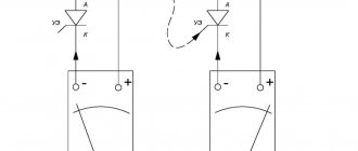
Before you buy a device, you need to know how to test a thyristor with a multimeter. The measuring device can only be connected to a so-called tester. The diagram by which such a device can be assembled is presented below:
Photo - thyristor tester
According to the description, it is necessary to apply a positive voltage to the anode, and a negative voltage to the cathode. It is very important to use a value that matches the resolution of the thyristor. The drawing shows resistors with a nominal voltage of 9 to 12 volts, which means that the tester voltage is slightly higher than the thyristor. After you have assembled the device, you can begin to check the rectifier. You need to press the button that sends pulse signals to turn it on.
Testing the thyristor is very simple; a button briefly sends an opening signal (positive relative to the cathode) to the control electrode. After this, if the running lights on the thyristor come on, the device is considered inoperative, but powerful devices do not always react immediately after the load arrives.
Photo - circuit tester for thyristors
In addition to checking the device, it is also recommended to use special controllers or a control unit for thyristors and triacs OWEN BOOST or other brands; it works approximately the same as a power regulator on a thyristor. The main difference is a wider range of voltages.
Video: operating principle of a thyristor
Specifications
Let's consider the technical parameters of the KU 202e series thyristor. This series presents domestic low-power devices, the main use of which is limited to household appliances: it is used to operate electric furnaces, heaters, etc.
The drawing below shows the pinout and main parts of the thyristor.
Photo - ku 202
- Set reverse on-state voltage (max) 100 V
- Closed voltage 100 V
- Pulse in open position - 30 A
- Repeated pulse in open position 10 A
- Average voltage <=1.5V
- Non-unlocking voltage >=0.2 V
- Set open current <=4 mA
- Reverse current <=4 mA
- Constant type unlocking current <=200 mA
- Set constant voltage <=7 V
- Turn-on time <=10 µs
- Turn-off time <=100 µs
The device turns on within microseconds. If you need to replace the described device, then consult a sales consultant at an electrical store - he will be able to select an analogue according to the diagram.
Photo - thyristor Ku202n
The price of a thyristor depends on its brand and characteristics. We recommend buying domestic devices - they are more durable and affordable. In spontaneous markets you can buy a high-quality, powerful converter for up to a hundred rubles.