The design of a universal commutator electric motor has no fundamental differences from the design of a DC commutator electric motor with field windings, except that the entire magnetic system (both stator and rotor) is laminated and the field winding is sectioned. The laminated design of both the stator and the rotor is due to the fact that when operating on alternating current, they are penetrated by alternating magnetic fluxes, causing significant magnetic losses.
Sectioning the field winding is caused by the need to change the number of turns of the field winding in order to bring the performance characteristics closer when operating the electric motor from direct and alternating current networks [2].
A universal commutator electric motor can be made with both series and parallel and independent excitation.
Currently, universal commutator electric motors are made only with series excitation.
Thus, the resulting electromagnetic torque when the engine is running on AC power pulsates. Pulsations of the electromagnetic torque practically do not disrupt the operation of the engine. This is explained by the fact that with a significant pulsation frequency of the electromagnetic moment (
) and a large moment of inertia of the armature, the rotation of the latter turns out to be uniform.
Types of CD
It is customary to classify these devices according to the type of power supply; depending on this, two groups of CDs are distinguished:
- Direct current. Such machines are characterized by high starting torque, smooth speed control and a relatively simple design.
- Universal. They can operate from both constant and variable power sources. They are distinguished by their compact size, low cost and ease of management.
The first ones are divided into two subtypes; depending on the organization of the inductor, it can be on permanent magnets or special excitation coils. They serve to create the magnetic flux necessary to generate torque. CDs, where excitation coils are used, are distinguished by types of windings, they can be:
- independent;
- parallel;
- consistent;
- mixed.
Having dealt with the types, let's consider each of them.
Universal type CD
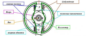
The figure below shows the appearance of an electric machine of this type and its main structural elements. This design is typical for almost all CDs.
Design of a universal commutator motor
Designations:
- A is a mechanical commutator, it is also called a collector, its functions were described above.
- B – brush holders, used to attach brushes (usually made of graphite), through which voltage is supplied to the armature windings.
- C – Stator core (made up of plates, the material for which is electrical steel).
- D – Stator windings, this unit belongs to the excitation system (inductor).
- E – Armature shaft.
For devices of this type, excitation can be serial or parallel, but since the latter option is not currently produced, we will not consider it. As for universal sequential excitation CDs, a typical diagram of such electric machines is presented below.
Scheme of a universal commutator motor
A universal CD can operate on alternating voltage due to the fact that when the polarity changes, the current in the field and armature windings also changes direction. As a result of this, the torque does not change its direction.
Features and scope of universal CDs
The main disadvantages of this device appear when it is connected to AC voltage sources, which is reflected in the following:
- decrease in efficiency;
- increased sparking in the brush-collector unit, and as a result, its rapid wear.
Previously, CDs were widely used in many household electrical appliances (tools, washing machines, vacuum cleaners, etc.). At the moment, manufacturers have practically stopped using this type of motor, giving preference to brushless electric machines.
Now let's look at collector electric machines operating from constant voltage sources.
CD with permanent magnet inductor
Structurally, such electric machines differ from universal ones in that permanent magnets are used instead of excitation coils.
Design of a permanent magnet commutator motor and its diagram
This type of CD is most widespread compared to other electric machines of this type. This is due to the low cost due to the simplicity of the design, simple control of the rotation speed (depending on voltage) and changing its direction (it is enough to change the polarity). The motor power directly depends on the field strength created by the permanent magnets, which introduces certain restrictions.
The main area of application is low-power drives for various equipment, often used in children's toys.
CD on permanent magnets from a toy from the times of the USSR
The advantages include the following qualities:
- high torque even at low speed;
- dynamic management;
- low cost.
Main disadvantages:
- low power;
- magnets lose their properties due to overheating or over time.
To eliminate one of the main disadvantages of these devices (magnet aging), special windings are used in the excitation system; let’s move on to considering such CDs.
Independent and parallel field coils
The first received this name due to the fact that the windings of the inductor and armature are not connected to each other and are powered separately (see A in Fig. 6).
Figure 6. CD circuits with independent (A) and parallel (B) excitation windings
The peculiarity of this connection is that the power supply U and UK must be different, otherwise a moment of force will arise. If it is impossible to organize such conditions, then the armature and inductor coils are connected in parallel (see B in Fig. 6). Both types of CD have the same characteristics; we found it possible to combine them in one section.
The torque of such electric machines is high at low speed and decreases as it increases. It is characteristic that the armature and coil currents are independent, and the total current is the sum of the currents passing through these windings. As a result of this, when the excitation coil current drops to 0, the CD is likely to fail.
The scope of application of such devices is power plants with a power of 3 kW or more.
Positive features:
- the absence of permanent magnets eliminates the problem of their failure over time;
- high torque at low speed;
- simple and dynamic control.
Minuses:
- the cost is higher than that of permanent magnet devices;
- it is inadmissible for the current to drop below the threshold value on the excitation coil, as this will lead to breakdown.
Series field coil
The diagram of such a CD is shown in the figure below.
CD circuit with sequential excitation
Since the windings are connected in series, the current in them will be equal. As a result of this, when the current in the stator winding becomes less than the rated one (this happens with a light load), the power of the magnetic flux decreases. Accordingly, when the load increases, the flux power increases proportionally, until the magnetic system is completely saturated, after which this dependence is broken. That is, a further increase in the current in the armature coil winding does not lead to an increase in the magnetic flux.
The above-mentioned feature is manifested in the fact that a compressor of this type cannot be started at a load one-quarter less than the nominal load. This can lead to the rotor of the electric machine sharply increasing the rotation speed, that is, the engine will go into overdrive. Accordingly, this feature introduces restrictions on the scope of application, for example, in belt drive mechanisms. This is due to the fact that when it breaks, the electric machine begins to operate in idle mode.
Asynchronous motor malfunctions
There are 2 types of single-phase asynchronous motors - bifilar with a starting winding and capacitor. Their difference is that in bifilar single-phase motors the starting winding operates only until the motor accelerates. Afterwards it is turned off by a special device - a centrifugal switch or a start-up relay in refrigerators. This is necessary because after overclocking it reduces efficiency. In capacitor single-phase motors, the capacitor winding runs all the time. Thanks to this, you can change the direction of rotation.
Why does the concrete mixer not start or does it turn on and immediately turn itself off? If, when starting the equipment, the engine hums, but the drum does not. Most often, this happens in three-phase models connected to.
Operating principle
When current flows through the armature winding, a magnetic field is generated, the direction of which can be determined using the gimlet rule. The constant magnetic field of the stator interacts with the field of the armature, and it begins to rotate due to the fact that like poles repel, attracting opposite ones. Which is perfectly illustrated by the picture below.
When the brushes move to other lamellas, the current begins to flow in the opposite direction (if we consider the above example), the magnetic poles change places and the process repeats.
In modern commutator machines, a two-pole design is not used due to uneven rotation; at the moment of switching the direction of the current, the forces acting on the armature will be minimal. And if you turn on the engine, the shaft of which has stopped in this “transition” position, it may not begin to rotate at all. Therefore, on the commutator of a modern DC motor there are significantly more poles and winding sections laid in the grooves of the laminated core, thus achieving optimal smoothness of movement and torque on the shaft.
The principle of operation of a commutator motor is explained in simple language for dummies in the following video, we strongly recommend that you familiarize yourself with it.
Quadcopter motor markings, decoding
In accordance with generally accepted standards, the marking of electric drives of drones is as follows:
- The first letter means the drive class and reflects the quality of workmanship:
- “V” series – this is how electric motors for racing and premium class quadcopters are usually designated, made from the best materials with high precision assembly;
- “X” series – a series of electric motors for mid-price quadcopters of appropriate quality and assembly;
- series “A” – electric motors for budget drones.
- Four numbers indicate the parameters of the magnetic circuit. The first two numbers are the diameter (in millimeters), the next two are the thickness of the set (in millimeters).
- The fraction is also separated by numbers indicating the number of turns.
- The last letter is the winding type.
For example, A2212/15T:
- A – electric motor of a budget quadcopter;
- 22 – magnetic circuit with a diameter of 22 millimeters;
- 12 – set thickness 12 millimeters;
- 15 – 15 turns;
- T – (sometimes the designation Δ may appear) – “triangle” winding.
The marking may also indicate the number of revolutions per minute per unit of voltage (Volt) - KV. We will talk about this indicator in more detail later.
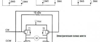
Connection diagram (simplified)
A typical connection diagram provides for the output of up to ten contacts to the contact strip. The current L flowing through one of the brushes enters the commutator and armature, then passes to the stator windings through the second brush and jumper, leaving the neutral N.
This method of connection does not provide for reversing the motor, since connecting the windings in parallel leads to a simultaneous change in the poles of the magnetic fields. As a result, the direction of the moment is always the same.
We recommend:
- Dji phantom 3 standard: instructions, description, advantages
- What is the name of an electric board without a steering wheel?
- Classification of electric motors
It is possible to change the direction of rotation if you change the locations of the winding outputs on the contact strip. The motor is turned on directly when the rotor and stator outputs are connected to a brush-commutator mechanism. To turn on the second speed, the terminals of half the winding are used. We must not forget that from the moment of such connection the motor operates at maximum power, so its operation time cannot exceed 15 seconds.
Video: Connecting and adjusting engine speed from a washing machine
Brushless motor advantages and disadvantages
The brushless motor guarantees a longer life since there is actually no brush to wear it down. They can work more than 1000 hours. Brushless motors are more energy efficient than brushed motors.
However, they are initially more expensive than brushed motors. You also need to connect devices such as encoders and controllers.
A brushed motor makes a lot of noise, while their brushless counterparts are less noisy. The brushless motor also offers a higher torque-to-weight ratio. What else? There is no need to deal with ionizing sparks from the switch and electromagnetic interference.
Motor functionality
The circuit diagram of a commutator motor perfectly demonstrates how this unit converts electricity into mechanical energy and vice versa.
This suggests that such a device can even be used as a generator. When a current passes through a conductor that is located in a magnetic field, certain forces act on it. In this case, the right-hand rule is actively working, having a direct impact on the final engine power. The collector unit operates precisely on this principle. The standard diagram clearly shows that one pair of conductors is placed in a magnetic field, the current of which is directed in different directions in the same way as the forces. The sum they form provides the torque required for the equipment. In the commutator motor, manufacturers have also added a whole complex of additional components that guarantee the identical direction of the current over the poles.
Due to the fact that there are several more coils on the armature, the unevenness of the stroke has been completely eliminated. In addition, craftsmen no longer need to use direct current, since conventional magnets have been replaced by more powerful coils. At the final stage of production, the torque assumed a single direction.
Causes of major engine malfunctions
Three-phase motors are more efficient than single-phase motors per volt. If you have a Volt input in your house or garage, then be sure to buy a compressor or machine with a three-phase electric motor. This will ensure more stable and economical operation of the devices. To start the motor, you will not need various starting devices and windings, because a rotating magnetic field appears in the stator immediately after connecting to the Volt electrical network. It is also possible to connect a three-phase motor to the Volt network using capacitors according to this scheme. But there will be a significant drop in the power and efficiency of its operation.
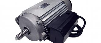
Appearance of a commutator motor
Brush compartment cover
Beginners are concerned about the question of how to identify a commutator motor. As easy as pie. Look at the photo of the grinder, made specifically for the VashTekhnik portal: the sides of the case show caps made of insulating material for a slotted screwdriver. Having taken the trouble to unscrew it, inside we see contact pads and a graphite brush spring. A key feature of a commutator engine. The electric tool is equipped with devices for quick replacement of graphite, which is considered a consumable material.
Graphite brush contact pad and spring
Commutator motor brushes
A spare kit is included in the box. The close-up photo shows the replacement brushes. Each includes:
- Graphite electrode. The shape varies widely depending on the type of engine. Graphite is sharpened with needle files, files, obtaining the specified dimensions. Not critical. The main thing is to avoid large gaps; the shape of the holder is specially designed to reduce backlash. The graphite electrode wears off, sparking increases until a circular fire appears. The commutator motor gets very hot and smokes. The process can be seen by a persistent YouTube viewer (see English domain).
- The contact brass pad is used to connect power. In household instruments, it is often 230 volts with one caveat: part of the period of the sine wave is cut off. Allows you to adjust the speed (forget grinders). The larger the cut-off angle, the lower the shaft speed. The control circuit is formed by a thyristor and adjusted by a variable resistor.
- The spring is stretched between the contact pad and the graphite electrode. Serves the purpose of pressing. As a result, the graphite electrode slides around the collector, simultaneously lubricating the surface. The resistance of the brushes shown in the figure is close to 7 Ohms, comparable to the windings. On alternating current the situation changes. The inductive resistance of the windings increases sharply, but the brushes remain the same. Graphite plays the role of limiting resistors; thanks to carbon, the rotor current is powerless to rise above 15 A.
- The key part of the brushes is a highly flexible cable made of copper threads. It bends well, and as the graphite brush grinds down during use, it easily stretches, reaching the desired size.
Types of commutator motors
For ease of perception in any area, there is a classification of products according to criteria, features, and functionality. As for collector installations, classification takes place according to different parameters.
Scheme of a universal commutator motor.
When classified by nutrition:
- Universal commutator motor;
- Collector unit (direction of movement of charged particles in an electric field = const);
- With permanent magnet inductor;
- With inductor on excitation coils:
- Excitation coil (independent winding type);
- Excitation coil (parallel winding type);
- Excitation coil (series winding type);
- Excitation coil (mixed winding type).
Universal collector unit.
The units are used in everyday life; a 220V AC commutator motor is used in household appliances. The motor consumes direct and alternating current. Popularity in use is due to reverse, rotation speed adjustment, and the need for a frequency above 3000 rpm.
Using a single-phase AC commutator motor, the stator and rotor windings are connected in series or parallel. No one makes the last connection option anymore. The universal single-phase collector unit works with alternating and direct current.
Disadvantages of the universal mechanism:
- Unit cost;
- Difficulty of maintenance;
- Noisy operation, complex controls, radio interference;
- The useful action is lower than necessary if an alternating current source is used;
- Wear of brushes due to the formation of sparks.
Collector unit (current = const).
Permanent magnet inductor.
The design difference from the universal installation is the use of magnets rather than field coils. The unit is popular and more widespread than other types of collector installations. The positive point is the cost and simplicity of the design. In addition, the device is easy to operate. The stumbling block is the magnets used, which are directly related to the power characteristics of the installation. The installation is affected by the field generated by the magnets.
| Positive aspects | Negative aspects |
| Significant torque at low speed; Wide range of adjustments; The price of the unit is affordable for consumers. | Low power; Aging of magnets, loss of properties. |
Commutator motor with permanent magnet inductor.
Excitation coils (independent and parallel)
The name of the type was obtained as a result of independent power supply. The peculiarity is that for torque to occur, the power supply of the inductor and the armature must be different, otherwise the rotor of the installation will not spin.
If it is not possible to organize the supply of different currents, then the connection is made in parallel. Both types are the same in terms of characteristics. The torque of power plants is high (even at low rotation), and as the frequency increases, the torque decreases. Feature: independence of the coil and armature. For the unit to fail, it is enough for the current exciting the coil to drop to the value “0”.
Independent excitation circuit:
| Positive aspects | Negative aspects |
| There are no magnets, so time does not affect the performance of the unit; Low speed - high torque; Easy adjustment, organized by the regulator. | The price is too high in comparison with opponents; A drop in the excitation coil current below the limit value is fraught with breakdown. |
Parallel excitation circuit:
Excitation winding (series type)
Sequence assumes equal current value. When the stator current is below the calculated value, the power of the magnetic flux decreases. The increase in load is comparable to the increase in flux power, until the limiting level is reached, when the increase in current does not increase the magnetic flux.
This feature does not allow the engine to start if the calculated load is below 25%. Having done this, there will be a sharp uncontrolled increase in rotation speed. This feature has left its mark on the use of the units; however, if the installation power is below 200W, the load may drop, even to idle speed.
| Positive aspects | Negative aspects |
| There are no magnets, so time does not affect the performance of the unit; The torque value is high, while the speed is insignificant. | The cost is too high, opponents are cheaper; The torque value decreases with increasing speed; Difficulties in adjusting the rotation speed of the unit; Operation without load leads to breakdown of the unit. |
Series excitation circuit.
Best Brushless Motors for Quadcopters
Here is a list of the most popular brushless quadcopter motors.
Attention! Before purchasing, be sure carefully check all the technical characteristics and parameters of the motor: dimensions, shaft length, diameter, direction of rotation, power characteristics, voltage, ESC parameters, etc.
| Brushless motor | Photo | KV | Price on aliexpress |
| Emax ECO II Series 2207 | 1700-2400 | from 1200 rub | |
| Readytosky 2205-2300 CW/CCW | 2300 | from 500 rub | |
| Sparkhobby RS2205 PRO | 2300 | from 300 rub. | |
| Emax ECO II 2306 | 1700-1900-2400 | from 4000 rub | |
| DYS Samguk Wei 2207 series | 1750-2300-2600 | from 560 RUR | |
| T-motor F40 PRO IV (professional) | 1950-2400 | from 8000 | |
| Sunnysky X2212 | from 980 to 2450 | from 1300 | |
| Surpass Hobby C4260 | 500-600 | from 2700 rub. |
