Home > Generators > Blocking generator: operating principle
Devices of this type are used to create signals with high duty cycle that are rarely repeated. They use a transformer, which is included in the feedback circuit. The presence of galvanic isolation at the output allows the formation of high-voltage pulses. This feature is used to power line scanning units and Tesla coils.
What does a blocking generator look like?
A simple generator blocking circuit can be assembled without difficulty at home.
Principle of operation
The diagram shown below will help you understand the functioning of the blocking generator.
Schematic diagram of a typical generator
The following list shows the main stages of work:
- After applying voltage through resistor R1, capacitor C is charged. The completion time of this process is determined by the parameters of these elements.
The amount of current is limited by the resistance of the circuit, and the voltage at the capacitor terminals does not have time to reach its maximum.
- As soon as it reaches a certain value, the transistor will begin to open. The current begins to flow through the circuit: transformer winding – collector – emitter. At this stage, the voltage reaches its maximum almost instantly and the current increases relatively slowly.
- It induces an EMF in the transformer winding connected to the base, which further increases the voltage and opens the transistor. This process ends when the transformer core is saturated (the material is not capable of conducting a magnetic field of a certain intensity). It will also stop when the base current increases, until the saturation threshold of the semiconductor device.
- The transistor turns off. Charging of capacitor C begins. The inductance of the transformer winding produces an emf in the direction opposite to the original one. This speeds up the closing of the transistor.
The principle of operation of a blocking generator is easier to understand with the help of timing diagrams, which illustrate the change in electrical parameters in individual parts of the circuit.
Current and voltage diagrams
These drawings must be studied in conjunction with the following drawing, which shows another circuit diagram of a blocking generator.
Generator blocking circuit
The figure above does not show a specific load (designation Rн). The diode performs damping functions. It prevents voltage surges that could damage the transistor.
The stages described above are clearly visible in the diagrams. Below are the features that are characteristic of the second scheme:
- The combination t0 marks the moment when the voltage at the base of the transistor is not enough to open it.
- The time interval t0 – t1 indicates the period of gradual opening of the transistor. At the end point, saturation has occurred, so changing the base current does not affect the pulse shape.
- However, the capacitor discharge occurs. Therefore, there is a gradual decrease in the base current.
- Since the load on the collector has inductive characteristics, the current Ic does not decrease. The duration of this period is determined by the parameters of the transformer core.
- The pulse cutoff begins at point t2. The current created by induction decreases, which provokes a gradual closing of the transistor switch. The figures show when current appears in the opposite direction. This process intensifies the discharge of the capacitor. The closing speed of the transistor increases, and the cutoff becomes steep (formed in a short time).
- Point t3 indicates the moment the transistor gate is completely closed. After it, the appearance of oscillatory processes is permissible. To block them, a diode is installed in this circuit.
TV Service
IP repair. Division into a blocking generator and a control circuit. The power supply based on discrete elements (transistors) is designed schematically in two parts: 1) a self-oscillator (blocking generator), 2) a device for controlling the operation of the self-generator (control circuit, KU switch and R limit). M50.jpg The autogenerator ensures the generation of pulse voltages at the TPI, and the device controls the output voltages of the power source and regulates the operation of the autogenerator when they change. The self-oscillator is usually made on: a) a powerful output transistor, b) a TPI winding operating in POS (Positive Feedback) mode, c) resistance Rst and capacitance Csv, connected in series between the POS winding and the base of the transistor d) bias resistance Rcm, switched on between Upit+ (rectified mains voltage) and the base of the transistor. e) a diode that ensures a constant unlocking current at the base of the transistor and shunts the RC circuit in the forward direction. The POS winding, Rst and Cst form a pulse of a certain shape based on the transistor. The diode forms a positive bias at the base of the transistor, thereby providing the necessary swing on the TPI windings. Rcm is used for the initial start of the autogenerator.
The idea of a repair technique. Disconnect the blocking generator from the control circuit and some of the loads on the secondary windings of the power supply, check its functionality, if necessary, repair it, and then connect the control circuit, loads, etc. in several stages. at the same time check the functionality and, if necessary, repair. But if you simply turn on the autogenerator, the power supply will immediately go into overdrive and the key transistor will fail. Also, if there are defects in the generator itself, the key transistor may also fail. Therefore, you need to check in two modes. All loads in the secondary power supply are switched off, with the exception of the diode and capacitance at B+, and a lamp of usually 220 volts 60 watts is connected in parallel to this capacitance. Then the control circuit and its power supply are turned off and a 220 volt 100 watt lamp is connected to the gap between the mains capacitor and the TPI winding. M50_2-2.jpg IP is turned on. Both lamps should light up and the IP should not make any extraneous sounds. If the lamp on B+ does not light up or the IP crackles, squeals, etc., then the blocking generator needs to be repaired. If normal, then the capacitor-TPI connection is restored and a 100-watt lamp is soldered in instead of the fuse. It is advisable to select lamps in such a way that the voltage at B+ is as close to optimal as possible. For the network, a set of lamps 200 watt, 150 watt, 100 watt, for the load 100 watt, 60 watt, 40 watt. If you don’t know which llamas are optimal for a given power supply, then it’s better to start with a 100-watt network and a 100-watt load. An increase in the power of the llama in the network circuit increases B+, an increase in power in the load decreases. After checking the functionality of the blocking generator in the second mode, the control circuit, loads, etc. are connected in series. At the same time, the functionality is checked and, if necessary, repaired.
For example, the repair method for IP chassis M50.
M50_PS.jpg Voltage at the working power supply: B+112 volts Q801 K 5.1v, E 9.7v, B 9.2v, Q802 K 0.0v, E 2.0v, B?, Q803 K 1.6v, E 0, 2c, B 0.4c.
The repair begins with checking the functionality of the generator. The following parts are unsoldered from one end: R831, R832, R831A, L804 (secondary IP) D805, D807, C810 (autogenerator control device). A 60-watt lamp is soldered parallel to C827 (B+) and between C806 and the 3rd leg of a 100-watt TPI.
M50_PS_2-2.jpg We connect the IP to the network. The IP must operate without any extraneous sounds (screaming, whistling, etc.). At B+ 64 volts. If there is no startup or extraneous sounds are produced by the TPI, then the blocking generator needs to be repaired. If normal, then the junction between the mains capacitor and TPI is restored and a 100-watt lamp is soldered in instead of the fuse. The operation of the blocking generator in this mode is checked. There should be 112 volts at B+ on the 82 volt mains capacitor. D805 and D807 are soldered back in. The following voltages should be Q801 K 10.0v, E 10.0v, B 9.4v, Q802, K 0.6v, E 3.1v, B 2.8v, Q803 K 3.3v, E 0.6v, B 0 ,6c. If there are large voltage deviations, we repair the control device. If normal, then solder back the C810, unsolder the lamp between the mains capacitor and the TPI and restore the connection at this point. After switching on, the voltage on B+ should be +112 volts. If necessary, adjust VR801. Then the lamp with B+ is unsoldered and R831, R832, R831A, L804 are soldered back. And the operation of the TV is checked and, if necessary, other units are repaired.
Thank you for your help in preparing the material viktor_ramb and Admin.
Calculation
Operating principle of a synchronous generator
The principle of operation of the blocking generator is clear. Below is a calculation that will help you choose the right transistor of the second circuit diagram.
For the example, the following initial parameters were used:
- frequency (F) – 40 kHz;
- duty cycle (C) – 0.25;
- amplitude (AM) – 6 V;
- resistance Rng (load) – 30 Ohm;
- voltage at the output of the power source (PS) – 300 V.
The permissible base-collector voltage should be from 1.5 to 2 times greater than NP. For this example - from 450 to 600 V.
The collector current ( Ik ) is determined by the formula:
Ik must be equal to or greater than ((3...5)*AM*CTF)/ Rng.
KTF is a coefficient that takes into account the features of energy transformation (collector - load windings):
CTF=(1.2*AM) / NP=(1.2*6)/300=0.024.
Thus, the permissible collector current must be greater than the following values:
((3…5)*6*0,024)/ 30 = 0,0144…0,024.
The maximum frequency (Chmax, kHz) is calculated using the following formula:
Hmax≥(5…8) * H = (5…8) * 40 = 200…320.
Based on the data obtained, the type of transistor is determined.
Parameters of a suitable conditional device:
- maximum collector-base voltage (NCV) – 620 V;
- maximum base-emitter voltage (NBE) – 8 V$
- maximum collector current (Ik) – 0.03 A;
- collector-base current (Ikb) – 12 µA;
- maximum frequency (Chmax) – 1000 kHz;
- base resistance (Rb) – 250 Ohm.
Calculation and practice allow you to assemble a blocking generator with your own hands
To create a blocking generator correctly, you need to know theory and practice, and be able to make calculations.
Video
Electric heating - heating devices
Coffee capsules Nescafe Dolce Gusto Cappuccino, 8 servings (16 capsules)
435 ₽ More details
Coffee capsule Nescafe Dolce Gusto Cafe O Le Coffee with milk, 3 packs of 16 capsules each
1305 ₽ More details
Samsung Galaxy S10 smartphones
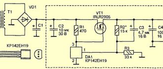
Field-effect transistor generator
The operating principle of this device does not differ from the options discussed above. But changes have been made to the scheme that significantly increase energy efficiency, reliability and durability.
Field-effect transistor generator blocking circuit
Recommendations for proper assembly of the product:
- The domestic transistors and diodes indicated in the drawing can be replaced with similar imported semiconductor devices with suitable electrical characteristics.
- Resistance R2 is selected so that the voltage at C1 in idle mode does not exceed 450 V. This setting will prevent breakdown of the semiconductor junction of the VT transistor
- To avoid damaging the device, it should not be turned on without load.
- Resistance R6 performs protective functions. Its presence allows you to disconnect the generator from the network when the circuit breaker S is open
Blocking generator is the simplest transformer. for charging gauss capacitors
- 2 Pages
- 1
- You cannot create a new topic
- You can't reply to the topic
#1 Fan_TOM_AS
- Group: Users
- Posts: 817
- Registration: 08 August 10
Many people who decide to assemble a Gauss stop at the issue of a converter; there are tons of circuits on the Internet, but this one is as simple as two fingers, uncritical of details, cannot fail; almost all the parts live in the old TV
Actually the scheme itself is nothing complicated. you will need such details as: my core is TOR (in TV there are U-shaped fuel assemblies, they are also suitable) there is also PM. R.M. ETD. Sh. U. and TeDe and TePe
Next you need a transistor (you can also find them on TVs)
I used the imported NPN 13007 and the Soviet PNP kt837. The circuit works with both transistors, you just need to change the power polarity and deploy the electrolyte. varnished wire for winding the transformer, thicker and thinner (I have 1mm and 0.56mm)
▍ Solution for the laziest
The simplest solution was to use a school tube sound generator (please note that only a tube sound generator will do, because it produces a high voltage). The thing is also very scarce, but it is still possible to find it for reasonable money. Provides up to 350 V effective voltage, has a high internal resistance and is ideal for selecting IEL power parameters. Compare the brightness of the glow at 400 and 1200 Hz.
The indicator glows at a frequency of 400 Hz.
The indicator glows at a frequency of 1200 Hz.
The idea to use a tube generator for these purposes also belongs to radiolok, for which many thanks to him!
▍ Is meander suitable for ELI?
Is it possible to power ELI from rectangular alternating voltage? The book "Electroluminescent Alphanumeric Indicators" mentioned above gives the following answer:
Excitation of electroluminophores by rectangular pulses results in two flashes of phosphor brightness occurring in one voltage pulse. One of them corresponds to the front, and the second to the decline of the exciting pulse (Fig. 3). The flat part of the voltage pulse corresponds to the attenuation of the first, and the pause between pulses - the second brightness peak.
At a frequency of 400 Hz, the pulse repetition rate will be 800 Hz, the human eye will see a smooth glow.
But in fact, you can also create a sinusoidal voltage by generating it using PWM; I even found a good article on the topic. But I couldn’t do it rudely, if readers find the topic interesting and ask in the comments, then I will get the Arduino to produce a 220 V sinusoidal signal. It just takes a little more time.
The most famous ways to generate free power
The most popular are the works of Nikola Tesla. He was one of the first scientists to work on free energy generator circuits. He was involved in the development of wireless communications. It was based on flat coils with a magnetic field inside. As a result, the transformer has asymmetric mutual inductance. If you connect a load to the output circuit, this will not affect the power consumed by the primary winding.
During his work, Tesla began to pay attention to the transformer operating at resonance. Converted power into efficiency, which should have been more than one
To create such a circuit, I used single-wire designs. It was Tesla who created the term “free vibrations” and in his studies pointed to sinusoidal oscillations in an electrical circuit. Tesla's works are still famous today. Free energy has many followers.
How to get energy from the ether with your own hands?
Microquantum etheric flows in many such generators are the main sources from which energy for the generators comes. You can try connecting systems through capacitors and lithium batteries. You can choose different materials depending on the performance they provide. Then the number of kW will be different.
So far, free energy is a phenomenon little studied in practice. Therefore, many gaps remain in the design of generators. Only practical experiments help to find the answer to most questions. But many large manufacturers of electronic devices are already interested in this direction.
How to make a small free energy generator with your own hands
The scheme used is as follows:
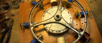
- take the cooler (fan) from the computer;
- remove 4 transformer coils from it;
- replace with small neodymium magnets;
- orient them in the original directions of the coils;
- By changing the position of the magnets, you can control the rotation speed of the motor, which operates completely without electricity.
Such an almost perpetual motion machine remains operational until one of the magnets is removed from the circuit. By connecting a light bulb to the device, you can illuminate the room for free. If you take a more powerful motor and magnets, the system can power not only a light bulb, but also other household electrical appliances.
All from nothing
Research on the types of “green energy” has recently been carried out more and more intensively, as this is the way to the future. Our planet initially has everything for human life. You just need to be able to take it and use it for good. Do many scientists and amateurs create such devices? as a generator of free energy. With their own hands, following the laws of physics and their own logic, they do something that will benefit all of humanity.
So what phenomena are we talking about? Here are a few of them:
- static or radiant natural electricity;
- use of permanent and neodymium magnets;
- obtaining heat from mechanical heaters;
- transformation of earth energy and cosmic radiation;
- implosion vortex engines;
- solar thermal pumps.
Each of these technologies uses a minimal initial pulse to release more energy.
How to make a free energy generator with your own hands? To do this, you need to have a strong desire to change your life, a lot of patience, diligence, a little knowledge and, of course, the necessary tools and components.