Electromagnetic relays are often used to control powerful loads in AC circuits. The contact groups of these devices serve as an additional source of unreliability due to their tendency to burn and weld. Another disadvantage is the possibility of sparking during switching, which in some cases requires additional safety measures. Therefore, electronic keys are preferable. One of the variants of such a key is made using triacs.
“Universal” electromagnetic relay
An electromagnetic relay is essentially a controlled mechanical switch: when you apply current to it, it closes the contacts, when you remove the current, it opens. The contacts are just that: contacts: metal “nickels” that press against each other. That is why such a relay can control both DC and AC loads.
The relay coil itself is a strong inductive load, which leads to additional problems (read below), so to control the “bare” relay we need an additional power and protective circuit.
After studying this lesson, you will be able to compose it yourself (transistor and diode), and now we will talk about relay modules: a ready-made board on which the relay itself stands, as well as switching circuits, protection circuits and even optical isolation. Such modules are “family” - with several relays on board. Thanks to the Chinese for this! See the options in my catalog of links to Ali.
This relay is made specifically for convenient control from a microcontroller: the power pins VCC (Vin, 5V) and GND are connected to the power supply, and then the relay is controlled by a logical signal applied to the IN . On the other side there is a terminal block for connecting wires; usually the contacts are labeled NO , NC and COM . These are the common names for button, switch and relay pins:
- COM – Common, general. The relay is a changeover type and the COM pin is common.
- NO – Normal Open, normally open. When the relay is inactive, this contact is not connected to COM. When the relay is activated, it closes to COM.
- NC – Normal Closed, normally closed. When the relay is inactive, this contact is connected to COM. When the relay is activated, it opens from COM.
I think connecting the load via a relay is obvious to everyone:
An important point: the relay coil in active mode consumes about 60 mA, that is, connecting more than one relay module when powering the board from USB is not recommended - voltage drops and interference will already appear:
These relay modules come in two types: low level and high level. The low level relay switches when there is a low signal (GND) on the control pin digitalWrite(pin, LOW). The high level relay is accordingly triggered by a high level digitalWrite(pin, HIGH). What type of relay you got can be determined experimentally, or you can read it on the product page or on the board itself. There are also modules with level selection:
On the board, to the right of the High/Low trigger inscription, there is a jumper with which the level is switched. An electromagnetic relay has a number of disadvantages compared to other methods discussed below, you should know and take them into account:
- Limited number of switching operations: The mechanical contact wears out, especially with large and/or inductive loads.
- It clicks disgustingly!
- Under heavy load, the relay may “stick”, so for high currents you need to use more powerful relays, which will have to be switched on using... small relays. Or transistors.
- Additional circuits are required to control the relay, since the coil is an inductive load, and the load itself is too large for the MK pin (solved by using a Chinese relay module).
- Very large interference on the entire power line when switching an inductive load.
- Relatively long switching (it is impossible to install a zero detector, read below), when controlling inductive AC circuits you can get into a large inductive surge, it is necessary to install spark-extinguishing circuits.
An important point is related to the switching of LED lamps and lamps, especially cheap ones: they have a capacitor right at the input, which, when abruptly connected to the circuit, becomes a very powerful consumer and leads to a current surge. The jump can be so large that a 15-20 Watt LED lamp literally welds the relay contacts and it “sticks”! This effect is more pronounced on cheap lamps, be careful with them (thanks to DAK ). Using a relay, you can smoothly control a highly inertial load, such as a large heater. To do this, you need to use an ultra-low-frequency PWM signal; I have a ready-made library. Do not forget that the relay clicks unpleasantly and wears out, so a solid-state relay, which we will talk about below, is better suited for such purposes.
Mechanical thermostat
Electric stoves and heaters use a resistive heating element. Heating is controlled by a mechanical thermostat that can apply voltage to the heating element for a specified amount of time. It works like this:
- Electrical contact is formed between two conductors. A bimetallic plate is used to open them.
- The switched current flows through the bimetallic strip, causing it to heat up.
- At a certain temperature, the plate bends and the connection opens.
- After opening, the plate cools and the cycle repeats.
To control the repetition frequency, a special screw is used, with the help of which the preliminary compression force of the contacts is changed. Usually there is a knob on the head of the screw for setting the temperature or power. It is clear that such a setting cannot be accurate. In addition, during operation, both the contacts themselves wear out (burn) and the bimetallic plate as a result of constant thermal expansion and contraction. All this greatly affects the durability of metal thermostats.
D.C
Optocoupler
An optocoupler is an excellent element that allows you to perform two functions: to switch a load (albeit a small one) and completely physically decouple the microcontroller from it. Optocouplers can be used to simulate pressing buttons on other external devices, that is, to close a purely logical signal. Can also be used to interrupt power supply to various sensors and modules in the device instead of a transistor. An optocoupler consists of two parts: an LED, which we turn on using a microcontroller, and an output part, which can be different (transistor, triac, etc.), thus the signal from the microcontroller is separated from the load through a beam of light , which is very important when switching high-voltage or some sensitive circuits. To control external devices, you need to take optocouplers with a transistor output , for example the very common PC814 and its analogues ( FOD814 , LTV814 and others), if desired, you can pick them out of almost any power supply. This optocoupler allows you to switch loads with voltages up to 60 Volts and currents up to 50 mA. I’ll show you a clipping from the datasheet with these parameters; for other optocouplers the parameters will be named exactly the same:
The optocoupler is connected in the following way: we control the LED from the MK through a resistor, and connect the output to the load break, observing the polarity. As for the LED at the control input of the optocoupler, it requires a resistor; how to calculate a resistor for an LED was described in the lesson about LEDs. In most cases, it is enough to install a 220 Ohm resistor, as for any LEDs. If the LED current is less than specified, the maximum output current will decrease accordingly, which is already critical for this optocoupler (the LED wants as much as 50 mA). The optocoupler is not designed to control a large load; usually it is switching other logical circuits, so you don’t have to think about the current. Load connection (conditional load resistor):
To control the “button” of another device (camera, coffee machine), just connect an optocoupler in parallel to the button. To avoid shorting the optocoupler to the button (which will burn the optocoupler), it is advisable to install a protective resistor with a nominal value of 200-1000 Ohms. There will be two schemes, essentially the same. Before connecting, you need to check with a multimeter where the “plus” button is and where the “minus” button is, since the output from the optocoupler is polar.
There is also an interesting optocoupler TLP172 with a mosfet output, and non-polar (it can switch the load in any direction)! Controls voltage up to 60 Volts at currents up to 400 mA - this is already quite a serious toy.
Transistor
The most compact way to drive a DC load is with a transistor. Transistors can be bipolar and field-effect (MOSFET, field switch, switch). Bipolar ones are already morally and physically obsolete, have many characteristics and require additional study of the topic, so we will consider only field-effect transistors. The diagram is typical and looks like this:
Or like this, specifically for the to220 case. Also in this diagram, the Arduino board is powered from an external source at the Vin pin:
Field switches also come in other packages; to connect according to the first circuit diagram, you need to google the pinout for your specific transistor. But basically it goes like this:
What kind of resistors are they?
- A 100 Ohm resistor (can be set in the range of 100-500 Ohms, any power ) performs a protective function: the field gate is a capacitor, at the moment the gate opens the capacitor will begin to charge and a large current will flow in the circuit (almost a short circuit), which can damage the pin Arduino. The resistor simply limits the current in the pin-gate circuit and saves the pin from current surges. In general, you don’t have to install it, but someday it will definitely break =)
- A 10 kOhm resistor (can be set in the range of 5-50 kOhm, any power ) performs a pull-up function for the gate. If it happens that the Arduino board is turned off or the signal wire from it falls off, random interference will come to the gate and it may accidentally open. If at this moment the power source is connected, the load will also turn on! The uprising of the machines will begin from this moment. A pull-up resistor to GND allows you to “press” the gate so that it does not open on its own. It makes sense to place it directly on the transistor body if the installation is carried out in a canopy:
I have provided a circuit that uses an N-channel field-effect transistor that controls the GND line. There are also P-channel mosfets, they control the power line. Such transistors are generally more expensive, less common and have a high threshold voltage, i.e. for them to work, you will have to install another transistor (bipolar) and use it to supply a higher signal from an external source to the gate of the P-channel field switch. Therefore, in 99% of cases they simply use more convenient N-channel keys. How to choose a transistor for your task? First of all, we look at the opening voltage of the transistor (how to read the graph in the datasheet - see the video lesson below), a transistor marked Logic Level in the description or datasheet is 100% suitable: such mosfets will definitely work to the fullest from the MK pin. Of course, the current and voltage must correspond (taken with a margin) for the load that the mosfet will switch. There is also a parameter, the resistance of the open channel, at this resistance the voltage will drop and turn into heat. For powerful loads, you need to consider field switches with low channel resistance so that they do not get too hot. I will give my list of mosfets in two main packages: output to220 and dpack for surface mounting, in it “ Current at 3V ” and “ Current at 5V ” means the maximum current through the transistor (to the load) in Amperes when controlling a logic signal of 3 and 5 Volts. See the maximum voltage for the load for a specific transistor, but for all of them it is higher than 24V. “ R ” is the open channel resistance in milliohms (10^-3 Ohms). Also, field crops are sorted by increasing prices in Russian stores =)
Housing to220
| Marking | R, mOhm | Current at 3V | Current at 5V |
| IRLZ24NPBF | 60 | 4 | 20 |
| IRF3704ZPBF | 7.9 | 10 | >100 |
| IRLB8743PBF | 3.2 | 20 | >100 |
| IRL2203NPBF | 7 | 30 | >100 |
| IRLB8748PBF | 4.8 | 10 | >100 |
| IRL8113PBF | 6 | 40 | >100 |
| IRL3803PBF | 6 | 20 | >100 |
| IRLB3813PBF | 1.95 | 20 | >100 |
| IRL3502PBF | 7 | >100 | >100 |
| IRL2505PBF | 8 | 20 | >100 |
| IRF3711PBF | 6 | 80 | >100 |
| IRL3713PBF | 3 | 20 | >100 |
| IRF3709ZPBF | 6.3 | 40 | >100 |
| AUIRL3705N | 6.5 | 20 | >100 |
| IRLB3034PBF | 1.7 | >100 | >100 |
| IRF3711ZPBF | 6 | 20 | >100 |
dpak housing
| Marking | R, mOhm | Current at 3V | Current at 5V |
| STD17NF03LT4 | 50 | 5 | 40 |
| IRLR024NPBF | 65 | 4 | 20 |
| IRLR024NPBF | 40 | 5 | 40 |
| IRLR8726PBF | 6 | 10 | 110 |
| IRFR1205PBF | 27 | – | 10 |
| IRFR4105PBF | 45 | – | 10 |
| IRLR7807ZPBF | 12 | 10 | 100 |
| IRFR024NPBF | 75 | – | 8 |
| IRLR7821TRPBF | 10 | 11 | 100 |
| STD60N3LH5 | 8 | 30 | 160 |
| IRLR3103TRPBF | 19 | 11 | 100 |
| IRLR8113TRPBF | 6 | 40 | 110 |
| IRLR8256PBF | 6 | 10 | 110 |
| IRLR2905ZPBF | 13 | – | 100 |
| IRLR2905PBF | 27 | 20 | 90 |
For low-current circuits, I like to use a 2n7000 (buy a bag) - it pulls up to 400 mA. The case is a compact output to-92. Also, our Chinese friends have convenient ready-made modules with mosfets and all the necessary wiring:
Well, the most important point: you can apply a PWM signal to the field-effect transistor for “smooth” load control: smoothly change the motor rotation speed, the brightness of the LED strip, the heater power, and so on!
Attention! When controlling an inductive load (valve, motor, electromagnet, solenoid), a diode is required! See last chapter.
Solid State Relay (SSR DC)
A simpler option is a solid state relay (Solid State Relay, SSR) for direct current (DC), which can be found on Aliexpress at the request SSR DC. VDC should be written under the output terminals , i.e. constant pressure. The solid state relay has a standard housing for both DC and AC models, so you need to read what is written and not confuse it. Also in the marking after the word SSR the current is usually indicated in Amperes, i.e. The SSR-25 is a 25 Amp relay. The maximum voltage is indicated below the output terminals.
The solid state relay is connected directly to the Arduino, pin “-” to GND, “+” to any digital pin. The relay output is placed in the open circuit of the load power supply, like a switch. It is important not to confuse plus and minus, because inside the relay is a field-effect transistor on a radiator =)
Attention! When controlling an inductive load (valve, motor, electromagnet, solenoid), a diode is required! See last chapter.
Alternating current
Triac as on/off
A triac is a radio element similar to a transistor, but can operate on alternating current. High voltage is a dangerous thing, so an optocoupler with a triac output is used to control the triac. The simplest connection diagram looks like this:
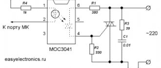
To control the load only in on/off mode, it is advisable to install an optocoupler with a zero detector (for example MOC306x ), it will automatically turn off and turn on the load only when the voltage in the network passes through 0, which greatly reduces interference in the network. There are also resistors here: 220 Ohm - to limit the current to the optocoupler LED (see the characteristics of the optocoupler, I wrote above how to select a resistor). And a resistor between the optocoupler and the triac: 220-470 Ohm with a power of 1-2 W (it will heat up). The triac should be taken with a good current reserve so that it heats up less. Also, triacs come in the BTA and BTB ; the BTA case (metal part) is insulated and it is recommended to take them so as not to be shocked by current from the radiator. Component pinout:
The Chinese have ready-made modules with a triac and all the wiring. By the way, yes, the triac heats up under load! The presence of a radiator is mandatory, starting from 200 Watt.
Triac as a dimmer
To smoothly control an AC load, the task becomes much more complicated: you need to catch the moment the voltage switches, measure the time and turn off the triac, cutting off part of the sinusoid; this is called phase control.
This circuit requires an optocoupler without a zero detector, such as the MOC302x series . The diagram of such a craft might look like this:
51k resistors are necessarily powerful, since 1 Watt will be allocated to them: we extinguish the excess voltage so as not to burn out the LED of the optocoupler of the zero detector. You can also buy a ready-made module on Ali. It looks like this and has power pins, a triac control pin and a zero detector output. How to work with all this - watch the video below:
Somewhere there is a Chinese library for managing such a module, but I didn’t really like it. I give two examples for manual control of such a dimmer based on the GyverTimers library: single-channel and multi-channel. In multi-channel mode, it is enough to connect the zero detector output from only one module to the Arduino, but indicate the control pins in the sketch. The examples discussed below can be slightly optimized by replacing digitalWrite() with a fast analogue.
Single channel is NOT smooth
// example of a dimmer on a triac with an external zero detector // or a ready-made Chinese module https://ali.ski/yGU73N // single-channel dimmer without a timer, works by skipping // half-waves of a sine wave based on interruptions from the zero detector // suitable for motors and heaters, lamps flicker terribly! // Bresenham algorithm https://habr.com/ru/post/254719/ // dimmer takes values 0-255 // switchings are optimized #define ZERO_PIN 2 // zero detector pin #define INT_NUM 0 // corresponding interrupt number # define DIMMER_PIN 4 // triac control pin int dimmer; // dimmer variable void setup() { pinMode(ZERO_PIN, INPUT_PULLUP); pinMode(DIMMER_PIN, OUTPUT); digitalWrite(DIMMER_PIN, LOW); attachInterrupt(INT_NUM, isr, FALLING); // for a homemade circuit, set it to RISING! } void loop() { // set the value 0-255 dimmer = map(analogRead(A0), 0, 1023, 0, 255); delay(100); // in real code there should be no delays } // zero detector interrupt void isr() { static byte count, last, lastVal; int val = ((uint16_t)++count * dimmer) >> 8; if (lastVal != (val != last)) digitalWrite(DIMMER_PIN, val != last); lastVal = (val != last); last = val; }
Multichannel is NOT smooth
// example of a dimmer on a triac with an external zero detector // or a ready-made Chinese module https://ali.ski/yGU73N // multi-channel dimmer without a timer, works by skipping // half-waves of a sine wave based on interruptions from the zero detector // suitable for motors and heaters, lamps flicker terribly! // Bresenham algorithm https://habr.com/ru/post/254719/ // dimmer takes values 0-255 // on-off are optimized #define ZERO_PIN 2 // zero detector pin #define INT_NUM 0 // corresponding interrupt number #define DIM_AMOUNT 3 // number of dimmers const byte dimPins[] = {3, 4, 5}; // their pins int dimmer[DIM_AMOUNT]; // dimmer variable void setup() { pinMode(ZERO_PIN, INPUT_PULLUP); for (byte i = 0; i < DIM_AMOUNT; i++) pinMode(dimPins , OUTPUT); attachInterrupt(INT_NUM, isr, FALLING); // for a homemade circuit, set it to RISING! } void loop() { // set the value 0-255 dimmer[0] = 50; dimmer[1] = 120; dimmer[2] = 190; delay(100); // in real code there should be no delays } // zero detector interrupt void isr() { static byte count, last[DIM_AMOUNT], lastState[DIM_AMOUNT]; count++; for (byte i = 0; i < DIM_AMOUNT; i++) { int val = ((uint16_t)++count * dimmer) >> 8; if (lastState != (val != last )) digitalWrite(dimPins , val != last ); lastState = (val != last ); last = val; } }
Single channel smooth
// example of a dimmer on a triac with an external zero detector // or a ready-made Chinese module https://ali.ski/yGU73N // the GyverTimers library is used (minimum version 1.5) // by analogy you can make a dimmer on any Arduino timer // including among any of the 6 timers for Mega // setPeriod call is optimized #define ZERO_PIN 2 // zero detector pin #define INT_NUM 0 // corresponding interrupt number #define DIMMER_PIN 4 // triac control pin #include // timer library int dimmer ; // dimmer variable void setup() { pinMode(ZERO_PIN, INPUT_PULLUP); pinMode(DIMMER_PIN, OUTPUT); attachInterrupt(INT_NUM, isr, RISING); // for a homemade circuit, set FALLING Timer2.enableISR(); } void loop() { // set the value 500-9300, where 500 is the maximum power, 9300 is the minimum!!! // and 500-7600 for 60 Hz on the network dimmer = map(analogRead(A0), 0, 1024, 500, 9300); delay(100); // in real code there should be no delays } // interrupting the zero detector void isr() { static int lastDim; digitalWrite(DIMMER_PIN, 0); // turn off the triac // if the value has changed, set a new period // if not, then simply restart with the old one if (lastDim != dimmer) Timer2.setPeriod(lastDim = dimmer); else Timer2.restart(); } // timer interrupt ISR(TIMER2_A) { digitalWrite(DIMMER_PIN, 1); // turn on the triac Timer2.stop(); // stop the timer }
Multi-channel smooth
// example of a dimmer on a triac with an external zero detector // or a ready-made Chinese module https://ali.ski/yGU73N // the GyverTimers library is used (minimum version 1.5) // by analogy you can make a dimmer on any Arduino timer // including any of the 6 timers for Mega // multi-channel dimmer. Here is an example with a resolution of 256 (values 0-255) #define ZERO_PIN 2 // zero detector pin #define INT_NUM 0 // corresponding interrupt number #define DIM_AMOUNT 3 // number of dimmers const byte dimPins[] = {3, 4, 5 }; // their pins #include // timer library int dimmer[DIM_AMOUNT]; // dimmer variable volatile int counter = 0; // loop counter void setup() { pinMode(ZERO_PIN, INPUT_PULLUP); for (byte i = 0; i < DIM_AMOUNT; i++) pinMode(dimPins , OUTPUT); attachInterrupt(INT_NUM, isr, FALLING); // for a homemade circuit, set it to RISING Timer2.enableISR(); // 37 µs - interrupt period for 255 steps and 50 Hz // for 60 Hz set the number 31 Timer2.setPeriod(37); Serial.begin(9600); } void loop() { // set the value //dimmer[0] = map(analogRead(A0), 0, 1023, 0, 9500); dimmer[0] = 50; dimmer[1] = 120; dimmer[2] = 190; delay(100); // in real code there should be no delays } // interrupting the zero detector void isr() { counter = 255; Timer2.restart(); } // timer interrupt ISR(TIMER2_A) { for (byte i = 0; i < DIM_AMOUNT; i++) { if (counter == dimmer ) digitalWrite(dimPins , 1); // enable on the current tick else if (counter == dimmer - 1) digitalWrite(dimPins , 0); // turn off next time } counter—; }
Update! I wrapped these algorithms in a class, the GyverDimmer . See description and examples on GitHub.
Solid State Relay (SSR AC)
An AC solid state relay (buy SSR AC) looks and connects exactly the same as a DC solid state relay. The only difference is that there is no polarity:
Compared to an electromagnetic relay, it operates silently and also has an unlimited switching life. But there is also a minus: solid-state relays are based on semiconductor triacs and heat up under load. The lower part of the case is a thick aluminum plate. For heavy loads (several kilowatts), it is advisable to take an SSR with a good current reserve and/or mount it on a radiator. That's it. There are also solid state bodies of a slightly different format in the form of Arduino modules:
Such modules come in low and high level (High/Low level trigger) and are connected in the same way as relay modules: to the GND-VCC power supply and a separate control pin. The SSRs themselves here are small and weak: only 2A (around 500 Watt). But for controlling lighting, for example, this is more than enough. Using a relay, you can smoothly control a highly inertial load, such as a large heater. To do this, you need to use an ultra-low-frequency PWM signal; I have a ready-made library.
Combined method
An electromagnetic relay and a triac (solid-state relay) have disadvantages when working with high currents, which cancel each other out:
- An electromagnetic relay does not work well at the moment of closing and opening the load, because the contacts physically wear out and can generally stick. At the same time, it does not heat up during the flow of high current.
- The triac closes a powerful circuit without problems, sparks or wear, but gets very hot when current flows.
There is a great idea for combining these two devices to switch powerful circuits: a triac (or SSR) is placed in parallel with an electromagnetic relay. First, the circuit is closed by a triac, then after a few milliseconds the relay is closed. That's it, the triac can be turned off, the current will flow through the relay. To disconnect the load, we activate the triac again, turn off the EM relay, and after a few milliseconds turn off the triac. Bingo! If the switching is controlled by a microcontroller, implementing such a circuit is like calling two pins =) You can read about the implementation of an analog circuit (without an MK) on Habré.
Smooth Control (SSR LA)
There is another option for smooth control of an AC load: a solid state relay with built-in phase control and current input, it is called SSR LA. You need to take a relay with an input resistance of around 250 Ohms, so that you can apply 0-5 Volts to it and get the coveted 0-20 mA. I bought these and they work great. To supply 0-5 Volts from Arduino we need a PWM and RC circuit (link to the simulation project in EasyEDA), in the diagram it will look like this:
// Simple example, in which a potentiometer is also connected to A0 void setup() { pinMode(3, OUTPUT); // https://alexgyver.ru/lessons/pwm-overclock/ // Pins D3 and D11 - 8 kHz TCCR2B = 0b00000010; // x8 TCCR2A = 0b00000011; // fast pwm } void loop() { analogWrite(3, analogRead(0) / 4); delay(10); }
DC interference protection
Separate food
One of the best ways to protect against power interference is to power the power and logic parts from separate power supplies: a good low-noise power supply for the microcontroller and modules/sensors, and a separate one for the power part. In stand-alone devices, they sometimes put a separate battery for powering the logic, and a separate powerful one for the power part, because stability and reliability of operation is very important.
DC spark arresting circuits
When the contacts in the power supply circuit of an inductive load open, a so-called inductive surge occurs, which sharply increases the voltage in the circuit to the point that an electric arc (spark) can jump between the contacts of a relay or switch. There is nothing good in an arc - it burns out particles of metal in the contacts, causing them to wear out and become unusable over time. Also, such a jump in the circuit provokes an electromagnetic surge, which can cause strong interference in the electronic device and lead to malfunctions or even breakdown! The most dangerous thing is that the wire itself can be an inductive load: you've probably seen how a regular light switch in a room sparks. A light bulb is not an inductive load, but the wire going to it is inductive. To protect against self-induction EMF surges in a DC circuit, an ordinary diode is used, installed counter-parallel to the load and as close as possible to it. The diode will simply short-circuit the surge, and that’s it:
Where VD is a protective diode, U1 is a switch (transistor, relay), and R and L schematically represent an inductive load. A diode MUST be installed when controlling an inductive load (electric motor, solenoid, valve, electromagnet, relay coil) using a transistor, that is, like this:
When controlling a PWM signal, it is recommended to install high-speed diodes (for example, 1N49xx ) or Schottky diodes (for example, 1N58xx ); the maximum diode current should be greater than or equal to the maximum load current.
Filters
If the power part is powered from the same source as the microcontroller, then power interference is inevitable. The simplest way to protect the MK from such interference is to use power capacitors as close to the MK as possible: electrolyte 6.3V 470 uF (uF) and ceramic 0.1-1 uF, they will smooth out short voltage dips. By the way, an electrolyte with a low ESR will cope with this task as efficiently as possible.
An LC filter consisting of an inductor and a capacitor can handle noise filtering even better. The inductance should be taken with a nominal value in the region of 100-300 μH and with a saturation current greater than the load current after the filter. The capacitor is an electrolyte with a capacity of 100-1000 uF, depending again on the current consumption of the load after the filter. It is connected like this, the closer to the load, the better:
You can read more about calculating filters here.
Fighting noise
Shown in Fig. 3 digital thermostat circuit assumes the presence of ideal mains power. In a real network there is quite strong interference that can affect the functioning of the microcontroller. Particularly dangerous are noises in the megahertz range, the amplitude of which can reach tens of kilovolts. If you take this fact into account when developing a circuit and take a number of simple measures, this will save a lot of effort and time during debugging. Creating a reliable network device involves isolating the microcontroller from high-frequency noise. This applies not only to the power circuits, but also to the rest of the controller outputs. In Fig. Figure 5 shows a modification of the circuit taking into account these recommendations.
Rice. 5. Noise-proof device
The first thing you should pay attention to is the filter on the microcontroller power circuit (C3, R4 and R5). Two “grounds” are obtained - one for the digital part of the circuit, the other for the noisy analog part.
The second is protecting the microcontroller pins using low-pass filters (GP2, GP3). It is recommended to use ceramic capacitors in them.
AC interference protection
Turn off moment
The mains voltage is a sinusoid that crosses the value 0 100 times per second. If you turn off the load at the moment when the mains voltage is zero, this will greatly reduce the surge. For these purposes, the easiest way is to use solid-state relays (SSR) with a zero detector (Zero-Crossing Detector): such relays themselves turn off and turn on the load at the right time. Almost all SSR models have a zero detector, but it is better to check the documentation. For homemade triac switches operating in on/off mode (without dimming), it is recommended to install a control optocoupler with a zero detector: it will also turn the load on and off at the best moment for this, that is, at the nearest zero.
AC spark arresting circuits
EMF surges after disconnecting the load are also present in AC circuits, especially if the load can be switched off at a random time. A voltage surge can manifest itself as a spark between the contacts when the load is turned off, which is bad for the contacts and dangerous in general. To suppress these emissions, snubber circuits consisting of a resistor and a capacitor are used. The theory for calculating spark-extinguishing circuits for alternating current can be found in this article, and for most applications a 39 Ohm 0.5 W resistor and a 0.1 µF 400V capacitor, installed according to this diagram, are suitable:
Also note that some solid-state relays already have a snubber circuit ; you can find out about this from the datasheet for a specific model. It is advisable not to be lazy and install such a circuit on a homemade triac dimmer in order to reduce interference in the network.
Phase control
To change the power supplied to the load through a triac, phase control can be used (Fig. 2). The essence of the method is to skip part of the half-cycle of the mains voltage - similar to pulse width modulation. The current in the load is proportional to the integral of the received signal. This mode is used in dimmers. The brightness of an incandescent lamp is proportional to the area under the trimmed sinusoid.
Rice. 2. Phase control
The advantage of this method is that the ripple frequency at the load remains equal to the network one. This is important for controlling lighting devices, since reducing the frequency can affect the appearance of flickering, noticeable to the eye.
The downside is interference that may appear due to sudden switching of the triac. This interference is bad for the electromagnetic compatibility (EMI) of the resulting device and can cause unnecessary switching of the triac.
Important Pages
- GyverKIT kit - a large Arduino starter kit of my design, sold in Russia
- Catalog of links to cheap Arduins, sensors, modules and other hardware from AliExpress from trusted sellers
- A selection of libraries for Arduino, the most interesting and useful, official and not so
- Complete documentation on the Arduino language, all built-in functions and macros, all available data types
- A collection of useful algorithms for writing sketches: code structure, timers, filters, data parsing
- Video lessons on Arduino programming from the “Arduino Engineer's Notes ” channel are some of the most detailed in RuNet
- Support the author for his work on the lessons
- Feedback - report an error in the lesson or suggest an addition to the text ( [email protected] )
4.8 / 5 ( 24 voices)