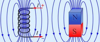
To find the magnetic field induction in the center of a circular conductor with current, it is necessary to divide this conductor into elements, find a vector for each of them, and then add all these vectors. Since all vectors are directed along the normal to the plane of the coil (Fig. 11), the addition of vectors can be replaced by the addition of their modules dB.
According to the Biot-Savart-Laplace law, the vector modulus:
.
Since all elements of the conductor are perpendicular to the corresponding radius vectors, then sina = 1 for all elements. Distances r = R for all conductor elements. Then the expression for the modulus of the vector:
.
Now we can move on to integration:
.
So, the magnetic field induction in the center of a circular conductor with current is:
(R is the radius of the coil with current I).
Application of the Biot–Savart–Laplace law to the calculation of the magnetic field of a circular current
The Biot-Savart–Laplace law describes the generation of a magnetic field by a current $I$ on a conductor element of length $dl$ at a certain point in space ($\mu$ is the magnetic permeability of the substance in which the field is localized):
$d\vec{B}=\frac{\mu_{0}\mu }{4\pi }\frac{I\left[ d\vec{l}\vec{r}\right]}{r^{ 3}}\left( 1 \right)$
where $d \vec l ⃗$ is a vector whose length is equal to the length of the conductor element $dl$, directed along the current; $\vec r$ is the radius vector drawn from the element $dl$ to the point at which the magnetic field is studied. Since the right side of formula (1) contains the vector product, it is obvious that the induction of the elementary magnetic field will be directed perpendicular to the plane in which the vectors $\vec r$ and $\vec l$ are located and at the same time is tangent to the field line.
Are you an expert in this subject area? We invite you to become the author of the Directory Working Conditions
We find the value of the vector $\vec{dB}$ from expression (1) as:
$dB=\frac{\mu_{0}\mu }{4\pi }\frac{Idl\sin \alpha }{r^{2}}\left( 2 \right)$.
where $ \alpha $ is the angle between the vectors $\vec r$ and $\vec l$ .
The specific direction $\vec{dB}$ is found using the gimlet rule (right hand rule):
If the right screw is rotated so that its translational motion coincides with the direction of current flow in the selected element, then the rotation of its head will indicate the direction of $\vec{dB}$.
Magnetic fields obey the principle of superposition:
The total magnetic induction of a field created by several sources is found as the geometric sum of the magnetic induction vectors of individual fields:
$\vec{B}=\sum\limits_{i=1}^N \vec{B}_{i} \left( 3 \right). $
If the current distribution can be considered continuous, then the superposition principle can be written:
$\vec{B}=\int {d\vec{B}_{i}} \left( 4 \right).$
Calculating the magnetic field induction using the Biot-Savart-Laplace law is a rather complicated procedure. But if there is a certain symmetry in the distribution of currents, using the law we have considered and the principle of superposition, it is easy to calculate specific fields. In any case, you should adhere to the following scheme of actions:
Finished works on a similar topic
Course work Magnetic field of circular current 450 ₽ Abstract Magnetic field of circular current 220 ₽ Test work Magnetic field of circular current 250 ₽
Receive completed work or specialist advice on your educational project Find out the cost
- Select an elementary segment $dl$ on the current-carrying conductor.
- Write down the Biot – Savart – Laplace law for the field point under study.
- Determine the direction of the elementary field $\vec{dB}$ at a selected point.
- Use the principle of superposition for magnetic fields (take into account that vectors are summed).
Magnetic flux. Gauss's theorem for magnetic field
The flow of the magnetic induction vector (or magnetic flux) through an arbitrary area S is characterized by the number of magnetic field lines penetrating a given area S.
If the area S is located perpendicular to the magnetic field lines (Fig. 14), then the flux FB of the induction vector through this area S:
.
Rice. 14 Fig. 15
If the area S is located non-perpendicular to the magnetic field lines (Fig. 15), then the flux ФB of the induction vector through this area S:
,
where α is the angle between the vectors and the normal to the area S.
,In order to find the flux FB of the magnetic induction vector through an arbitrary surface S, it is necessary to divide this surface into elementary areas dS (Fig. 16) and determine the elementary flux of the vector through each area dS using the formula:
where α is the angle between the vectors and the normal to a given area dS;
Then the vector flow through an arbitrary surface S is equal to the algebraic sum of elementary flows through all elementary areas dS into which the surface S is divided, which leads to integration:
– a vector equal in size to the area of the site dS and directed along the normal vector to the given site dS.
.
Gauss's theorem for magnetic field
For an arbitrary closed surface S (Fig. 17), the flux of the magnetic field induction vector through this surface S can be calculated using the formula:
.
On the other hand, the number of magnetic induction lines entering the volume bounded by this closed surface is equal to the number of lines emerging from this volume (Fig. 17). Therefore, taking into account the fact that the flux of the magnetic field induction vector is considered positive if the field lines exit the surface S, and negative for the lines entering the surface S, the total flux of the FB vector through an arbitrary closed surface S is equal to zero , i.e.:
,
which constitutes the formulation of Gauss's theorem for the magnetic field .
Magnetic field of a circular current at its center
Figure 1. Magnetic field of a circular current at its center. Author24 - online exchange of student work
Let's consider a circular conductor through which a direct current $I$ flows (Fig. 1). Let us select the element $dl$ on this conductor, which can be considered rectilinear. If we move to another element of the same current, then to the third and so on, applying the rule of the right screw, then it is obvious that all the magnetic fields created by these elements in the center are directed along one straight line, perpendicular to the plane of the ring. This means, using the principle of superposition, we will replace vector addition with algebraic addition.
Let us write the Biot-Savart-Laplace law for the modulus of the field induction vector created by the element d$l_1$:
$dB=\frac{\mu_{0}\mu }{4\pi }\frac{Idl_{1}\sin \alpha }{r^{2}}\left( 5\right).$
From Fig. 1 we see:
- that the distance from the elementary current to the center of the turn is equal to its radius ($R$) and will be the same for all elements on this turn,
- the element $dl$ (like all other elements) will be normal to the radius vector $\vec r$.
Taking into account the said expression (5), we present it in the form:
$dB=\frac{\mu_{0}\mu }{4\pi }\frac{Idl_{1}}{R^{2}}\left( 6 \right)$.
Depersonalizing the turns with current, we further set $dl_1=dl$.
Since our current is continuous, to find the total field at its center, we integrate (6), we have:
$B=\oint\limits_L {dB=} \frac{\mu_{0}\mu }{4\pi}\frac{I}{R^{2}}\oint\limits_L {dl} =\frac{ \mu_{0}\mu }{4\pi}\frac{I}{R^{2}}2\pi R\to$
$B=\mu_{0}\mu \frac{I}{2R}\left( 7 \right)$.
Note 1
$L=2πR$ is the circumference of the coil.
Induction of the magnetic field of a circular current on its axis
Let's find the magnetic field induction on the axis of a circular current if the current flowing through it is equal to $I$, the radius of the turn is $R$ (Fig. 2).
Figure 2. Induction of the magnetic field of a circular current on its axis. Author24 - online exchange of student work
As a basis for accomplishing this task, we will take the Biot-Savart-Laplace law (1), where from Fig. 2 we see that:
- $\vec{r}=\vec{R}+\vec{h}$,
- $d\vec{l}\times \vec{r}=d\vec{l}\times \vec{R}+d\vec{l}\times \vec{h}(9).$
Using the superposition principle, law (1) for our current and formula (8-9) we write:
$\vec{B}=\oint\limits_L {dB=}$$\frac{\mu \mu_{0}}{4\pi }I\oint\limits_L \frac{d\vec{l}\times\ vec{r}}{r^{3}} $ $=\frac{\mu \mu_{0}}{4\pi }\frac{I}{r^{3}}\left( \oint\limits_L {d\vec{l}\times \vec{R}+} \oint\limits_L {d\vec{l}\times \vec{h}}\right)\left( 10 \right).$
In expression (10) when writing the integral, we took into account that the value of the vector $\vec{r}$ does not change. In addition, the vector $\vec h$, which determines the position of the point at which we are looking for the field, does not change when moving along our contour, therefore:
$\oint\limits_L {d\vec{l}\times \vec{h}} =(\oint\limits_L {d\vec{l})\times\vec{h}} =0\, \left( 11 \right),$
since ( $\oint\limits_L{d\vec{l})=0.}$
Let's calculate the integral: $\oint\limits_L {d\vec{l}\times \vec{R}.}$ Let's introduce a unit vector ($\vec n$), normal to the plane of the coil with the current.
$\oint\limits_L {d\vec{l}\times \vec{R}=\oint\limits_L {\vec{n}Rdl=\vec{n}R}} \oint\limits_L {dl=\vec{ n}R} 2\pi R=2\pi R^{2}\vec{n}\left( 12 \right)$.
We substitute the integration results from (12) into (10), we have:
$\vec{B}=\frac{\mu \mu_{0}}{4\pi }\frac{I}{r^{3}}2\pi R^{2}\vec{n}=\ frac{\mu\mu_{0}I}{2}\frac{R^{2}}{\left( R^{2}+h^{2}\right)^{\frac{3}{2 }}}\vec{n}\left( 13 \right)$
where, when recording the final result, we took into account that:
$r^{3}=\left( R^{2}+h^{2} \right)^{\frac{3}{2}}$.
§20. Electromagnetic forces created by a magnetic field
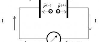
Conductor with current in a magnetic field. The energy contained in a magnetic field can manifest itself in the form of electromagnetic forces, which arise when the magnetic field interacts with moving electric charges. The electromagnetic force that arises when an electric charge moves in a magnetic field acts on it in a direction perpendicular to the movement and direction of the lines of force, and tends to push the charge outside the field (see Fig. 34).
If you place a conductor with current I in a magnetic field, then electromagnetic forces will arise between the electrons passing through the conductor and the magnetic field, which, adding up, form a resultant force F, tending to push the conductor out of the magnetic field (Fig. 48). Electromagnetic force is determined by Ampere's law. It is formulated as follows. The electromagnetic force acting on a current-carrying conductor located in a magnetic field and located perpendicular to the direction of the field is equal to the product of the current strength I, the magnetic field induction B and the length of the conductor l:
F = IB l (48)
If the conductor is located at an angle? to power magnetic
F = BI l sin? (48′)
To get F in newtons, you need to take B in teslas, I in amperaxes and l in meters.
The direction of action of the force F is usually determined by the rule of the left hand: the palm of the left hand must be positioned so that the magnetic lines enter it and the four outstretched fingers should be aligned with the direction of the current, then the thumb located at a right angle will indicate the direction of action of the electromagnetic force. Force F occurs only if the conductor is located perpendicular or at some angle to the magnetic field lines. If the conductor is located along the field lines, then the electromagnetic force will be zero.
In order to change the direction of the electromagnetic force, as follows from the left-hand rule, it is necessary to change the direction of the current in the conductor or the direction of the magnetic field.
The emergence of electromagnetic force F during the interaction of a conductor with current and a magnetic field can be clearly represented as the result of the interaction of two magnetic fields. As is known, around a current-carrying conductor its own circular magnetic field arises (Fig. 49), which will add up to the external magnetic field (for example, a permanent magnet) in which the current-carrying conductor is placed. In this case, to the right of the conductor, where the field lines of the conductor coincide with the lines of the external field, the field lines become thicker; to the left of the conductor, where the field lines of the conductor are directed towards the lines of the external field, rarefaction of the field lines occurs. Magnetic lines of force have elastic properties reminiscent of rubber threads. Trying to shorten in length, they will push the conductor out of the area of concentration of the lines of force towards their rarefaction, i.e. from right to left. As a result, an electromagnetic force F arises.
Rice. 48. Electromagnetic force acting in a magnetic field on a current-carrying conductor
Rice. 49. Condensation and rarefaction of magnetic field lines in the presence of a current-carrying conductor in a magnetic field.
Rice. 50.Electromagnetic forces acting in a magnetic field on a turn or coil with current.
A coil with current in a magnetic field. If we place in a magnetic field not a conductor, but a coil (or coil) with current and position it vertically (Fig. 50, a), then, applying the left-hand rule to the upper and lower sides of the coil, we obtain that the electromagnetic forces F acting on them will be directed in different directions. As a result of the action of these two forces, an electromagnetic torque M arises, which will cause the coil to rotate, in this case clockwise. This moment
M = FD (49)
where D is the distance between the sides of the coil. The coil will rotate in the magnetic field until it takes a position perpendicular to the magnetic field lines (Fig. 50, b). In this position, the greatest magnetic flux will pass through the coil. Consequently, a coil or coil with current introduced into an external magnetic field always tends to take a position such that the greatest possible magnetic flux passes through the coil. The property of a turn and coil with current to rotate in a magnetic field is widely used in electrical engineering; Electric motors and a number of electrical measuring instruments operate on this principle.
To increase torque in electric motors, not one turn is used, but several. These turns, suitably connected, form the armature winding of the electric motor.
Magnetic voltage.
By analogy with electric voltage, when calculating magnetic fields, the concept of magnetic voltage U m . The magnetic voltage between two points a and b of a uniform magnetic field located on the same magnetic line (Fig. 2, a) is expressed by the product of the field strength and the distance between these points: In a more general case, if in a uniform field two points a and b are located at a distance L not on the same magnetic line (Fig. 2, b), the intensity H is first calculated, then the longitudinal component of the intensity vector along the segment ab, i.e. HL = H cosa, where a is the angle between the vectors H and HL. Magnetic voltage In a non-uniform magnetic field, the magnetic voltage between two points a and b is equal to the sum of the elementary voltages HLdL in the elementary sections dL along the selected path between these points (Fig. 2, c):
The magnetic voltage Um may depend on the chosen path between the starting and ending points. Magnetic voltage in the SI system is measured in amperes:
Magnetic stress along an arbitrary closed path (circuit) is the MMF along this circuit. Thus, the MMF can be defined as the sum of elementary magnetic stresses HLdL along a closed loop: where the sign denotes the summation (integration) of elementary stresses HLdL along a closed loop.