ON TECHNICAL REGULATION AND METROLOGY
GOST R 50571.5.54-n l cio n l l ny 2013/
IEC 60364-5-54:2011
STANDARD
RUSSIAN
FEDERATION
LOW-VOLTAGE ELECTRICAL INSTALLATIONS Part 5-54 Selection and installation of electrical equipment Grounding devices, protective conductors and protective potential equalization conductors
IEC 60364-5-54:2011 Low-voltage electrical installations.
Part 5-54: Selection and erection of electrical equipment. Earthing arrangements, protective conductors and protective bonding
conductors
(IDT)
Official publication
| Moscow Standardinform 2014 |
Designation on electrical diagrams
When developing design documentation, a large number of electrical circuits are drawn. All parts are indicated by special symbols, including grounding systems.
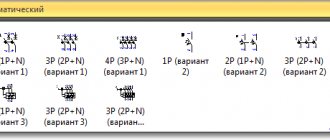
Regulatory documents define several types of images, of which four types are used most often in diagrams:
- The first picture contains one vertical and three horizontal lines. This sign is the main one in many electrical circuits and has been used from past years to the present day. Indicates the connection of the circuit to the grounding conductor.
- The second grounding symbol is similar to the previous one. However, unlike the first one, it is located in a circle and has a shortened pattern. Applied to separately installed equipment excluded from the general protection system of other electrical installations. Essentially, it means an individual connection to the ground loop and connection to the ground.
- Sign No. 3 looks a little like a rake and corresponds to the grounding made through the device body. Provides only partial protection against electric shock.
- The fourth designation of grounding is rarely used and means a protective connection to live parts that are not energized.
Electrical safety posters and signs
Ground wire: cross-section, marking and color
Ground bus
What is grounding
Grounding and grounding of electrical installations
Grounding systems TN-C, TN-S, TNC-S, TT, IT
GOST P 50571.5.54-2013
k is a coefficient depending on the material of the protective conductor, insulation, adjacent parts, initial and final temperatures (calculation of k, see Appendix A).
Notes
1 The current limit due to the circuit impedance and the limitation of ti by the protective device should be taken into account.
2 Instructions for limiting temperatures in explosive atmospheres are given in
3 For cables with mineral insulation [9], in the case where the short-circuit current resistance of the metal sheath of the cable is greater than that of the circuit conductors, it is not necessary to calculate the cross-section of the metal sheath used as a protective conductor.
543.1.3 The cross-section of any protective conductor that is not a cable core or is not laid in a common sheath with the circuit conductors,
should be no less than:
2 *>
- 2.5 mm * C or 16 mm "A1, if there is mechanical protection,
- 4 mm2 С or 16mm2А1, if there is no mechanical protection. Note—This does not exclude the possibility of using steel in
as a protective conductor (see 543.1.2).
A protective conductor that is not part of the cable is considered mechanically protected if it is laid in a pipe, box or other similar method.
543.1.4 If the protective conductor is common to two or more circuits, then its cross-section is selected as follows:
— calculated in accordance with 543.1.1, based on the maximum expected short-circuit current and circuit disconnection time or;
- selected according to table 54.2 in relation to the circuit with the maximum cross-section of the circuit conductors.
543.2 Types of protective conductors
543.2.1 Protective conductors may be one of the following types or a combination thereof:
— conductors (cores) of a multicore cable;
GOST P 50571.5.54-2013
- an insulated or bare conductor, which is laid in a common sheath with working conductors;
— permanently laid bare or insulated conductors;
- metal cable sheaths, cable screens, cable armor, wire braiding, concentric conductors, metal pipes, objects that meet the provisions of listings a) and b) 543.2.2.
Note—See 543.8 for their location.
543.2.2 If the installation contains low-voltage protective and control devices (see IEC 61439-1 and IEC 61439-2) or busbar trunking (see IEC 60439-2), their metal sheaths or frames may be used as protective conductors for simultaneous fulfillment of the following conditions:
a) electrical continuity is provided by the design or installation of additional jumpers in such a way that protection against mechanical, chemical and electrochemical damage is provided;
b) they comply with the requirements of 543.1;
c) provision shall be made for connecting other protective conductors at specified points.
543.2.3 The following metal parts shall not be used as protective conductors and protective potential equalization conductors:
— pipes of water supply systems;
— pipelines with flammable gases and liquids.
Note 1 For cathodic protection, see 542.2.6;
— structures subject to mechanical loads under normal conditions;
- flexible or soft conductors, with the exception of those specifically intended for these purposes;
flexible parts;
15
— supporting structures for electrical wiring, cable trays and cable ladders.
NOTE 2 Examples of protective conductors, including protective equipotential bonding conductors, protective earthing conductors and earthing conductors, apply when they are used for protection against electric shock.
Directional posters
A typical representative of this group is the “GROUNDED” sign. It indicates the grounding of a certain section of the electrical installation and the prohibition of the supply of electric current to it.
Its location is usually the drive of the switching equipment. If prohibition and directional posters are used at the same time, the latter should be hung from above. Dimensions according to GOST 100x200 or 50x100 mm, with a corresponding white border width of 13 and 5 mm. The inscription uses white letters located on a blue background.
Grounding sign
Electrical safety group 2
5 electrical safety group
Electrical safety group 4
Electrical safety approval groups
Electrical safety group 3
GOST R 50571.5.54-2013
NOTE If the lightning protection system is connected to an earthing conductor, the cross-sectional area of the earthing conductor should be at least 16 mm' for copper (Cu) or 50 mm' for iron (Fe) (see IEC 62305 series).
542.3.2 The connection of the grounding conductor to the grounding electrode must be reliable and with appropriate electrical characteristics. The connection can be made by welding, crimping, connecting clamp or other mechanical connector. The mechanical connection must be installed in accordance with the manufacturer's instructions. Installation of the connection clamp must not result in damage to the electrode or grounding conductor.
Soldered joints or soldered parts that rely solely on solder should not be used on their own as they do not provide the required mechanical strength.
Note - If vertical electrodes are used, it must be possible to control the connection and replace the vertical rod.
Dimensions of the grounding sign according to GOST 21130-75
The specified GOST specifies not only the dimensions, but also the methods of applying the sign on the equipment of the manufacturer of panels and other electrical equipment. 4 types of designation are regulated:
- Stamping method.
- Casting in steel case.
- Impact method.
- Pressing method in plastic cases.
Clause 3.1 of the above GOST specifies the possibility of making signs using appliqué, paint, or photochemical methods. The only strict requirement is their size:
When casting or pressing on the body
| H | H1 | D* | b | h | r |
| 5 | 3,6 | 10 | 0,7 | 2,5 | 0,35 |
| 8 | 6,0 | 16 | 1,2 | 4,0 | 0,6 |
| 10 | 7,0 | 20 | 1,4 | 5,0 | 0,7 |
| 14 | 9,0 | 25 | 1,8 | 5,5 | 0,9 |
| 22 | 15,0 | 40 | 3,0 | 9,0 | 1,5 |
| 28 | 17,5 | 45 | 3,5 | 8,5 | 1,75 |
| 30 | 20,0 | 50 | 4,0 | 10,0 | 2,0 |
| 50 | 35,0 | 90 | 7,0 | 20,0 | 3,5 |
When manufactured using the impact method
| D | H | H1 | b | h | r |
| 14 | 8 | 6,0 | 1,2 | 2,5 | 0,6 |
| 18 | 10 | 7,0 | 1,4 | 5,0 | 0,7 |
| 25 | 14 | 9,0 | 1,8 | 5,5 | 0,9 |
What does a grounding sign look like?
The grounding sign (ЗЗ) appears as a black symbol on a bright yellow background. The logo icons must be located next to the grounding bus mount. According to GOST ZZ, they must have a certain type of execution. Methods for applying and installing glazing can be completely different.
Metal plate
The manufacturer itself installs a logo on its products in the form of a convex or depressed image on a metal plate. The plaque is either screwed on or welded using spot welding.
Sticky symbols
GOST does not prohibit the use of stickers. Typically, these emblems have an adhesive backing. Remove the protective film from the back of the sign and press it to the clean surface of the body in the right place. The sticker must be ironed with a rag or a clean cloth so that no air bubbles remain under the sign. If this is not done, the sticker may come off over time.
Sticker near the bus terminals
Adhesive signs are made using high quality materials. This allows them to be used in conditions of significant vibration and high humidity levels.
Cast images
When manufacturing a flask for casting housings of electrical devices, the manufacturer inserts a template with a grounding logo into the casting mold. ZZ is obtained in the form of a relief imprint on the body of the equipment casing.
In this case, the sign is painted by hand with black and yellow enamel. The painted surface is periodically updated. GOST 21130-75 prescribes a clear execution of the design, indicating the detailed dimensions of the design elements. This applies not only to metal, but also to plastic cases made by injection molding.
Dimensions ZZ
Stamp
Drawing images using the stamping method has been used for quite some time. Most often, the method is used in the manufacture of non-ferrous metal cases. The dimensions of the stamped ground symbol detail are slightly different from the cast ones. They are indicated in the table of the same GOST 21130-75: this is the diameter of the circle, the length and thickness of the lines, the angles of the figure, etc.
Important! In both cases, the edging of the circle and the logo itself are most often painted with radical black paint, while the field of the sign itself is bright yellow or orange.
GOST P 50571.5.54-2013
Appendix D provides methods for estimating the resistance of ground electrodes.
542.2.3 The following can be used as grounding conductors: foundation grounding conductors embedded in concrete
electrodes;
NOTE For further information see Annex C;
— foundation grounding electrodes buried in the ground;
- metal electrodes buried directly in
soil vertically or horizontally (for example, rods,
wire, tape, pipe or strip);
— metal sheaths or other metal coverings of cables in accordance with local conditions or requirements;
* other buried metal products in accordance with local conditions or requirements.
- metal reinforcement of reinforced concrete (with the exception of stressed reinforced concrete) located in the ground.
542.2.4 When selecting the type and depth of installation of grounding electrodes, the possibility of mechanical damage and minimizing the effects of drying or freezing of the soil shall be taken into account.
542.2.5 When using different materials in grounding devices, the possibility of electrical corrosion must be provided for. For external conductors (for example, grounding) connected to foundation grounding electrodes embedded in concrete, the connection made of hot-dip galvanized steel should not be in the ground.
542.2.6 Metal pipelines with flammable liquids and gases should not be used as grounding conductors; the part laid in the ground should not be taken into account when calculating the parameters of grounding conductors.
9
GOST P 50571.5.54-2013
NOTE This does not exclude the need to include them in the potential equalization system, like pipes in accordance with the instructions of IEC 60364-4-41 (clause 541.3.9).
In a CT protective grounding system, where cathodic protection is used and third-party conductive parts of electrical equipment are directly connected to metal pipes for flammable liquids or gases, the latter can be used as the only grounder for this equipment.
542.2.7 Grounding electrodes shall not be directly immersed in the water of a stream, river, pond, lake, etc. (See also 542.1.6).
542.2.8 If the earthing conductor consists of parts that are to be joined together, the connection shall be made by exothermic welding, crimping, clamping, or other approved mechanical connector.
Note—Connections made with iron-coated wire are not permitted for protection purposes.
542.3 Grounding conductors
542.3.1 Grounding conductors shall meet the requirements
543.1.1 or 543.1.2. Their cross-sectional area must be at least 6 mm2 for copper or 50 mm2 for steel. If a bare grounding conductor is laid in the ground, its dimensions and characteristics must correspond to those specified in Table 54.1.
When it is confirmed that the fault current cannot flow to the grounding electrode (for example, in a TN or IT protective earthing system), the grounding conductors may be selected in accordance with the guidelines of 544.1.
Aluminum conductors should not be used as grounding conductors.
V(V)
| Damn 2 | ||||||||||||||||||||||||||||
| An example of a symbol for a contact washer for a stud with a diameter of 5 mm: Contact washer 5 GOST 21130-75 (Changed edition, Amendment No. 2, 4, 5). 1.2.2. The material of the contact washer is brass grade L63 according to GOST 15527-70. 1.2.3. The contact washer coating is 09 or M9 according to GOST 9.306-85. (Changed edition, Amendment No. 4). 1.3. The design and dimensions of type ZB clamps must correspond to those indicated in Fig. 3 and in table. 3. Version 2
|
General information about electrical safety signs
Electrical safety posters and signs are produced according to established standards. They are intended for use in various conditions and are divided into several categories:
- Prohibiting. These posters prohibit any actions with switching equipment, the activation of which by mistake may cause voltage to enter the workplace. They also prohibit moving without protective equipment in electrical installations with a voltage of 330 kV or more and an electric field strength of over 5 kV/m.
- Warning. Electrical safety signs in this category warn of possible danger when approaching live parts in electrical installations that are energized.
- Prescriptive. Allow the performance of any actions subject to specific electrical safety requirements.
- Pointing. They indicate the location of certain objects and devices.
In accordance with the nature and characteristics of the application, all graphic images in the field of electrical safety are of permanent or portable type.
Posters and safety signs are attached to metal or concrete surfaces with great difficulty for technical reasons. Therefore, it is recommended to apply them through a stencil with appropriate paints or stick posters on the basis of self-adhesive film. The paint and varnish materials used must provide a color coating that is resistant to the production and climatic conditions for which they are intended.
In order to better understand the purpose of each category of posters and signs, they need to be considered in more detail. Their correct and timely use will help protect personnel from accidents and preserve people’s lives and health.
Preface
The goals and principles of standardization in the Russian Federation are established by the Federal Law of December 27, 2002 X° 184-FZ “On Technical Regulation”
1 PREPARED by the Moscow Institute of Energy Security and Energy Saving on the basis of an authentic translation into Russian of the international standard specified in paragraph 4
2 INTRODUCED by the Technical Committee for Standardization TC 337 “Electrical installations of buildings”
3 APPROVED AND ENTERED INTO EFFECT by Order of the Federal Agency for Technical Regulation and Metrology dated September 6, 2013 No. 976-st
4 This standard is identical to the international standard IEC 60364-5-54:2011 “Electrical installations of buildings. Part 5-54. Selection and installation of electrical equipment. Grounding arrangements and protective conductors" (IEC 60364-5-54:2011 Low-voltage electrical installations. Part 5-54: Selection and erection of electrical equipment. Earthing arrangements and protective conductors).
The title of this standard has been changed from the title of this international standard to align it with the newly adopted title of the IEC 60364 series of standards.
When applying this standard, it is recommended to use, instead of reference international standards, the corresponding national standards of the Russian Federation, information about which is given in Additional Appendix DA..
5 Instead of GOST R 50571.5.54-2011 (IEC 60364-5-54:2002)
The rules for applying this standard are established in GOST R 1.0-2012 (section 8). Information about changes to this standard is published in the annual (as of January 1 of the current year) information index “National Standards”, and the text of changes and amendments in the monthly index “National Standards”. In case of revision (replacement) or cancellation of this standard, the corresponding notice will be published in the next issue of the monthly information index “National Standards”.
Relevant information. the notification and texts are also posted in the public information system - on the official website of the national body of the Russian Federation for standardization on the Internet (gost.ru)
About Standardinform, 2013 This standard cannot be fully or partially reproduced, replicated and distributed as an official publication without permission from the Federal Agency for Technical Regulation and Metrology
Content
Options for marking electrical equipment
Most often, a symbol or letter designation is applied to the shields or control panels directly at the manufacturer. The designation location has a convex or depressed relief surface. On new production lines, the “grounded” sign on the shields is cast directly during the manufacture of the metal or plastic housing.
Regardless of whether there is an embossed marking or not, the ground symbol is additionally colored for visual highlighting on the surface of the housing.
For old electrical appliances, production usually simply uses a grounding sign sticker, which is glued to a special adhesive compound or using adhesive tape. As a result, it is possible to quickly mark all the panels and significantly save money. It is worth noting that the use of a grounding symbol in the form of a sticker does not contradict the current GOST.
Which places are indicated by a grounding sign?
As you know, the main purpose of grounding is to ensure electrical safety. And the main purpose of the grounding sign is to indicate the specific place where the equipment is connected to the grounding loop.
Where is it customary to put symbols indicating the connection of the equipment with the “ground”? First of all, these are the places where the protective conductors are connected to the main grounding buses, near the terminals or studs for connecting the protective conductor.
Friends, let's figure out where grounding signs are installed in electrical installations, according to the rules and GOST.
The first regulatory document that says about applying the grounding sign GOST R 51778-2001 “Distribution panels for industrial and public buildings” Clause 6.4.6 of this document says that the grounding sign should be applied near the grounding terminal, as well as near the terminal where the neutral protective one is connected conductor - PE.
The next regulatory document is GOST 12.2.007.0-75 ELECTRICAL PRODUCTS. General safety requirements. Paragraph 3.3.5 states that an indelible (implied during operation) grounding sign must be applied in any way near the connection point of the grounding conductor. By the way, the same paragraph says that the place for connecting the grounding conductor must be cleaned of corrosion, and the connected area (sleeve) must not have surface paint.
Regarding cleaning from corrosion, I think this is a very important note. I personally spent a long time looking for where this action is written.
Let's go further - PB 08-624-03 “Safety Rules in the Oil and Gas Industry.” Clause 1.5.14 states that the “grounding” symbol must be depicted in the place where the metal parts of the equipment are connected to the PE protective conductor.
And of course, let’s not forget about our native PUE. Paragraphs 1.7.118 and 1.7.119 of which also stipulate the application of grounding identification marks.
Image Features
The main document regulating the designation of grounding is GOST 21130-75. It specifies the location of application and features of the image depending on the type of equipment, as well as its dimensions.
According to GOST requirements, this image is applied to the body of electrical equipment near the point where the grounding cable is connected to the device. Additionally, the image must be applied next to the terminal for connecting the neutral protective conductor (PE). Also, the grounding symbol must be depicted inside the electrical panel to which electrical installations or wiring are connected.
The grounding symbol on the equipment can be applied with paint, in the form of a sticker, engraved on the case, or made in any other way to ensure its preservation during the operation of the product. That is, the image must be indelible and positioned in such a way as to avoid damage or blurring.
In addition to marking contacts on electrical installations, it is recommended to mark the locations of grounding loops.
Additionally, letters indicating the type of grounding may be shown next to it.
Systems with solidly grounded neutral (TN grounding systems)
This is the designation of systems in which a common solidly grounded neutral of a generator or step-down transformer is used to connect neutral functional and protective conductors. In this case, all electrically conductive housing parts and consumer screens should be connected to a common neutral conductor connected to this neutral. In accordance with GOST R50571.2-94, neutral conductors of various types are also designated in Latin letters:
- N – functional “zero”;
- PE - protective “zero”;
- PEN is a combination of functional and protective neutral conductors.
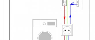
Constructed using a solidly grounded neutral, the TN grounding system is characterized by connecting the functional “zero” - conductor N (neutral) to a grounding loop equipped next to the transformer substation. Obviously, in this system, grounding of the neutral through a special compensating device - an arc suppression reactor - is not used. In practice, three subtypes of the TN system are used: TN-C, TN-S, TN-CS, which differ from each other in different ways of connecting the neutral conductors “N” and “PE”.
TN-C grounding system
TN-C grounding system
As follows from the letter designation, the TN-C system is characterized by the combination of functional and protective neutral conductors. The classic TN-C system is a traditional four-wire power supply circuit with three phase and one neutral wire. The main grounding bus in this case is a solidly grounded neutral, to which all open parts, housings and metal parts of devices capable of conducting electric current must be connected with additional neutral wires.
This system has several significant drawbacks, the main one of which is the loss of protective functions in the event of a break or burnout of the neutral wire. In this case, life-threatening voltage will appear on the uninsulated surfaces of the housings of devices and equipment. Since a separate protective grounding conductor PE is not used in this system, all connected sockets are not grounded. Therefore, the electrical equipment used has to be grounded - the housing parts must be connected to the neutral wire. .
If, with such a connection, the phase wire touches the housing, an automatic fuse will trip due to a short circuit, and the danger of electric shock to people or fire of sparking equipment will be eliminated by a quick emergency shutdown. An important restriction when forced to neutralize household appliances, which everyone living in rooms powered by the TN-C system should be aware of, is the prohibition of using additional potential equalization circuits in bathrooms.
Currently, this grounding system has been preserved in houses belonging to the old housing stock, and is also used in street lighting networks, where the degree of risk is minimal.
TN-S system
Grounding system TN-S
A more progressive and safer system compared to TN-C with separated working and protective zeros TN-S was developed and implemented in the 30s of the last century. With a high level of electrical safety for people and equipment, this solution has one, but quite significant, drawback - high cost. Since the separation of the working (N) and protective (PE) zero is implemented immediately at the substation, three-phase voltage is supplied through five wires, single-phase - through three. To connect both neutral conductors on the source side, a solidly grounded neutral of the generator or transformer is used.
GOST R50571 and the updated version of the PUE contain a requirement for the installation at all critical facilities, as well as buildings under construction and major repairs, of power supply based on the TN-S system, which ensures a high level of electrical safety. Unfortunately, the wide dissemination and implementation of the TN-S system is hampered by the high level of costs and the focus of the Russian energy sector on four-wire three-phase power supply circuits.
TN-CS system
Grounding system TN-CS
In order to reduce the cost of the safety-optimal, but financially intensive TN-S system with separated neutral conductors N and PE, a solution was created that allows you to use its advantages with a smaller budget, slightly exceeding the cost of power supply through the TN-C system. The essence of this connection method is that electricity is supplied from the substation using a combined zero “PEN” connected to a solidly grounded neutral. Which, at the entrance to the building, branches into “PE” - a protective zero, and another conductor that performs the function of the working zero “N” on the consumer side.
This system has a significant drawback - in the event of damage or burnout of the PEN wire in the substation-building section, dangerous voltage will appear on the PE conductor, and, consequently, on all associated housing parts of electrical appliances. Therefore, when using the TN-CS system, which is quite common, regulations require special measures to protect the PEN conductor from damage.
TT grounding system
TT grounding system
When supplying electricity via a traditional overhead line in rural and suburban areas, if an unsafe TN-CS system is used here, it is difficult to ensure adequate protection of the PEN combined ground conductor. The TT system is increasingly being used here, which involves “solid” grounding of the source neutral and transmission of three-phase voltage through four wires. The fourth is the function zero "N". On the consumer side, a local, usually modular-pin grounding switch is installed, to which all PE protective earth conductors connected to the housing parts are connected.
Most recently approved for use on the territory of the Russian Federation, this system quickly spread in the Russian outback to supply energy to private households. In urban areas, TT is often used to electrify temporary retail and service outlets. With this method of grounding, a prerequisite is the presence of residual current devices, as well as the implementation of technical lightning protection measures.
Location on the equipment
Depending on the type of electrical equipment, GOST standardizes the marking option and the place on the housing where the connection to ground should be indicated:
- Grounding symbol near the clamp/clip on the shield. According to paragraph 6.4.6 of GOST R 51778 of 2001, the designation must be located at the clamp. Additionally, a sign marks the place where the neutral protective conductor PE is connected.
- “Grounded” sign next to the connection between the metal parts of the housing and the PE conductor. The option is due to the requirements of safety rules 08-624-03. A sticker can be glued to the case or the corresponding symbol can be engraved directly into the metal.
GOST P 50571.5.54-2013
The minimum dimensions of grounding electrodes made of the most common materials in terms of corrosion and mechanical resistance, laid in the ground and embedded in concrete are given in Table 54.1.
Note 2 The minimum thickness of the protective coating should be greater for vertical ground electrodes than for horizontal ground electrodes due to the greater mechanical stress when they are buried.
If lightning protection systems are required, then IEC 62305-3 (subsection 5.4) is used.
7
| GOST P 50571.5.54-2013 Table 54.1 - Minimum dimensions of grounding electrodes laid in the ground from the most common materials in terms of corrosion and mechanical resistance |
| 542.2.2 The effectiveness of a particular grounding electrode depends on the nature of the soil. The number of grounding electrodes is selected depending on the nature of the soil and its resistance. |
Designation methods
There are several options for how grounding is designated. In the case of the manufacture of cast parts for electrical equipment, it is cast together with metal or plastic parts. Previously, the option of manufacturing by stamping or by embossing was often used. Thus, the grounding sign on the equipment was either convex or concave, depending on the side from which it was applied.
The use of stickers with the image of the grounding sign does not contradict the requirements of GOST(r) 51778-200. The main requirement for stickers with the image of a grounding sign is to ensure their visibility and maintain the quality of the design for a long time. To prevent the sticker from coming off over time, it is recommended to stick it on a clean, flat surface. During the gluing process, it is necessary to carefully level the sticker, removing all the air from under it. If the sticker does not have an adhesive layer on the back of the image, it is fixed with transparent adhesive tape.
Graphic options
The grounding icon on drawings and electrical circuit diagrams is regulated by GOST 2.721-74 and the unified system of design documentation (ESKD). These regulatory documents describe how grounding is designated in electrical engineering, as well as the location where equipment is connected to the ground loop. Its dimensions, proportions and methods of depiction are also specified.
Depending on the type and features of connecting the electrical installation to the circuit, there are 4 main ways to indicate grounding in the diagram:
- One vertical line and 3 horizontal lines, located one below the other, each subsequent horizontal line is smaller than the previous one, this option is a standard image of grounding;
- The second option differs from the first in the incomplete circle in which the sign is enclosed; it is used to indicate the connection to the “ground” of separate electrical installations that are not included in the common ground loop;
- In the third case, the circle described around the sign is complete; this option denotes a connection to a common grounding bus of live parts that are not energized under normal conditions;
- The last version of the grounding symbol resembles a rake and indicates the connection of the device to the ground loop through its body.
How is grounding indicated in diagrams and drawings?
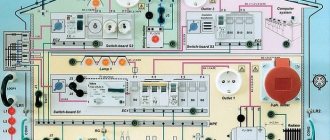
When designing electrical circuits on a production line, not only structural elements, switching devices and control equipment are marked, but also the location of the ground loop.
The regulatory document, which specifies all the features of the sign designation on the diagrams, is GOST 2.721 of 1974. Designation of a silent and protective version of grounding signs in the drawings
Important! To select the correct symbol, special attention must be paid to the characteristics of the equipment to be grounded. Depending on the type of grounding, alphabetic symbols (N, PE, PEN) are added to the icon.
Location on the equipment
Depending on the type of electrical equipment, GOST standardizes the marking option and the place on the housing where the connection to ground should be indicated:
- Grounding symbol near the clamp/clip on the shield. According to paragraph 6.4.6 of GOST R 51778 of 2001, the designation must be located at the clamp. Additionally, a sign marks the place where the neutral protective conductor PE is connected.
- “Grounded” sign next to the connection between the metal parts of the housing and the PE conductor. The option is due to the requirements of safety rules 08-624-03. A sticker can be glued to the case or the corresponding symbol can be engraved directly into the metal.
Important! The grounding sign is applied to the surface of the electrical panel in any indelible way. The junction of the grounding cable and the shield itself is cleaned of corrosion, and some of the paint is removed from the connected area
Image Features
The main document regulating the designation of grounding is GOST 21130-75. It specifies the location of application and features of the image depending on the type of equipment, as well as its dimensions.
According to GOST requirements, this image is applied to the body of electrical equipment near the point where the grounding cable is connected to the device. Additionally, the image must be applied next to the terminal for connecting the neutral protective conductor (PE). Also, the grounding symbol must be depicted inside the electrical panel to which electrical installations or wiring are connected.
The grounding symbol on the equipment can be applied with paint, in the form of a sticker, engraved on the case, or made in any other way to ensure its preservation during the operation of the product. That is, the image must be indelible and positioned in such a way as to avoid damage or blurring.
In addition to marking contacts on electrical installations, it is recommended to mark the locations of grounding loops.
Additionally, letters indicating the type of grounding may be shown next to it.
What does a grounding sign look like?
Grounding circuit: PUE standards
The grounding sign (ЗЗ) appears as a black symbol on a bright yellow background. The logo icons must be located next to the grounding bus mount. According to GOST ZZ, they must have a certain type of execution. Methods for applying and installing glazing can be completely different.
Metal plate
The manufacturer itself installs a logo on its products in the form of a convex or depressed image on a metal plate. The plaque is either screwed on or welded using spot welding.
Sticky symbols
GOST does not prohibit the use of stickers. Typically, these emblems have an adhesive backing. Remove the protective film from the back of the sign and press it to the clean surface of the body in the right place. The sticker must be ironed with a rag or a clean cloth so that no air bubbles remain under the sign. If this is not done, the sticker may come off over time.
Adhesive signs are made using high quality materials. This allows them to be used in conditions of significant vibration and high humidity levels.
Cast images
When manufacturing a flask for casting housings of electrical devices, the manufacturer inserts a template with a grounding logo into the casting mold. ZZ is obtained in the form of a relief imprint on the body of the equipment casing.
In this case, the sign is painted by hand with black and yellow enamel. The painted surface is periodically updated. GOST 21130-75 prescribes a clear execution of the design, indicating the detailed dimensions of the design elements. This applies not only to metal, but also to plastic cases made by injection molding.
Stamp
Drawing images using the stamping method has been used for quite some time. Most often, the method is used in the manufacture of non-ferrous metal cases. The dimensions of the stamped ground symbol detail are slightly different from the cast ones. They are indicated in the table of the same GOST 21130-75: this is the diameter of the circle, the length and thickness of the lines, the angles of the figure, etc.
Important! In both cases, the edging of the circle and the logo itself are most often painted with radical black paint, while the field of the sign itself is bright yellow or orange.
Other GOSTs
GOST 23088-80 Electronic products. Requirements for packaging, transportation and test methods GOST 21493-76 Electronic products. Storability requirements and test methods GOST 20271.3-91 Microwave electronic products. Methods for measuring modulating pulse parameters GOST 20271.1-91 Microwave electronic products. Methods for measuring electrical parameters GOST 15963-79 Electrical products for areas with tropical climates. General technical requirements and test methods GOST 17412-72 Electrical products for areas with cold climates. Technical requirements, acceptance and test methods GOST 19348-82 Electrical products for agricultural purposes. General technical requirements. Labeling, packaging, transportation and storage GOST 24682-81 Electrical products. General technical requirements regarding resistance to special media GOST 14254-80 Electrical products. Shells. Degree of protection. Notation. Test methods GOST 24683-81 Electrical products. Methods for monitoring resistance to special media GOST 16962.1-89 Electrical products. Test methods for resistance to external climatic influences GOST 16962.2-90 Electrical products. Test methods for resistance to mechanical external influences GOST 18620-86 Electrical products. Marking GOST 15543-70 Electrical products. Versions for different climatic regions. General technical requirements regarding the impact of environmental climatic factors
Regulations
home
-Regulations
Lightning Protection and Grounding
PUE Rules for electrical installations
SO 153-34.21.122-2003 Instructions for the installation of lightning protection of buildings, structures and industrial communications
RD 34.21.122-87 Instructions for the installation of lightning protection of buildings and structures
GOST R IEC 62305-1-2010 Risk management. Lightning protection. Part 1. General principles
GOST R IEC 62305-2-2010 Risk management. Lightning protection. Part 2: Risk assessment
GOST R 50571.5.54-2013 Low-voltage electrical installations. Part 5-54 Selection and installation of equipment. Grounding devices and protective conductors
GOST 57190-2016 Grounding conductors and grounding devices for various purposes. Terms and Definitions
GOST R 62561.2-2014 Components of lightning protection systems. Part 2. Requirements for conductors and grounding electrodes
GOST R 50571.22-2000 Electrical installations of buildings. Part 7. Requirements for special electrical installations. Section 707. Grounding of Information Processing Equipment
GOST 464-79 Grounding for fixed wire communication installations, radio relay stations, wire broadcast radio broadcasting units and television antennas
GOST R IEC 62305-4-201х Risk management. Lightning protection Part 4. Protection of electrical and electronic systems inside buildings and structures
Decree 01.12.2004 No. 10-03-04182 Clarification on the joint application of instructions RD 34.21.122-87 and SO 153-34.21.122-2003
SP 31-110-2003 Electrical installations of residential and public buildings. Design and installation rules
Rules for technical operation of consumer electrical installations
SPD
GOST R 50571.26-2013
Electrical installations of buildings. Part 5. Selection and installation of electrical equipment. Section 534. Surge Protective Devices
GOST R IEC 61326-1-2014
Electrical equipment for measurement, control and laboratory use. Electromagnetic compatibility requirements. Part 1. General requirements
This standard specifies electromagnetic compatibility (EMC) requirements for the immunity and electromagnetic emissions of electrical equipment operating from a power source or battery with a voltage less than 1000 VAC or 1500 VDC or from the electrical circuit being measured. This standard specifies requirements for equipment intended for use in professional, technological, industrial or educational purposes, including equipment and computing devices for measurement and testing, control, laboratory applications, as well as accessories used with such equipment (for example, equipment for sample preparation), which is intended for work in areas of both industrial and non-industrial nature.
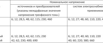
GOST 29322-2014 Standard voltages
This standard applies to: - AC electrical systems with a rated voltage of more than 100 V and a standard frequency of 50 Hz or 60 Hz, used for the transmission, distribution and consumption of electricity, and electrical equipment used in such systems; - AC and DC traction systems; - AC electrical equipment with a rated voltage of less than 120 V and a frequency (usually, but not only) 50 or 60 Hz, DC electrical equipment with a rated voltage of less than 750 V. Such equipment includes batteries (from cells or accumulators), other sources AC or DC power supplies, electrical equipment (including industrial and communications) and household electrical appliances.
GOST R 55630-2013 Pulse overvoltages and overvoltage protection in low-voltage AC systems. General provisions
This standard provides a general overview of the various types of surge voltages that can occur in low-voltage electrical installations, giving typical surge voltages in magnitude and duration, as well as the frequency of their occurrence. The standard contains information on overvoltages associated with the mutual influence of power supply systems and communication systems, provides general guidelines for the selection of means of protection against overvoltages and the construction of a power supply system, taking into account ensuring its efficiency and reliability, including issues of interaction and coordination of protective devices during temporary overvoltages .
GOST R 51992-2011 Low-voltage surge protection devices. Part 1. Surge protection devices in low-voltage power distribution systems. Technical requirements and test methods
This standard applies to devices for protecting electrical networks and electrical equipment under direct or indirect influence of lightning or other transient overvoltages. These devices are intended for connection to AC power circuits with a frequency of 50-60 Hz or DC and to equipment with a rated voltage of up to 1000 V rms or 1500 V DC. Performance characteristics, standard test methods, and ratings are established for such devices that contain at least one nonlinear element designed to limit overvoltages and dissipate surge currents.
GOST R 50571.5.53-2013 Low-voltage electrical installations. Part 5-53. Selection and installation of electrical equipment. Separation, switching and control
This standard applies to low-voltage electrical installations and specifies general requirements for separation, switching and control functions, as well as requirements for the selection and installation of devices provided to perform these functions.
GOST R 50571-4-44-2011 Low-voltage electrical installations. Part 4-44. Security requirements. Protection against voltage fluctuations and electromagnetic interference. P.443 Protection against atmospheric or switching overvoltages 443.1 General requirements.
This section establishes requirements for the protection of electrical installations from transient overvoltages of atmospheric origin transmitted by the power distribution system and from switching overvoltages.
GOST R 50571.7.712-2013 Low-voltage electrical installations. Part 7-712. Requirements for special electrical installations or their locations. Power systems using solar photovoltaics (PV)
This standard applies to electrical installations using solar photovoltaic (PV) power systems, including systems with AC modules.
GOST R 51317.4.5-99 Electromagnetic compatibility of technical equipment. Resistance to high-energy microsecond pulse noise. Requirements and test methods
This standard applies to electrical, electronic and radio-electronic products and equipment (hereinafter referred to as technical means) and establishes requirements and test methods for technical means (TS) for resistance to the effects of high-energy microsecond impulse interference (HIP) caused by overvoltages resulting from switching transients and lightning discharges. Severity levels of HF immunity tests are determined for various electromagnetic and operating conditions.
GOST R 54418.24-2013 Renewable energy. Wind power. Wind power installations. Part 24. Lightning protection
This standard applies to lightning protection of wind power plants (WPPs) and power supply systems of WPPs.
GOST IEC13 Low-voltage surge protection devices. Part 11: Surge protection devices connected to low-voltage power distribution systems. Requirements and test methods
This standard applies to devices for protecting electrical networks and electrical equipment under direct or indirect exposure to lightning or other transient overvoltages. These devices are intended for connection to AC power circuits with a frequency of 50/60 Hz and to equipment with a rated voltage of up to 1000 V rms. Performance characteristics, standard test methods, and ratings are established for such devices that contain at least one nonlinear element designed to limit overvoltages and dissipate surge currents.
GOST R IEC11 Low-voltage surge protection devices. Part 12. Surge protection devices in low-voltage power distribution systems. Principles of selection and application
This standard provides information for the assessment, with reference to IEC 61024-1, IEC 61662 and IEC 60364, of the need for SPDs in low-voltage systems, selection and coordination of SPDs taking into account all the environmental conditions in which they will be used. Examples of these conditions are: protected equipment and system characteristics, insulation level, overvoltages, installation method, SPD placement, SPD coordination, SPD failure mode and consequences of equipment failure.
GOST IEC14 Low-voltage surge protection devices. Part 21: Surge protection devices connected to telecommunications and signaling networks. Performance requirements and test methods
This standard applies to devices for protecting telecommunications and signaling networks from direct or indirect exposure to lightning or other transient overvoltages. The purpose of these SPDs is to protect modern electronic equipment in telecommunications and signaling networks with rated system voltages up to 1000 V AC and 1500 V DC.
GOST R IEC 62305-1-2010 Risk management. Lightning protection. Part 1. General principles
This standard establishes the general principles of lightning protection of buildings, structures and their parts, including people in them, utility networks related to the building (structure), and other objects.
GOST R IEC 62305-2-2010 Risk management. Lightning protection. Part 2: Risk assessment
This standard applies to the assessment of the risk of lightning strikes and their consequences for buildings, structures and their parts. This standard establishes procedures for assessing the risk of lightning strikes for buildings (structures). If an acceptable risk has been established, this procedure allows the selection of appropriate lightning protection measures to reduce the risk to an acceptable value.
GOST R IEC 62305-4-2016 Lightning protection. Part 4. Protection of electrical and electronic systems inside buildings and structures
This standard provides information for the design, installation, inspection, maintenance, and testing of lightning electromagnetic impulse (SPM) protection measures designed to reduce the risk of damage to electrical and electronic systems within a building by lightning electromagnetic events (LEMP).
GOST R 50571.22-2000 Electrical installations of buildings. Part 7. Requirements for special electrical installations. Section 707: Grounding of Information Processing Equipment
This standard applies to electrical installations of buildings used in all sectors of the country's economy, regardless of their affiliation and form of ownership, and establishes requirements for special electrical installations, in particular for the grounding of electrical installations containing information processing equipment.
GOST R IEC 62561.3-2014 Components of lightning protection systems. Part 3. Requirements for isolating spark gaps
This standard establishes requirements for the design and testing of isolating spark gaps in lightning protection systems. Isolating spark gaps can be used for indirect connection of lightning protection system components with other nearby parts and metal structures of structures, when direct connection is not allowed for functional reasons. This standard establishes requirements for the design and testing of isolating spark gaps in lightning protection systems. Isolating spark gaps can be used for indirect connection of lightning protection system components with other nearby parts and metal structures of structures, when direct connection is not allowed for functional reasons.
GOST R 55212-2012/IEC/TR 60664-2-2:2002 Insulation coordination for equipment in low-voltage systems. Part 2-2. Consideration of issues related to the interface. Application Guide
This standard provides an overview of the different types of breakdown overvoltages that can occur in low voltage installations and equipment, and in particular addresses: - the magnitude and duration of a typical breakdown that is a random event; — information on overvoltages resulting from the interaction between the power supply system and the systems connected to it; — general guidance when taking into account the output interface depending on the coordination of the insulation; — general guidance regarding surge protection intended for public areas and the risks considered, including interactions in the system; — temporary lightning overvoltages and other factors that are considered in connection with the coordination of insulation, primarily related to the control of protection through the use of surge protection equipment.
GOST R 53735.5-2009 Valve arresters and nonlinear surge suppressors for alternating current electrical installations for voltages from 3 to 750 kV. Part 5. Recommendations for selection and use
This standard applies to valve arresters (hereinafter referred to as VR) and nonlinear surge arresters (hereinafter referred to as surge suppressors) and establishes a methodology for their selection and application to limit lightning and switching overvoltages on AC electrical equipment with voltages from 3 to 750 kV.
GOST 32144-2013 Electrical energy. Electromagnetic compatibility of technical equipment. Standards for the quality of electrical energy in general-purpose power supply systems
This standard establishes indicators and standards for the quality of electrical energy (EQ) at the points of transmission of electrical energy to users of low, medium and high voltage electrical networks of general purpose AC power supply systems with a frequency of 50 Hz.
GOST R IEC 60269-1-2010 Low-voltage fuses. Part 1. General requirements
This standard applies to fuses equipped with current-limiting closed fuse-links with a rated breaking capacity of not less than 6 kA, designed to protect industrial frequency alternating current circuits with a rated voltage not exceeding 1000 V or direct current circuits with a rated voltage not exceeding 1500 V.
Organization standards
STO Gazprom 2-1.11-170-2007 Instructions for the installation of lightning protection of buildings, structures and communications of OJSC Gazprom
STO 56947007-29.130.15.114-2012 Guidelines for the design of grounding devices for 6-750 kV substations
STO 56947007-29.240.02.001-2008 Guidelines for the protection of electrical networks with a voltage of 0.4-10 kV from lightning overvoltages
STO 56947007-29.130.15.105-2011