The theory of calculating electrical loads, the foundations of which were formed in the 1930s, aimed to determine a set of formulas that provide an unambiguous solution for given electrical receivers and graphs (indicators) of electrical loads. In general, practice has shown the limitations of the “bottom-up” approach, based on initial data on individual electrical receivers and their groups. This theory remains important when calculating the operating modes of a small number of electrical receivers with known data, when adding up a limited number of graphs, and when calculating for 2UR.
In the 1980s–1990s. The theory of calculating electrical loads increasingly adheres to non-formalized methods, in particular, the complex method of calculating electrical loads, elements of which were included in the “Guidelines for calculating electrical loads of power supply systems” (RTM 36.18.32.0289). Probably, working with information databases on electrical and technological indicators, cluster analysis and pattern recognition theory, constructing probabilistic and cenological distributions for expert and professional assessment can finally solve the problem of calculating electrical loads at all levels of the power supply system and at all stages of making a technical or investment decision .
The formalization of calculation of electrical loads has developed over the years in several directions and led to the following methods:
- empirical (method of demand coefficient, two-term empirical expressions, specific electricity consumption and specific load densities, process schedule);
- ordered diagrams, transformed into calculations based on the calculated active power factor;
- actually statistical;
- probabilistic modeling of load diagrams.
Demand Coefficient Method
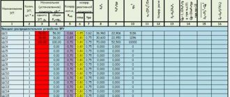
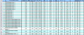
The demand coefficient method is the simplest, most widespread, and is where load calculations began. It consists of using expression (2.20): based on the known (specified) value of Ru and the tabulated values given in the reference literature (for examples, see Table 2.1):
The value of Kc is assumed to be the same for electrical receivers of the same group (operating in the same mode), regardless of the number and power of individual receivers. The physical meaning is a fraction of the sum of the rated powers of electrical receivers, statistically reflecting the maximum practically expected and encountered mode of simultaneous operation and loading of some indefinite combination (implementation) of installed receivers.
The reference data provided for Kc and Kp correspond to the maximum value, and not the mathematical expectation. Summing the maximum values rather than the average inevitably inflates the load. If we consider any group of electrical power supply systems of the modern electrical economy (and not those of the 1930s-1960s), then the conventionality of the concept of “homogeneous group” becomes obvious. Differences in the value of the coefficient - 1:10 (up to 1:100 and higher) - are inevitable and are explained by the cenological properties of the electrical economy.
In table Table 2.2 shows the LGS values characterizing the pumps as a group. When deepening the research on KQ4, for example only for raw water pumps, there may also be a spread of 1:10.
It is more correct to learn to evaluate Cs as a whole for the consumer (section, department, workshop). It is useful to carry out an analysis of calculated and actual values for all similar technology objects of the same level of the power supply system, similar to Table. 1.2 and 1.3. This will allow you to create a personal information bank and ensure the accuracy of calculations. The method of specific electricity consumption is applicable for sections (installations) of 2UR (second, third... Level of the Power System), departments of missile defense systems and workshops of 4UR, where the technological products are homogeneous and change little quantitatively (an increase in output, as a rule, reduces the specific electricity consumption Ay).
Calculation of electrical loads
Today we will talk about how to correctly calculate the electrical power consumption for a private home, what the installed and calculated load power is, and why all these calculations are needed in general.
Electrical loads are calculated for two main reasons.
First, having an idea of how much dedicated power your home needs, you can contact your energy sales company to get exactly the power you need. True, we need to take into account our realities; they will not always meet you. In rural areas, power grids are often in a very poor condition and there is a strict limit on the allocated electricity, so in the best case you will be allocated no more than 15 kW, and sometimes even this cannot be achieved.
Secondly, the calculated power of all consumers is the main indicator when choosing the rated currents of protective and switching devices, as well as when choosing the required cross-section of conductors.
So, after calculating the electrical loads of all our consumers, we will find out the total calculated power (calculated current). This concept means power equal to the expected maximum network load in 30 minutes.
In order to correctly perform the calculation, we need to know the installed power of all electrical receivers and the calculated coefficients.
Installed power is the sum of the rated powers of all electricity consuming devices in the house. The rated power value is taken from the passport data for electrical equipment and is not the actual power consumption.
The design coefficients that must be taken into account in the calculations are the demand coefficient Ks, the utilization coefficient Ki and the power coefficient cos φ.
The demand factor is the ratio of the combined half-hour maximum load of electrical receivers to their total installed capacity. That is, it is introduced taking into account the fact that at any given time not all electrical appliances will consume their full power.
Ks = Рр/Ру ,
where Рр – calculated electrical load, kW; Ru – installed power of electrical receivers, kW.
Utilization factor is the ratio of actual power consumption to installed power over a certain period of time.
Ki = P/Ru
Power factor cosφ is the ratio of the active power consumed by the load to its total power.
cosφ = Р/S
where P – active power, kW; Ru – total power, kVA.
All coefficients are taken from the tables of the relevant regulatory documents. The table below also shows the nameplate (nominal) power of individual electrical consumers.
| Name | Rated power kW | Estimated odds | |
| demand Ks | using Ki | ||
| Washing machine | 2 | 1,0 | 0,6 |
| Dishwasher | 2 | 0,8 | 0,8 |
| Instantaneous water heater | 3,5 | 0,4 | 1,0 |
| Air conditioner | 2,5 | 0,7 | 0,8 |
| Electric fireplace | 2 | 0,4 | 1,0 |
| Boiler | 6 | 0.6 | 0,9 |
| Electric heater | 2 | 0,8 | 1,0 |
| Fan heater | 1,5 | 0,9 | 0,9 |
| Warm floor | 60 W/m2 | 0,5 | 1,0 |
| Food processors, coffee makers, electric kettles (total) | 4-5 kW | 0,3 | 1,0 |
| Sauna | 4-12 kW | 0,8 | 0,8 |
| Shower cabin | 3,0 | 0,6 | 0,8 |
| Lawnmower | 1,5 | 0,4 | 0,8 |
| Submersible pump | 0.75 – 1.5 kW | 0,8 | 0,9 |
| Computers | 0,5 | 0,6 | 1,0 |
| Household electrical outlet (TV, refrigerator, iron, vacuum cleaner, etc.) | 100 W/socket | — | 0,7 — 1,0 |
| Kitchen lighting | 25-30 W/m2 | 1,0 | 0,8 |
| Corridor lighting | 20-25 W/m2 | 0,8 | 0,8 |
| Living room lighting | 35-40 W/m2 | 0,8 | 0,8 |
| Bedroom lighting | 25-30 W/m2 | 1,0 | 0,8 |
For example, let's assume that we have a country house with two rooms, a kitchen and a hallway. The power supply at home is single phase. For further calculations, we will draw up a table with all the electrical consumers in the house.
| Room | Consumers | Rated power kW |
| Kitchen | Lighting 2 Sockets Washing machine Refrigerator | 0,1 0,2 2,2 0,7 |
| Room | Lighting 3 Sockets Electric heater Computer | 0,2 0,3 2 0,5 |
| Room | Lighting 2 Outlets Fan | 0,1 0,2 0,3 |
| Hallway | Lighting 2 Sockets | 0,1 0,3 |
Next, we proceed directly to calculating the power, taking into account all the coefficients. We will combine all similar electrical receivers, such as electrical outlets and lighting, into groups and add up their rated power. We will count the remaining receivers separately.
| Consumers | Rated power kW | Estimated odds | Design power | Rated current | |||
| Demand | Uses | Power | Active kW | Full kVA | |||
| Lighting | 0,5 | 0,7 | 0,8 | 1 | 0,28 | 0,28 | 1,3 |
| Sockets | 1 | 0,3 | 0,8 | 0,8 | 0,24 | 0,3 | 1,4 |
| Washing machine | 2,2 | 1 | 0,6 | 0,75 | 1,32 | 1,76 | 8 |
| Fridge | 0,7 | — | 0,8 | 0,65 | 0,56 | 0,9 | 4 |
| Electric heater | 2 | 0,8 | 1 | 1 | 1,6 | 1,6 | 7,3 |
| Computer | 0,5 | 0,6 | 1 | 0,65 | 0,3 | 0,5 | 2,3 |
| Fan | 0,3 | — | 1 | 0,75 | 0,3 | 0,4 | 1,9 |
| 7,2 | 4,6 | 5,74 | 26,2 | ||||
To determine the estimated active power, it is necessary to multiply the rated (installed) power by the demand and use coefficients - Pр = Pу * Ks * Ki .
We find the total power by dividing the calculated active power by the power factor - S = Pp/cos φ .
The rated current for a single-phase network is determined by the formula Ip = Pp/U*cos φ or Ip = S/U . For a three-phase network, the formula will look like this : Ip = Pp/1.73*U*cos φ or Ip = S/1.73*U .
In order to roughly estimate how much power is needed for a home, you don’t have to make such detailed calculations. It is enough to add up the installed capacity of consumers that will be used and multiply this value by the demand coefficient.
| Rated power kW | up to 14 | 20 | 30 | 40 | 50 | 60 | 70 or more |
| Demand factor | 0,8 | 0,65 | 0,6 | 0,55 | 0,5 | 0,48 | 0,45 |
However, we must take into account that this value will be very approximate and will have to be adjusted in the future.
Share on social media networks
Maximum power method
In real conditions, prolonged operation of a consumer does not mean a constant load at the point of its connection at a higher level of the power supply system. As a statistical value Lud, determined for some previously identified object by power consumption A and volume L/, there is some averaging over a known, usually monthly or annual, interval. Therefore, the application of formula (2.30) gives not the maximum, but the average load. To select SAM transformers, you can take Psr = Pmax. In the general case, especially for 4UR (shop), it is necessary to take into account Kmax as T and take the actual annual (daily) number of operating hours of production with maximum use of active power.
Table.2.4
| № | Workshop name | Rn | cosj tgj | KS | RR | Or |
In table 2.4 it is advisable to highlight the calculated load of electric power supply voltages above 1000 V (6-10 kV) as a separate section. In addition, it should be remembered that among electric motors with voltages above 1000 V, synchronous electric motors are often used, which (to unify calculations) are taken with cosj = 0.9 - “leading”, i.e., delivering reactive energy to the network. Therefore, their calculated reactive power is taken with a minus sign (it will be subtracted in the algebraic sum).
When determining the design power of a plant, it is also necessary to take into account power losses in workshop transformers and the lighting load.
Since at this stage the power of workshop transformer stations is not known, the power losses in these transformers are taken into account approximately based on the total values of loads in the workshop with voltages up to 1000 V, that is
;
;
;
;
When calculating the lighting load of a workshop (factory), the demand coefficient method is used. In this case, it is assumed that power electrical equipment and lighting will be connected to the same transformers of workshop transformer substations. In this case, the estimated power of the lighting load will be determined by the formulas
Po = F × s × Kco;
Qо = Po × tgjо,
where F is the area of the workshop (factory territory), m2; s—specific density of lighting load, W/m2; Kco is the demand coefficient of the lighting load.
Note:
it is necessary to take into account that incandescent lamps have cosj = 1, fluorescent and gas-discharge lamps –
cosj = 0.9. When calculating the power of the lighting load, the lighting of the enterprise territory cannot be neglected.
The calculated maximum workshop voltage of 0.4 kV, taking into account the lighting load and losses in the transformer, is determined by the formulas
Рм = Р`м + Ро + DРm;
Qm =Q`S + Qо + DQm;
It is advisable to present the calculation results in the form of a table. 2.5, while power receivers for 0.4 kV and electric power supply for 6 - 10 kV must be separated into separate sections. The design capacity of the enterprise as a whole, taking into account the coefficient of different times of maximums, is determined by the following expressions:
Рз = (Рм 0.4 + Рм 6 – 11) × Kr. m;
Qз = (Qm 0.4 + Qm 6 – 11) × Kr. m;
Table.2.5
| № | Workshop name | R'm | Q'm | Qb | Q`SM | F, m2 | s, W/m2 | XO | Ro | Qо | DРм | DQm | Rm | Qm | Sm |
| 1 | |||||||||||||||
| 2 | |||||||||||||||
| 3 |
Depending on the number of connections and the group utilization coefficient Ki according to the table. 2.6 determines the value of the coefficient of different times of maxima Kr. m. When calculating the electrical load at different voltage levels, the group utilization coefficient is taken to be equal to the group demand coefficient, which is found as the arithmetic mean of the coefficient for all electric power supply units. The multi-temporal maximum coefficient is the ratio of the calculated power on 6-10 kV buses to the sum of the calculated powers of consumers connected to the 6-10 kV buses of the RP, GPP.
Method of specific load densities
The method of specific load densities is close to the previous one. The specific power (load density) y is set and the area of the building or site, department, workshop is determined (for example, for mechanical engineering and metalworking shops y = 0.12...0.25 kW/m2; for oxygen converter shops y = = 0.16... 0.32 kW/m2). A load exceeding 0.4 kW/m2 is possible for some areas, in particular for those where there are single power receivers with a unit power of 1.0...30.0 MW.
Process schedule method
The process schedule method is based on the operating schedule of a unit, line or group of machines. For example, the operating schedule of an arc steel-smelting furnace is specified: the melting time (27...50 min), oxidation time (20...80 min), the number of heats, and technological linkage with the operation of other steel-smelting units are indicated. The graph allows you to determine the total energy consumption per melt, the average per cycle (taking into account the time before the start of the next melt), and the maximum load for calculating the supply network.
