Electrical energy source - an electrical product (device) that converts various types of energy into electrical energy for power plants.
The fuel for power plants is natural resources - coal, peat, water, wind, sun, nuclear energy, etc.
Depending on the type of energy being converted, power plants can be divided into the following main types: thermal, nuclear, hydroelectric power plants, pumped storage, gas turbine, as well as low-power local power stations - wind, solar, geothermal, tidal, diesel, etc.
- A thermal power plant (TPP) converts heat energy into electricity. Thermal power plants operate on fossil fuels - fuel oil, coal, peat, gas, shale (Fig. 1)
- A hydroelectric power plant (HPP) converts the energy of water movement into electricity. Hydroelectric power plants are built in places where large rivers are blocked by a dam, and using the energy of falling water, they rotate the turbines of an electric generator. There are dam and diversion types of hydroelectric power stations.
- Nuclear power plants (NPPs) differ from a conventional steam turbine station in that nuclear power plants use the fission process of uranium, plutonium, thorium, etc. nuclei as an energy source (Fig. 1).
Figure 1 - Power plants: a-thermal (TPP); b-dam hydroelectric power station; v-atomic
Non-traditional energy sources will become the main ones by 2050, scientists say, and traditional ones will lose their need.
- Solar energy (Fig. 2) is widely used for both heating water and generating electricity. Solar collectors are made from available materials: steel, copper, aluminum, etc., that is, without the use of scarce and expensive silicon. This allows you to significantly reduce the cost of equipment and the energy produced by it. Currently, solar water heating is the most effective way to convert solar energy.
- A wind power plant (WPP) (Fig. 2) converts wind energy into electrical energy.
- Tidal power plants are based on the use (Fig. 2.) of tidal energy.
- Unconventional geothermal energy sources (Fig. 2) are based on the use of heat from earth turbines (deep hot springs).
- Biochemical power plant (Fig. 2). New promising energy sources – biomass.
Figure 2 - Non-traditional energy sources: a – solar panels; wind power plant; tidal power station; geothermal power plant; d-biochemical power plant using biomass
According to the rules for the construction of electrical installations (PUE), there are three categories that differ in the degree of reliability and protection of electrical receivers.
The first category implies a continuous supply of electricity to objects and does not allow interruptions in power supply. Interruptions in the supply of current can lead to very serious consequences, namely:
- threat to human life and health;
- significant financial losses;
- breakdown of expensive equipment, violation
- functioning of housing and communal services facilities;
- failure in technological processes, etc.
Electric receivers of the first category are widely used in industry (chemical, metallurgical), mines, medical institutions and intensive care units, boiler rooms, fire-fighting devices, elevators, etc.
The second category of electrical receivers includes devices, the disconnection of which can lead to the following consequences:
- disruption of the production cycle and under-supply of products;
- downtime of equipment, transport and various mechanisms;
- disrupting the life of entire areas and large numbers of people.
The second category of power supply to electrical receivers includes residential multi-apartment buildings, dormitories, children's and medical institutions, sports facilities, shops, catering establishments, schools, museums, bathhouses, etc.
The third reliability category includes installations that cannot be classified into the first two groups. These can be residential apartment buildings, small production sites and auxiliary workshops. Power is supplied from a single source, and interruptions in energy supply can reach up to 24 hours (72 hours per year).
II. Electricity production and use
Electricity generation
Electricity generation is the production of electricity by converting it from other types of energy using special technical devices. To generate electricity, use: Electric generator - an electrical machine in which mechanical work is converted into electrical energy. A solar battery or photocell is an electronic device that converts the energy of electromagnetic radiation, mainly in the light range, into electrical energy. Chemical current sources are the conversion of part of chemical energy into electrical energy through a chemical reaction. Radioisotope sources of electricity are devices that use the energy released during radioactive decay to heat a coolant or convert it into electricity. Electricity is generated at power plants: thermal, hydraulic, nuclear, solar, geothermal, wind and others. Almost all power plants of industrial importance use the following scheme: the energy of the primary energy carrier, using a special device, is first converted into mechanical energy of rotational motion, which is transferred to a special electrical machine - a generator, where electric current is generated. The main three types of power plants: thermal power plants, hydroelectric power plants, nuclear power plants. Thermal power plants (TPPs) play a leading role in the electric power industry of many countries. Thermal power plants require huge amounts of organic fuel, but its reserves are decreasing, and the cost is constantly increasing due to increasingly complex production conditions and transportation distances. Their fuel utilization rate is quite low (no more than 40%), and the volume of waste that pollutes the environment is large. Economic, technical, economic and environmental factors do not allow thermal power plants to be considered a promising way to generate electricity. Hydroelectric power plants (HPP) are the most economical. Their efficiency reaches 93%, and the cost of one kWh is 5 times cheaper than other methods of generating electricity. They use an inexhaustible source of energy, are serviced by a minimum number of workers, and are well regulated. In terms of the size and power of individual hydroelectric power stations and units, our country occupies a leading position in the world. But the pace of development is hampered by significant costs and construction time due to the remoteness of hydroelectric power station construction sites from large cities, lack of roads, difficult construction conditions, subject to the influence of seasonality of river regimes, large areas of valuable riverine lands are flooded by reservoirs, large reservoirs negatively impact the environmental situation, powerful hydroelectric power stations can only be built in places where appropriate resources are available. Nuclear power plants (NPPs) operate on the same principle as thermal power plants, i.e., the thermal energy of steam is converted into mechanical energy of rotation of the turbine shaft, which drives the generator, where mechanical energy is converted into electrical energy. The main advantage of nuclear power plants is the small amount of fuel used (1 kg of enriched uranium replaces 2.5 thousand tons of coal), as a result of which nuclear power plants can be built in any energy-deficient areas. In addition, the reserves of uranium on Earth exceed the reserves of traditional mineral fuel, and during trouble-free operation of nuclear power plants they have little impact on the environment. The main disadvantage of nuclear power plants is the possibility of accidents with catastrophic consequences, the prevention of which requires serious safety measures. In addition, nuclear power plants are poorly regulated (it takes several weeks to completely shut them down or start them up), and technologies for processing radioactive waste have not been developed. Nuclear energy has grown into one of the leading sectors of the national economy and continues to develop rapidly, ensuring safety and environmental cleanliness.
1.1 Generator
An electric generator is a device in which non-electrical types of energy (mechanical, chemical, thermal) are converted into electrical energy. The principle of operation of the generator is based on the phenomenon of electromagnetic induction, when an EMF is induced in a conductor moving in a magnetic field and crossing its magnetic lines of force. Therefore, such a conductor can be considered by us as a source of electrical energy. The method of obtaining induced EMF, in which the conductor moves in a magnetic field, moving up or down, is very inconvenient for practical use. Therefore, generators use not linear, but rotational movement of the conductor. The main parts of any generator are: a system of magnets or, most often, electromagnets that create a magnetic field, and a system of conductors that cross this magnetic field. An alternator is an electrical machine that converts mechanical energy into alternating current electrical energy. Most alternators use a rotating magnetic field.
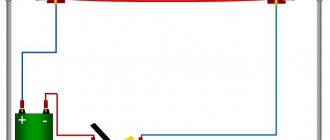
| Alternating current generators, as well as direct current generators, are based on the use of the phenomenon of electromagnetic induction. The DC generator commutator in the AC generator is replaced by slip rings. In the simplest alternating current generator, the conductors, made in the form of a frame, are connected at their ends to slip rings. The rings rotate with the frame; brushes slide along their surface, connecting the generator to the external circuit. In AC electrical machines, the rotating part is called the rotor and the stationary part is called the stator. | A permanent magnet rotates in a rectangular circuit |
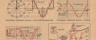
When the frame rotates, the magnetic flux through it changes, so an emf is induced in it. Since the frame is connected to an external electrical circuit using a current collector (rings and brushes), an electric current arises in the frame and the external circuit. With uniform rotation of the frame, the angle of rotation changes according to the law:
The magnetic flux through the frame also changes over time, its dependence is determined by the function:
where S is the area of the frame. According to Faraday's law of electromagnetic induction, the induced emf arising in the frame is equal to:
where is the amplitude of the induced emf. Another quantity that characterizes the generator is the current strength, expressed by the formula:
where i is the current strength at any time, Im is the amplitude of the current strength (the maximum absolute value of the current strength), φc is the phase shift between fluctuations in current and voltage. The electrical voltage at the generator terminals changes according to a sinusoidal or cosine law:
or
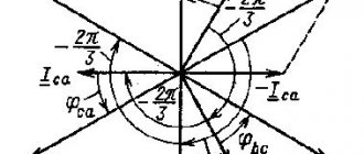
Almost all generators installed in our power plants are three-phase current generators. Essentially, each such generator is a connection in one electric machine of three alternating current generators, designed in such a way that the emfs induced in them are shifted relative to each other by one third of the period:
Electricity usage
Power supply for industrial enterprises. Industrial enterprises consume 30-70% of the electricity generated as part of the electrical power system. The significant variation in industrial consumption is determined by the industrial development and climatic conditions of different countries. Power supply for electrified transport. Rectifier substations of electric transport on direct current (urban, industrial, intercity) and step-down substations of intercity electric transport on alternating current are powered by electricity from the electrical networks of the EPS. Electricity supply for municipal and household consumers. This group of buildings includes a wide range of buildings located in residential areas of cities and towns. These are residential buildings, administrative buildings, educational and scientific institutions, shops, healthcare buildings, cultural buildings, public catering, etc.
Basic technological processes in the electric power industry
Determination of power quality by analyzers
Electricity production in Russia is based on three pillars of the energy system. These are nuclear, thermal and hydropower.
Three types of electricity generation
| Power station | Fuel | Generation |
| TPP | Coal, fuel oil | Obtaining steam from fuel combustion that drives generator turbines |
| hydroelectric power station | Potential energy of water flow | Movement of turbines under water pressure |
| NPP | Uranium cores | Generating steam from the heat of a nuclear reaction. Steam energy drives generator steam turbines |
III. Transformers
Transformer is a static electromagnetic device having two or more inductively coupled windings and designed to convert one (primary) alternating current system into another (secondary) alternating current system by means of electromagnetic induction.
Transformer device diagram
1 – primary winding of the transformer 2 – magnetic circuit 3 – secondary winding of the transformer Ф – direction of magnetic flux U1 – voltage on the primary winding U2 – voltage on the secondary winding
The first transformers with an open magnetic circuit were proposed in 1876 by P.N. Yablochkov, who used them to power an electric “candle”. In 1885, Hungarian scientists M. Dery, O. Blati, K. Tsipernovsky developed single-phase industrial transformers with a closed magnetic circuit. In 1889-1891. M.O. Dolivo-Dobrovolsky proposed a three-phase transformer.
Purpose
Transformers are widely used in various fields: For the transmission and distribution of electrical energy. Typically, in power plants, alternating current generators produce electrical energy at a voltage of 6-24 kV, and it is beneficial to transmit electricity over long distances at much higher voltages (110, 220, 330, 400, 500 , and 750 kV). Therefore, transformers are installed at each power plant to increase the voltage. The distribution of electrical energy between industrial enterprises, populated areas, in cities and rural areas, as well as within industrial enterprises, is carried out via overhead and cable lines, at voltages of 220, 110, 35, 20, 10 and 6 kV. Consequently, transformers must be installed in all distribution nodes, reducing the voltage to 220, 380 and 660 V. To ensure the required circuit for switching on valves in converter devices and matching the voltage at the output and input of the converter (converter transformers). For various technological purposes: welding (welding transformers), power supply for electrothermal installations (electric furnace transformers), etc. For power supply of various circuits of radio equipment, electronic equipment, communication and automation devices, electrical household appliances, for separating electrical circuits of various elements of these devices, for voltage matching etc. To include electrical measuring instruments and some devices (relays, etc.) in high voltage electrical circuits or in circuits through which large currents pass, in order to expand the measurement limits and ensure electrical safety. (instrument transformers)
Classification
Transformer classification:
- By purpose: general power (used in power transmission and distribution lines) and special applications (furnaces, rectifiers, welding, radio transformers).
- By type of cooling: with air (dry transformers) and oil (oil transformers) cooling.
- According to the number of phases on the primary side: single-phase and three-phase.
- According to the shape of the magnetic circuit: rod, armored, toroidal.
- According to the number of windings per phase: two-winding, three-winding, multi-winding (more than three windings).
- According to the winding design: with concentric and alternating (disc) windings.
Device
The simplest transformer (single-phase transformer) is a device consisting of a steel core and two windings.
The principle of the design of a single-phase two-winding transformer The magnetic circuit is the magnetic system of the transformer, through which the main magnetic flux is closed. When an alternating voltage is supplied to the primary winding, an emf of the same frequency is induced in the secondary winding. If you connect some electrical receiver to the secondary winding, then an electric current arises in it and a voltage is established at the secondary terminals of the transformer, which is somewhat less than the EMF and depends to some relatively small extent on the load.
| A) | b) |
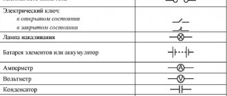
Transformer symbol: a) – transformer with a steel core, b) – transformer with a ferrite core
Transformer characteristics
- The rated power of a transformer is the power for which it is designed.
- Rated primary voltage is the voltage for which the primary winding of the transformer is designed.
- Rated secondary voltage is the voltage at the terminals of the secondary winding, resulting from the no-load condition of the transformer and the rated voltage at the terminals of the primary winding.
- Rated currents are determined by the corresponding rated power and voltage values.
- The highest rated voltage of a transformer is the highest of the rated voltages of the transformer windings.
- The lowest rated voltage is the lowest of the rated voltages of the transformer windings.
- Average rated voltage is a rated voltage that is intermediate between the highest and lowest rated voltage of the transformer windings.
Modes
5.1 Idling
No-load mode is the operating mode of the transformer in which the secondary winding of the transformer is open and alternating voltage is applied to the terminals of the primary winding.
A current flows in the primary winding of the transformer connected to an alternating current source, as a result of which an alternating magnetic flux Φ appears in the core, penetrating both windings. Since Φ is the same in both windings of the transformer, a change in Φ leads to the appearance of the same induced emf in each turn of the primary and secondary windings. The instantaneous value of the induced emf e in any turn of the windings is the same and is determined by the formula:
where is the amplitude of the EMF in one turn. The amplitude of the induced emf in the primary and secondary windings will be proportional to the number of turns in the corresponding winding:
where N1 and N2 are the number of turns in them. The voltage drop across the primary winding, as across a resistor, is very small compared to ε1, and therefore for the effective voltage values in the primary U1 and secondary U2 windings the following expression will be valid:
K – transformation coefficient. When K>1 the transformer is step-down, and when K<1 it is step-up.
5.2 Short circuit mode
Short circuit mode – a mode when the terminals of the secondary winding are closed by a current conductor with a resistance equal to zero (Z=0).
A short circuit of a transformer under operating conditions creates an emergency mode, since the secondary current, and therefore the primary one, increases several tens of times compared to the rated one. Therefore, in circuits with transformers, protection is provided that, in the event of a short circuit, automatically turns off the transformer.
It is necessary to distinguish between two short circuit modes:
Emergency mode - when the secondary winding is closed at the rated primary voltage. With such a short circuit, the currents increase by 15¸ 20 times. The winding is deformed and the insulation becomes charred. Iron also burns. This is hard mode. Maximum and gas protection disconnects the transformer from the network in the event of an emergency short circuit.
The experimental short circuit mode is a mode when the secondary winding is short-circuited, and such a reduced voltage is supplied to the primary winding when the rated current flows through the windings - this is UK - short circuit voltage.
In laboratory conditions, a test short circuit of the transformer can be carried out. In this case, the voltage UK expressed as a percentage, with I1 = I1nom, is designated uK and is called the short-circuit voltage of the transformer:
where U1nom is the rated primary voltage.
This is a characteristic of the transformer indicated in the passport.
5.3 Load mode
Load mode of a transformer is the operating mode of a transformer in the presence of currents in at least two of its main windings, each of which is closed to an external circuit, while currents flowing in two or more windings in no-load mode are not taken into account:
If voltage U1 is connected to the primary winding of the transformer, and the secondary winding is connected to the load, currents I1 and I2 will appear in the windings. These currents will create magnetic fluxes Φ1 and Φ2 directed towards each other. The total magnetic flux in the magnetic circuit decreases. As a result, the emf ε1 and ε2 induced by the total flow decrease. The effective value of voltage U1 remains unchanged. A decrease in ε1 causes an increase in current I1:
As the current I1 increases, the flux Φ1 increases just enough to compensate for the demagnetizing effect of the flux Φ2. Equilibrium is restored again at almost the same value of the total flow.
Nuclear power plants
In nuclear power plants, nuclear energy is converted. The main generator is a reactor, from which heat is released during the fission of nuclei of heavy elements. This is carried out through a chain reaction, as a result of which the generation and then transmission of electricity occurs with its distribution. Compared to traditional thermal power plants, nuclear reactors operate not on fossil fuels, but on nuclear energy obtained from plutonium, uranium and other elements. It is noteworthy that the world's reserves of nuclear resources in the form of the mentioned heavy elements exceed the natural volumes of oil, coal, peat and other fossil fuels. This makes nuclear energy very promising, although from the point of view of environmental safety this ratio can hardly be called favorable.
IV. Electricity transmission
Transferring electricity from power plants to consumers is one of the most important tasks in the energy sector. Electricity is transmitted primarily through overhead AC power lines (OLTs), although there is a trend towards increasing use of cable and DC lines.
The need to transmit electricity over a distance is due to the fact that electricity is generated by large power plants with powerful units, and is consumed by relatively low-power electrical receivers distributed over a large area. The trend towards concentration of generating capacity is explained by the fact that with their growth, the relative costs of constructing power plants decrease and the cost of generated electricity decreases. The placement of powerful power plants is carried out taking into account a number of factors, such as the availability of energy resources, their type, reserves and transportation capabilities, natural conditions, the ability to operate as part of a unified energy system, etc. Often such power plants turn out to be significantly remote from the main centers of electricity consumption. The operation of unified electrical power systems covering vast territories depends on the efficiency of transmitting electricity over distances. It is necessary to transfer electricity from the places of its production to consumers with minimal losses. The main reason for these losses is the conversion of part of the electricity into the internal energy of the wires, their heating.
According to the Joule-Lenz law, the amount of heat Q released during time t in a conductor with resistance R during the passage of current I is equal to:
From the formula it follows that to reduce the heating of the wires it is necessary to reduce the current in them and their resistance. To reduce the resistance of the wires, increase their diameter; however, very thick wires hanging between power line supports can break under the influence of gravity, especially during snowfall. In addition, as the thickness of the wires increases, their cost increases, and they are made of a relatively expensive metal - copper. Therefore, a more effective way to minimize energy losses during electricity transmission is to reduce the current in the wires. Thus, in order to reduce the heating of wires when transmitting electricity over long distances, it is necessary to make the current in them as small as possible. The current power is equal to the current multiplied by the voltage:
Consequently, to maintain the power transmitted over long distances, it is necessary to increase the voltage by the same amount as the current in the wires was reduced:
It follows from the formula that at constant values of transmitted current power and wire resistance, heating losses in the wires are inversely proportional to the square of the network voltage. Therefore, to transmit electricity over distances of several hundred kilometers, high-voltage power lines (power lines) are used, the voltage between the wires of which is tens and sometimes hundreds of thousands of volts. With the help of power lines, neighboring power plants are combined into a single network called a power grid. The Unified Energy System of Russia includes a huge number of power plants controlled from a single center and ensures an uninterrupted supply of electricity to consumers.
V. GOELRO
Story
GOELRO (State Commission for Electrification of Russia) is a body created on February 21, 1920 to develop a project for the electrification of Russia after the October Revolution of 1917.
Over 200 scientists and technicians were involved in the work of the commission. The commission was headed by G.M. Krzhizhanovsky. The Central Committee of the Communist Party and V.I. Lenin personally daily directed the work of the GOELRO commission and determined the main fundamental provisions of the country’s electrification plan.
By the end of 1920, the commission had done a lot of work and prepared the “Electrification Plan of the RSFSR” - a volume of 650 pages of text with maps and diagrams of electrification of areas. The GOELRO plan, designed for 10-15 years, implemented Lenin’s ideas of electrifying the entire country and creating a large industry. In the field of the electric power industry, the plan consisted of a program designed for the restoration and reconstruction of the pre-war electric power industry, the construction of 30 regional power stations, and the construction of powerful regional thermal power plants. The power plants were planned to be equipped with boilers and turbines that were large for that time. One of the main ideas of the plan was the widespread use of the country's enormous hydropower resources. A radical reconstruction based on the electrification of all sectors of the country's national economy and mainly the growth of heavy industry and the rational distribution of industry throughout the country were envisaged. The implementation of the GOELRO plan began in difficult conditions of the Civil War and economic ruin.
Since 1947, the USSR has ranked 1st in Europe and 2nd in the world in electricity production.
The GOELRO plan played a huge role in the life of our country: without it, it would not have been possible to bring the USSR into the ranks of the most industrially developed countries in the world in such a short time. The implementation of this plan shaped the entire domestic economy and still largely determines it.
The drawing up and implementation of the GOELRO plan became possible solely due to a combination of many objective and subjective factors: the considerable industrial and economic potential of pre-revolutionary Russia, the high level of the Russian scientific and technical school, the concentration in one hand of all economic and political power, its strength and will, as well as the traditional conciliar-communal mentality of the people and their obedient and trusting attitude towards the supreme rulers. The GOELRO plan and its implementation proved the high efficiency of the state planning system in conditions of strictly centralized government and predetermined the development of this system for many decades.
results
By the end of 1935, the electrical construction program was exceeded several times.
Instead of 30, 40 regional power plants were built, at which, together with other large industrial stations, 6,914 thousand kW of power were commissioned (of which 4,540 thousand kW were regional - almost three times more than according to the GOELRO plan). In 1935, among the regional power plants there were 13 power plants with 100 thousand kW each.
Before the revolution, the capacity of the largest power plant in Russia (1st Moscow) was only 75 thousand kW; there was not a single large hydroelectric power station. By the beginning of 1935, the total installed capacity of hydroelectric power stations reached almost 700 thousand kW. The largest hydroelectric power station in the world at that time, the Dnieper hydroelectric station, Svirskaya 3rd, Volkhovskaya, etc., were built. At the highest point of its development, the Unified Energy System of the USSR was superior in many respects to the energy systems of developed countries in Europe and America.
Electricity was virtually unknown in villages before the revolution. Large landowners installed small power plants, but their numbers were few.
Electricity began to be used in agriculture: in mills, feed cutters, grain cleaning machines, and sawmills; in industry, and later in everyday life.
List of used literature
Venikov V.A., Long-distance power transmission, M.–L., 1960; Sovalov S. A., Power transmission modes 400–500 sq. EES, M., 1967; Bessonov, L.A. Theoretical foundations of electrical engineering. Electric circuits: textbook / L.A. Bessonov. — 10th ed. - M.: Gardariki, 2002. Electrical engineering: Educational and methodological complex. /AND. M. Kogol, G. P. Dubovitsky, V. N. Borodyanko, V. S. Gun, N. V. Klinachev, V. V. Krymsky, A. Ya. Ergard, V. A. Yakovlev; Edited by N.V. Klinachev. - Chelyabinsk, 2006-2008. Electrical systems, vol. 3 - Energy transmission by alternating and direct current of high voltage, M., 1972. Yavorsky B. M., Detlaf A. A., Handbook of physics for engineers and university students, M.: Nauka, - 2- ed., - 1964, - 848 p. BOSCH car directory. Translation from English First Russian edition. – M.: Behind the Wheel, 2002. – 896 p. Associate Professor of the MCA Department Kuznetsov M.I., Brief lecture notes on the course “Electromechanical systems”. – Perm, 2001. Bogdanov K.Yu., Physics. Grade 11. Textbook. - M.: Education, 2010. - 208 p. Myakishev G.Ya., Bukhovtsev B.B., Sotsky N.N., Physics. Grade 11. Textbook. 19th ed. - M.: Education, 2010. - 399 p. Electrical networks, equipment, documentation, instructions Practical electronics Electrical engineering School for an electrician Physics portal for schoolchildren Brainstorming a transformer Electrical engineering portal for university students and engineers
Sorry, nothing found.
Video
Coffee capsule Nescafe Dolce Gusto Cappuccino, 3 packs of 16 capsules
1305 ₽ More details
Coffee capsules Nescafe Dolce Gusto Cappuccino, 8 servings (16 capsules)
435 ₽ More details
CAM modules