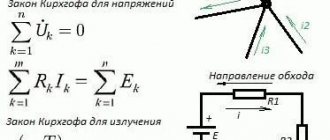
In complex electrical circuits, that is, where there are several different branches and several sources of EMF, a complex distribution of currents also occurs. However, with known values of all the emfs and resistances of the resistive elements in the circuit, we can clear the values of these currents and their direction in any circuit circuit using Kirchhoff's first and second laws . I outlined the essence of Kirchhoff’s laws quite briefly in my textbook on electronics, on the pages of the site https://www.sxemotehnika.ru.
An example of a complex electrical circuit can be seen in Figure 1.
Figure 1. Complex electrical circuit.
Sometimes Kirchhoff's laws are called Kirchhoff's rules , especially in older literature.
So, to begin with, let me remind you of the essence of Kirchhoff’s first and second laws, and then consider examples of calculating currents and voltages in electrical circuits, with practical examples and answers to questions that were asked to me in the comments on the site.
Kirchhoff's first law
Formulation No. 1: The sum of all currents flowing into a node is equal to the sum of all currents flowing out of the node.
Formulation No. 2: The algebraic sum of all currents in a node is equal to zero.
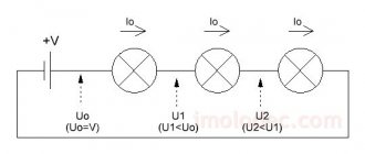
Let me explain Kirchhoff’s first law using the example of Figure 2.
Figure 2. Electrical circuit assembly.
Here the current I1 is the current flowing into the node, and the currents I2 and I3 are the currents flowing out of the node. Then, using formulation No. 1, we can write:
I1 = I2 + I3 (1)
To confirm the validity of formulation No. 2, we transfer the currents I2 and I 3 to the left side of expression (1) , thereby obtaining:
I1 - I2 - I3 = 0 (2)
The minus signs in expression (2) mean that currents flow out of the node.
The signs for inflowing and outflowing currents can be taken arbitrarily, however, in general, inflowing currents are always taken with a “+” sign, and outflowing currents with a “-” sign (for example, as happened in the expression (2)).
You can watch a separate video lesson on Kirchoff's first law in the VIDEO LESSONS section.
On the significance for electrical engineering
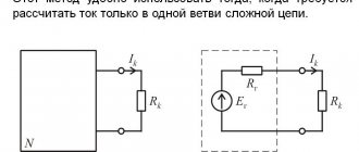
Kirchhoff's rules are of an applied nature and allow, along with and in combination with other techniques and methods (equivalent generator method, superposition principle, method of drawing up a potential diagram) to solve electrical engineering problems. Kirchhoff's rules have found wide application due to the simplicity of the formulation of equations and the possibility of solving them using standard methods of linear algebra (Cramer's method, Gauss's method, etc.).
Kirchhoff's second law.
Formulation: The algebraic sum of the EMF acting in a closed circuit is equal to the algebraic sum of the voltage drops across all resistive elements in this circuit.
Here the term “algebraic sum” means that both the magnitude of the EMF and the magnitude of the voltage drop across the elements can be either with a “+” or a “-” sign. In this case, the sign can be determined using the following algorithm:
1. Select the direction of traversing the contour (two options, either clockwise or counterclockwise).
2. We arbitrarily select the direction of currents through the circuit elements.
3. We arrange signs for the EMF and voltages falling on the elements according to the rules:
— EMF that creates a current in the circuit, the direction of which coincides with the direction of bypassing the circuit, is written with a “+” sign, otherwise the EMF is written with a “-” sign.
— voltages falling across the circuit elements are recorded with a “+” sign if the current flowing through these elements coincides in the direction of bypassing the circuit, otherwise the voltages are recorded with a “-” sign.
For example, consider the circuit shown in Figure 3 and write the expression according to Kirchhoff's second law, going around the circuit clockwise and choosing the direction of the currents through the resistors, as shown in the figure.
Figure 3. Electric circuit to explain Kirchhoff's second law.
E1- E2 = -UR1 - UR2 or E1 = E2 - UR1 - UR2 (3)
I suggest watching a separate video lesson on Kirchoff's second law (theory).
Kirchhoff's rules and laws
Kirchhoff's rules (often called Kirchhoff's Laws in technical literature) are relationships that hold between currents and voltages in sections of any electrical circuit.
Solutions of systems of linear equations compiled on the basis of Kirchhoff's rules make it possible to find all currents and voltages in electrical circuits of direct, alternating and quasi-stationary current.
They are of particular importance in electrical engineering because of their versatility, as they are suitable for solving many problems in the theory of electrical circuits and practical calculations of complex electrical circuits.
Application of Kirchhoff's rules to a linear electrical circuit allows us to obtain a system of linear equations for currents or voltages and, accordingly, when solving this system, find the current values on all branches of the circuit and all internodal voltages.
Formulated by Gustav Kirchhoff in 1845.
The name “Rules” is more correct because these rules are not fundamental laws of nature, but follow from the fundamental laws of conservation of charge and irrotation of the electrostatic field (Maxwell’s third equation with a constant magnetic field). These rules should not be confused with two other Kirchhoff laws in chemistry and physics.
Let's apply Ohm's law in practice
Let's check in practice whether Ohm's law really works. Let's take a battery or accumulator with a voltage of about 9 volts. We need to find out how much current will flow if we close the circuit by connecting a 10 kΩ resistor to it. The circle with the inscription “mA” in the diagram indicates our multimeter (tester) configured to measure amperes.
First we check theoretically. To do this, we use the formulas we know:
U = 9 V, R = 10 kOhm, I =?
I = U / R = 9 V / 10000 Ohm = 0.0009 A = 0.9 mA
This means the tester should show us about 0.9 mA. Now assemble this circuit on a breadboard . In case of problems you can use the example below. Just be careful not to short circuit the circuit when installing components; shorting can damage the battery.
| Don't forget to set your multimeter correctly when measuring current! |
The measurement result in the above circuit is 0.95 mA. Why did we get one figure according to calculations, but in practice, after measuring with a tester, we got another? Please remember that measurements are subject to error. As you remember from the previous article, all resistors have an error of about 5%, as well as the resistance of the probes and the multimeter itself, and besides, the battery or accumulator may not be infected at all 9V! On average, it turns out that the result is correct!
Now, for the test, we need to check what will happen if we connect another resistor, namely 1 kOhm, instead of the 10 kOhm resistor. Keeping Ohm's law in mind, we should already be able to predict that connecting a resistor with 10 times less resistance should produce 10 times more current. Let's check:
Read also: How to turn on the lights automatically?
Potentiometer - tested in practice
Insert the potentiometer into the breadboard and measure the resistance between the center pin and any other pin. After turning the white knob (head) of the potentiometer, the resistance should change.
| Measuring the resistance of the potentiometer before turning the knob. | Measuring the resistance of the potentiometer after turning the knob. |
Now let's check how the potentiometer works , i.e. divides the voltage. Connect battery power to the outermost terminals (legs) of the cell (polarity does not matter), and then measure the voltage between the middle terminal and either extreme terminal. Don't forget to set your multimeter correctly. After some time, turn the white head (knob) of the potentiometer and take the second measurement. The results may look like this:
Read also: What is an ARM processor?
| Measuring voltage on a potentiometer. | Repeated voltage measurement. |
see also
- two node method,
- analysis of sinusoidal current circuits, Ohm's law in complex form,
- two node method,
- Thevenin's theorem,
- Norton's theorem,
- Ohm's law for a section of a circuit, Ohm's law,
Do you like the Kirchhoff method? or do you have any useful tips and additions? Write to other readers below. I hope that now you understand what the Kirchhoff method, Kirchhoff’s law is and why all this is needed, and if you don’t understand, or if you have any comments, then don’t hesitate to write or ask in the comments, I will be happy to answer. In order to gain a deeper understanding, I strongly recommend studying all the information from the category Electrical Engineering, Circuit Engineering, Analog Devices
Write answers to questions for self-test in the comments, we will check, or ask your own question on this topic.
How do voltage regulation integrated circuits work?
Our experiment showed that the power supply voltage depends on the current consumed by the system. If the current draw is relatively high, the battery voltage may drop significantly. So how do power conditioning integrated circuits work to ensure a stable voltage regardless of the load?
In the case of power conditioning integrated circuits , the situation is slightly different: the power regulation circuit built into them constantly compares the voltage at the pins with the voltage requested by the user, and “regulates” it if it is too low. Consequently, the internal resistance of such power supplies can be many times lower than that of even large batteries.
What are potentiometers?
Potentiometers are resistors with an adjustable resistance value. By turning the potentiometer knob, we influence its resistance, measured between the middle and extreme terminals. Examples of potentiometers:
Potentiometers in the diagrams are represented in two ways (the symbol has nothing to do with the type of element):
Depending on the design of the case, the pins or legs may be located differently, but it is always easy to highlight the middle pin, which is the most important:
Potentiometers are very clever voltage dividers: a rotor, made of a highly conductive material, moves across a resistive substance with a constant resistance, dividing it into two resistors. Therefore, the potentiometer circuit looks like this:
Inside, the potentiometer looks something like this - the resistors marked in red are just a symbolic representation of the fact that the rotor divides the resistive substance with constant resistance into two parts (one, outer leg + middle, and the other, outer + middle).
The sum of the resistances of the two resistors obtained in this way is constant, but the value of the resistor to which the voltage is applied changes. The resistance between the extreme terminals is constant, the middle terminal of our resistor is variable resistance.
To facilitate understanding, a modern potentiometer is shown in disassembly :
In addition, the potentiometer can be used as a resistor with adjustable resistance - just use one of the outer terminals and a knob. Now let's test the theory in practice.
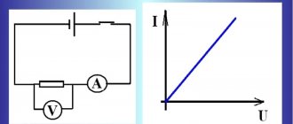
Ohm's law
Current, voltage, and resistance are directly related to Ohm's law, which describes the ratio of voltage (applied to an element) to a given resistance that causes current to flow.
| Remember that we always denote these values as follows: U is voltage, R is resistance, I is current. |
You will encounter this law very often in the field of electronics. Fortunately, you don't need to learn this law by heart, because... In its simplest form, it is expressed by three simple formulas, which for ease of use are usually written in the form of a triangle, as in the picture below:
| In fact, this is one pattern (template), transformed as needed. It is enough to remember one of the formulas (for example, U = I * R) to transform it into another at any time. |
Why do you need a voltage divider?
In the world of electronics, sensors are popular with which the measured physical values are read by measuring the resistance of the sensor, for example, the resistance of an analog temperature sensor depends on the ambient temperature.
Microcontrollers (such as those used in Arduino) cannot measure changes in resistance. However, they are excellent at measuring voltage.
Today, such voltage dividers are not used in electrical circuits. You can certainly use such a divider to power a system that requires 5V from a 9V battery. But you should not use them to power, for example, medium-sized motors (although this sometimes seems like a good idea), since it is impossible to get much power from voltage dividers current! To power such circuits with motors, it is better to use voltage stabilizers, which will be discussed in other articles.
D.C
After reading articles about Kirchhoff’s first and second laws, a dear reader may say: “Okay, MyElectronix, you told me, of course, interesting things, but what should I do next with them? So far, based on your words, I have concluded that if I put together a diagram with my own hands, then I will be able to measure these dependencies in each of its nodes and in each circuit. That's great, but I'd like to calculate patterns rather than just observe dependencies!”
Gentlemen, all these comments are absolutely correct and in response to them we can only talk about the calculation of electrical circuits using Kirchhoff’s laws. Without further ado, let's get straight to the point!
Let's start with the simplest case. It is shown in Figure 1. Let's say the EMF of the power source is E1=5 V, and the resistances R1=100 Ohm, R2=510 Ohm, R3=10 kOhm. It is required to calculate the voltage across the resistors and the current through each resistor.
Gentlemen, I will note right away that this problem can be solved in a much simpler way than using Kirchhoff’s laws. However, now our task is not to look for optimal solutions, but to use a clear example to consider the methodology for applying Kirchhoff’s laws when calculating circuits.
Figure 1 – Simple diagram
In this diagram we can see three circuits. If the question arises – why three, then I recommend looking at the article about Kirchhoff’s second law. In that article there is almost the same diagram with a visual explanation of the method for calculating the number of circuits.
Gentlemen, I want to point out one subtle point. Although there are three circuits, there are only two independent ones. The third circuit includes all the others and cannot be considered independent. And in general, in all calculations we should always use only independent contours. Don't be tempted to write another equation at the expense of this general outline, nothing good will come of it.
So, we will use two independent circuits. To do this, we specify in each contour the direction of traversal of the contour. As we have already said, this is a certain direction in the circuit, which we take as positive. To some extent, we can call this an analogue of coordinate axes in mathematics. We will draw the direction of traversal of each contour with a blue arrow.
Next, let's set the direction of the currents in the branches: we'll just put it at random. It doesn’t matter whether we guess the direction now or not. If you guessed right, then at the end of the calculation we will receive a current with a plus sign, and if we were wrong, with a minus sign. So, let's denote the currents in the branches with black arrows labeled I1, I2, I3.
We see that in circuit No. 1 the direction of the currents I1 and I3, as well as the direction of the power source, coincide with the direction of the bypass, so we will count them with a plus sign. In circuit No. 2, the current I2 will coincide with the direction of the bypass, therefore it will have a plus sign, and the current I3 is directed in the other direction, therefore it will have a minus sign. Let's write Kirchhoff's second law for circuit No. 1:
Now let’s write down the same law for circuit No. 2:
We see that there are no power sources in circuit No. 2, so on the left side (where, according to Kirchhoff’s second law, we have the sum of the emf) we have a zero. So, we have two equations, but we have three unknowns (I1, I2, I3). And we know that to find three unknowns we need a system with three independent equations. Where can I get the third missing equation? And, for example, from Kirchhoff’s first law! According to this law we can write
Gentlemen, now everything is in order, we have three equations and three unknowns and all we have to do is solve this system of equations
Let's substitute specific numbers. All calculations will be carried out in the kosher SI system. I recommend that you always count only in it. Resist the temptation to substitute millimeters, miles, kiloamps, etc. somewhere. There may be some confusion.
The solution to such systems is considered almost in elementary school and, I believe, should not cause difficulties. If anything, there are a bunch of mathematical packages that will do this for you, if you are too lazy to do the calculations yourself. Therefore, we will omit the solution process and immediately present the result
We see that all the currents have a plus sign. This means that we correctly guessed their direction. Yes, that is, the currents in the circuit flow exactly in the direction as we drew the arrows in Figure 1. However, from the conditions of the problem it is necessary to find not only the currents through the resistors, but also the voltage drop across them. How to do it? For example, using Ohm's law, which we have already studied. As we remember, Ohm's law relates current, voltage and resistance. If we know any two of these quantities, we can easily find the third. In this case, we know the resistance and the current that flows through that resistance. Therefore, using this formula
find the voltage across each resistor
Please note, gentlemen, that the voltages across resistors R2 and R3 are equal to each other. This is logical, since they are connected to each other in parallel. However, we will not focus much attention on this for now; we will consider this better another time.
So, gentlemen, we solved this simple problem using Kirchhoff’s two laws and Ohm’s law. But this was a very simple example. Let's try to solve a more complex problem. Take a look at Figure 2.
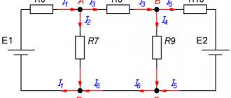
Figure 2 – More complex diagram
The scheme looks impressive, doesn't it? You may not even believe that this scheme can be easily calculated. However, gentlemen, I assure you that you have all the necessary knowledge to calculate this scheme if you have already studied my previous articles. Now you will see this.
To begin with, let's set specific numbers for the values of resistor resistances and source voltages.
Let E1=15 V, E2=24 V, R1= 10 Ohm, R2 = 51 Ohm, R3=100 Ohm, R4=1 kOhm, R5=10 Ohm, R6=18 Ohm, R7=10 kOhm.
Find, as in the previous problem, all currents in the circuit and voltages across all resistors are required.
In this circuit we can see three independent circuits. Let's denote them by Roman numerals I, II, III. In each circuit we will specify the direction of traversal. They are shown with blue arrows.
Next, as last time, we will randomly arrange the directions of the currents in all branches and sign where the current is. It can be seen that in total we have 6 branches and, accordingly, 6 different currents (I1...I6).
Now let's write down Kirchhoff's second law for all three independent circuits.
Kirchhoff's second law for circuit I:
Kirchhoff's second law for circuit II:
Kirchhoff's second law for circuit III:
We have three equations, but there are already 6 unknown currents. As in the previous problem, to obtain the missing equations, we write down the first Kirchhoff laws for nodes.
Kirchhoff's first law for node A:
Kirchhoff's first law for node B:
Kirchhoff's first law for node C:
Actually, we now have a system of 6 equations with 6 unknowns. All that remains is to solve this system
Substituting the numbers specified in the condition, we get
Omitting solutions outside the scope of the article, we present the final result
Gentlemen, we see that almost all currents, except I4, turned out to be with minus signs. This means that we did not guess their direction when we drew the arrows in Figure 2. That is, all currents except current I4 actually flow in opposite directions. And the current I4 flows as we have drawn. At least we guessed correctly with him.
Now, using the same Ohm’s law, exactly as in the previous example, let’s calculate the voltages across the resistors:
That's all, gentlemen: the scheme has been calculated, and the problem has been solved. Thus, you now have a very powerful tool for calculating electrical circuits. Using Kirchhoff's two laws and Ohm's law, you can calculate very complex circuits, find the magnitude of currents and their directions, as well as voltages across all circuit loads. Moreover, knowing the currents and voltages, you can easily calculate the power that is released on these resistors if you use the recommendations from my previous article.
That's all for today, gentlemen. I wish you all great luck and successful settlements!
Join our VKontakte group
Questions and suggestions to the admin: This email address is being protected from spambots. You need JavaScript enabled to view it.
Social button for Joomla