Connecting a conductor to a power source provokes the interaction of charge carriers with the molecular structure of the corresponding substance. Under certain conditions, this process is accompanied by heating. The thermal effect of current is used to create heating elements, fuses, and other devices. Calculation examples and other useful information from this publication will help you solve various practical problems.
A simple experiment demonstrates how the temperature of a conductor increases
Thermal effect of current in solids
This is the very first and most obvious effect of current for us.
The thermal effect of current is manifested in the fact that the medium in which it flows heats up.
For example, we use this action in such everyday appliances as an iron, electric kettle, and coffee maker. In conventional incandescent lamps, the thermal effect of current is also observed (Figure 1).
Figure 1. Thermal effect of current in an incandescent lamp
Such lamps contain a thin tungsten wire, which, when current flows through it, heats up so much that it becomes white-hot. If we raise our hand to such a lamp, we will feel warmth. This is the visual thermal effect of current.
Of course, there is also the fact that this spiral not only gives heat, but also glows. We will talk about the luminous effect of current a little lower.
How can the thermal effect of current be observed experimentally? Let's carry out this experiment to make sure that there is a thermal effect of the current.
Let's connect an iron or nickel wire to the current source, as shown in Figure 2.
Figure 2. Thermal effect of current
After the key is closed, current will appear in the circuit. The wire will become noticeably hot. At the same time, it will lengthen and sag a little. Note that before current was passed through it, it was tightly stretched (in the figure, the original position is indicated by a dotted line).
Thermal effect of current in liquids and gases
The wire in the experiment above was a solid body. Will the thermal effect of current manifest itself in liquids or gases? Will!
To do this, we will conduct the following experiment. Let's take a vessel with ordinary water and lower two metal plates into it (Figure 3). Let's connect them using wires to a current source. Now these plates will be electrodes .
Place a thermometer in the water and record the temperature. We close the key and an electric current flows through the circuit.
Figure 3. Thermal effect of current in liquid
After 10-15 seconds, you will already see that the thermometer has crawled up. The water temperature began to increase.
How can this be explained? An electric field causes electrons to move in a certain direction. Their speed increases. This means that their kinetic energy ($E_к = \frac{m \upsilon^2}{2}$) also increases.
During their movement, these electrons will inevitably collide with other particles of matter (in our case, water). When they collide, they will transfer part of their energy to these particles . This means that when current passes through water, its particles receive some additional energy. The total internal energy of water increases. Do you know that this is exactly what leads to an increase in temperature .
We will not perform an experiment confirming the thermal effect of current in air, due to its great complexity. In general, there are very few phenomena where the thermal effect of current in the air is manifested. But, for example, lightning is a clear natural phenomenon, where the thermal effect of the current is also noticeable.
Can an electric motor be used as a generator?
Content
- Laws allowing the use of an asynchronous electric motor as a generator
- Methods for converting an electric motor into a generator
- Reactive load braking
- Self-excitation of an electric motor
- What you need to know to make an electric motor work as a generator
- How effective is it to use an electric motor as a generator?
Everyone knows that the operation of an electric motor is the conversion of electrical energy into mechanical energy. Will it be possible to get it to convert mechanical energy into electrical energy in order to use the electric motor as a generator? Thanks to the principle of reversibility in electrical engineering, this is possible. But you need to clearly know the operating principle of the unit and create conditions conducive to the transformation.
Laws allowing the use of an asynchronous electric motor as a generator
In a generator, voltage, usually supplied from a battery, excites a magnetic field in the armature winding, and rotation is provided by any physical device. The electric motor does not provide for the possibility of supplying voltage to the armature winding. So that it does not absorb, but produces electricity, a magnetic field must be created artificially.
In an asynchronous motor, the rotating magnetic field of the rotor “lags” behind the stator field, ensuring the process of converting electrical energy into mechanical energy. Therefore, to start the reverse process, you need to make sure that the stator field rotates slower than the rotor field, or that it rotates in the opposite direction.
Methods for converting an electric motor into a generator
There are two ways to “adjust” the stator magnetic field.
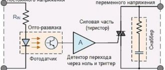
Reactive load braking
This can be done using a powerful capacitor bank. Connect it to the power supply circuit of the engine, which is operating normally. The charge accumulated in the battery will be out of phase with the charge created by the supply voltage, causing the latter to slow down. After this, the motor, instead of absorbing current, begins to generate it, sending it to the network.
Any electric vehicle works precisely thanks to this effect - when moving “independently” downhill, mechanical energy is not required, and the capacitor battery is automatically connected to the power circuit. The generated energy is fed into the network and then converted back into mechanical energy.
Self-excitation of an electric motor
The residual magnetic field of the rotor can produce an emf sufficient to charge the capacitor. As a result, a self-excitation effect occurs, which makes it possible for the engine to switch to electricity generation mode. The continuity of this process is ensured by a capacitor bank, powered by the generated current.
This method is more effective, and it is suitable if you want to use an asynchronous electric motor as a generator.
What you need to know to make an electric motor work as a generator
When converting an engine into a generator, the following technical details should be taken into account:
- Do not attempt to use electrolytic capacitors - they are not suitable for connection in a circuit. You need non-polarized capacitor banks.
- In three-phase machines, capacitors can be connected in a delta or star configuration. In the first case, the output voltage is higher, and in the second, generation begins at lower rotor speeds. Choose the best option to achieve your goal.
- Single-phase squirrel cage induction motors can also generate electricity. Starting is carried out using a phase-shifting capacitor.
Since it is impossible to determine the required capacity of the capacitor bank, it remains to select it by weight - it should be equal to the weight of the engine or slightly exceed it.
How effective is it to use an electric motor as a generator?
Using an electric motor as a generator has its advantages:
- The unit is quite easy to maintain and economical, since the capacitor receives energy from the residual field of the rotor and from the generated current.
- There are practically no “side” wastes of energy on magnetic fields or useless heating.
- The engine, converted into a generator, is sensitive to load changes.
- The frequency of the generated current is often unstable.
- Such a generator cannot provide industrial frequency current.
Chemical effect of current in liquids
How can one experimentally observe the chemical effect of current? Let's return to the previous experiment and take a closer look at the electrodes lowered into water (Figure 4).
Figure 4. Chemical effect of current in water
We will see that even in ordinary water small gas bubbles form around the electrodes. They cannot arise on their own. This means that some kind of chemical reaction is taking place.
Note that we are not talking about boiling here, where we previously observed bubbles forming. The electrodes themselves are barely warm; we can easily touch them with our hands. The temperature of the water is also far from its boiling point. It turns out that the presence of these bubbles is the result of chemical reactions occurring in water when an electric current is passed through it .
Let's conduct another experiment that will more clearly demonstrate to us the chemical effect of current.
Let's replace the water in the vessel from the previous experiment with a solution of copper sulfate $CuSO_4$. It has a blue-greenish color. We will replace metal electrodes with carbon ones (Figure 5).
Figure 5. Chemical effect of current in a solution of copper sulfate
Let's close the key. Current will flow through the circuit. Now let's take a close look at the electrode connected to the negative pole of the current source. A reddish coating has formed on it .
What is this? Where did he come from? This is pure copper $Cu$ . Under the influence of current, it was released from the complex compound and deposited on the negative electrode.
The chemical effect of current is manifested in the fact that when it passes through solutions of salts, acids, and alkalis, a pure substance is released on the electrodes.
This effect of current is actively used in practice in electrometallurgy to obtain pure metals without any impurities (Figure 6).
Figure 6. Detailed illustration of the chemical action of current
This technique is used to apply a thin layer of nickel, silver, and gold to the surface of various objects. This gives the items a beautiful aesthetic appearance and protects them from premature rusting.
Chemical effect of current in solids and gases
In solids, atoms, molecules or ions are tightly bound together. They are located at the nodes of the crystal lattice and are capable of oscillations. The effect of the current is usually not enough to tear them out of their positions. Therefore, they say that usually the chemical effect of current is not observed in solids.
In gases, it is possible to observe such an effect. Remember an electrophore machine, where a spark jumps between the electrodes.
After passing electric sparks through the air, a characteristic odor arises. ozone was discovered (Figure 7). It consists of three oxygen molecules and has strong oxidizing properties. This allows it to be widely used as a disinfectant.
Figure 7. Ozone molecule
Magnetic effect of current
Let's start right away with the experiment. Let's take a copper wire covered with insulating material. Let's wrap it around a nail. We connect the ends of it (the wire) to a current source and a key (Figure 8).
Figure 8. Magnetic effect of current using the example of a nail and copper wire
Let's close the circuit. Let's bring the nail to a pile of small metal objects, for example, other small nails.
What will we see? The nail will attract other iron objects to itself - it has become a magnet. If we open the circuit, the nail will demagnetize.
The most interesting thing is that the magnetic effect of current is universal. It manifests itself in solids, liquids, and gases. In addition, if you force a charge to move directionally in a highly rarefied space (this phenomenon is called current in a vacuum ), then its magnetic effect can be observed here too.
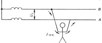
Nature and consequences of human exposure
The nature and consequences of the dangerous and harmful effects of electric current on a person depend on many factors:
- on the magnitude and type (alternating or direct) of the flowing current;
- the duration of its impact (the longer the duration of the current on a person, the more severe the consequences);
- flow paths;
- on the physical and psychological state of a person;
- depending on the state of the external environment, for example, high humidity, the effect of electricity on the body will be stronger.
The magnitude and type of current flow is the main factor on which the outcome of its effect on the human (or animal) body depends.
According to the degree of impact on a person, the current is divided into three threshold values:
- A person begins to feel the impact of alternating current passing through him at a value of 0.6 mA, direct starting from 5-7 mA. These values are called threshold sensible currents.
- The next threshold is the threshold of non-releasing (holding) current. Its value for alternating current is ≥10 mA, for direct current ≥50 mA.
- The third threshold value is fibrillation current. This value of alternating current is 100 mA, and constant current is 300 mA; with a duration of exposure to such current of 0.5 seconds, cardiac arrest or fibrillation may occur.
Table 1 shows the various reactions of the human body to electric current depending on its strength and type.
Table 1 - the effect of electric current on a person depending on the threshold values and type (direct and alternating)
| Current strength, mA | Nature of impact | |
| D.C | AC 50 Hz | |
| 0,6—1,6 | Not felt | The beginning of the sensation is mild itching, tingling of the skin under the electrodes |
| 2—4 | Not felt | The sensation of current spreads to the wrist, slightly cramps the hand |
| 5—7 | The beginning of the sensation. The impression of skin heating under the electrode | The pain intensifies throughout the entire hand and is accompanied by cramps. Hands, as a rule, can be removed from the electrodes |
| 8—10 | Increased feeling of heating | Severe pain and cramps in the entire arm, including the forearm. It is difficult to take your hands off the electrodes |
| 10—15 | Increased feeling of heating | Barely bearable pain in the whole arm. It is impossible to take your hands off the electrodes. |
| 20—25 | An even greater sensation of skin heating. | The hands are instantly paralyzed; it is impossible to tear yourself away from the electrodes. Severe pain, difficulty breathing |
| 25—50 | Feeling of intense heating, pain and cramps in the hands. When you remove your hands from the electrodes, barely bearable pain occurs as a result of convulsive muscle contractions | Very severe pain in the arms and chest. Breathing is extremely difficult. With prolonged current, respiratory paralysis or weakening of heart activity with loss of consciousness may occur |
| 50—80 | A feeling of very strong superficial and internal heating, severe pain in the entire arm and in the chest area. Difficulty breathing. It is impossible to take your hands off the electrodes due to severe pain when contact is broken | Breathing becomes paralyzed within a few seconds, and heart function is disrupted. With prolonged current flow, cardiac fibrillation may occur. |
| 100 | Respiratory paralysis due to prolonged current flow | Heart fibrillation after 2-3 s; after a few more seconds - cardiac paralysis |
| 300 | Heart fibrillation after 2-3 s; after a few more seconds - respiratory paralysis | Same action in less time |
| more than 5000 | Breathing is paralyzed immediately - within a split second. Cardiac fibrillation, as a rule, does not occur; Temporary cardiac arrest is possible during the current flow. If current flows for a long time (several seconds), severe burns and tissue destruction | |
As can be seen from Table 1, alternating current is more dangerous than direct current. However, even a small direct current below the threshold of sensation gives strong shocks that can cause muscle cramps. And at a voltage value above 500 V, direct current is already more dangerous since it has great “stickiness” and it is almost impossible to free yourself from it.
At the same time, although alternating current is considered more dangerous for humans, this mainly concerns the frequency of 50 Hz. With an increase in frequency, even taking into account that the body’s resistance drops and the current flowing through it increases, the danger of electric shock decreases and completely disappears at a frequency of 450 - 500 GHz, because at a high frequency, the so-called “skin” effect occurs - the current flows along the surface of the body, the skin, and cannot affect a person. But we practically never encounter currents of this frequency either in everyday life or in production, in contrast to the 50 Hz alternating voltage, which is the standard in Russian electrical networks.
Return to content
Galvanometer. Magnetic effect of current in its device
First, let's look at how a current-carrying conductor and a magnet will interact.
To do this, we will build the following structure. We attach a thin copper wire to a small frame with several turns. The frame itself will be suspended on threads so that we can observe any of its movements.
The wire that wraps around the frame is connected to the poles of the current source. Let's close the key. The frame will remain motionless (Figure 9).
Figure 9. Frame with current is motionless
Now let's take a magnet. Let's position it so that the current-carrying frame is between its poles (Figure 10).
Figure 10. A current-carrying frame placed between the poles of a magnet rotates
Now the frame has started to turn! It is this phenomenon of interaction of such a peculiar coil with current and a magnet that underlies the design of a special device - a galvanometer (Figure 11).
Figure 11. Galvanometer and its symbols for electrical circuit diagrams
A galvanometer is a device that can be used to determine the presence of current in a conductor.
Figure 11a shows the appearance of this device. Figure 11, b shows the symbol with which a galvanometer is indicated on an electrical circuit diagram.
The galvanometer needle is connected to a coil inside the instrument itself. By coil we mean a wire wound on a dielectric frame.
This coil inside the device is in a magnetic field. When current flows through the coil, the needle deflects. So, when connecting a galvanometer to a circuit, we can judge the presence of electric current in it.
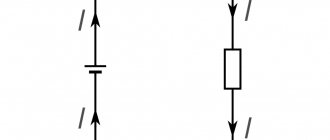
Electric current and Ohm's law
Basic elements of an electrical circuit:
- Current source (generator, galvanic cell, battery, accumulator).
- Current consumers (lamps, heating elements and other electrical appliances).
- Conductors are parts of a circuit that have a sufficient supply of free electrons that can move under the influence of an external electric field. Conductors connect current sources and consumers into a single circuit.
- A key (switch, switch) for closing and opening a circuit.
The electrical circuit may also contain:
- resistor - an element of an electrical circuit that has some resistance;
- rheostat - a device for adjusting the current and voltage in an electrical circuit by obtaining the required resistance value;
- capacitor - a device capable of accumulating electrical charge and transferring it to other elements of the circuit;
- measuring instruments - devices designed to measure the parameters of an electrical circuit.
An electrical diagram is a graphic representation of an electrical circuit in which real elements are presented in the form of symbols.
Light effect of current
Older incandescent bulbs emit more light due to the high temperature of the tungsten wire in their device. Therefore, in their work there is a greater thermal effect of the current.
But in the second half of the 20th century, new light sources were invented. Here the temperature of the conductor itself no longer plays a role, but more complex processes occur.
You probably already guessed that we are talking about LED lamps (Figure 12). At the moment, these are the lamps we most often use in everyday life.
Figure 12. LED lamps
The luminous effect is manifested in the appearance of light radiation during the passage of current.
Tasks
Task No. 1
Consider Figure 8, which shows a setup for observing the magnetic effect of current.
What is each part of this installation? Tell us how the experience goes. At the top of the figure is a current source . wire is connected to its positive terminal . Next, this wire is wound on an ordinary iron nail . The wire runs from the nail to the key , and from the key to the current source (its negative pole).
In the picture the key is closed. Electric current flows in the circuit. An iron nail is instantly magnetized - it becomes a magnet . It attracts other small iron objects to itself.
As soon as we open the circuit, current will stop flowing through the wires. The iron nail will become demagnetized . All small objects previously magnetized to it will disappear.
Task No. 2
Using Figures 9 and 10, tell how the interaction of a frame with current and a magnet is observed experimentally.
Let's assemble an electrical circuit from a current source, a key, connecting wires and a frame with a winding of thin wire connected to the wires . We will hang the frame on threads so that we can track any of its movements.
Let's close the key. Current will flow through the circuit. The frame will remain motionless .
Now let's take a magnet . Let's place it so that the frame is between its poles. Let's close the circuit again. Now the frame began to move - it began to turn .
the magnetic effect of electric current manifests itself . It is this phenomenon that is used in the galvanometer device.
Joule-Lenz law
Electricity is an integral feature of our era. Absolutely everything around is tied to it. Any modern person, even without technical education, knows that electric current flowing through wires can, in some cases, heat them, often to very high temperatures. It would seem that this is known to everyone and is not worth mentioning. However, how to explain this phenomenon? Why and how does the conductor heat up?
Lenz's experiments
Let's fast forward to the 19th century, the era of accumulation of knowledge and preparation for the technological leap of the 20th century. An era when all over the world various scientists and simply self-taught inventors discover something new almost every day, often spending a huge amount of time on research and, at the same time, not presenting the final result.
One of these people, the Russian scientist Emilius Christianovich Lenz, was fascinated by electricity, at the then primitive level, trying to calculate electrical circuits. In 1832, Emilius Lenz was “stuck” with calculations, since the parameters of his simulated circuit “energy source - conductor - energy consumer” varied greatly from experiment to experiment. In the winter of 1832-1833, the scientist discovered that the cause of the instability was a piece of platinum wire that he brought from the cold. When heating or cooling a conductor, Lenz also noticed that there was a certain relationship between the current strength, electrical resistance and temperature of the conductor.