It is customary to classify electrical networks according to the area of application (by purpose), scale characteristics (providing large regions and small current consumers), as well as by the type of current.
By area of application, the following electrical networks are distinguished:
— General purpose (power supply to industrial, household, transport, agricultural consumers. — Autonomous power supply (autonomous and mobile objects: aircraft, vehicles, autonomous stations, ships, spacecraft, etc.). — Technological objects (power supply to engineering networks and production facilities).
A contact network is a special electrical network that serves to transport electricity to vehicles moving along the network (trolleybus, locomotive, tram, metro).
A characteristic feature of the electrical network is that it connects geographically distant points of consumers and sources using power lines.
Electrical energy distribution networks - purpose
Electrical energy distribution systems or distribution networks are designed to
- Delivery of electrical energy with voltage from 6 kV to 10 kV to the consumer.
- Distribution of electrical energy across substations 380 V -35 kV.
- Capacity collection of heating and hydraulic substations with capacities up to hundreds of megawatts.
It is worth noting that in modern conditions, with a constant increase in electricity consumption, it has become conventional to divide electric power transmission and distribution networks by voltage into system-forming ones, transmission systems (extended) and power distribution systems. If previously only networks with voltages up to 35 kV were classified as distribution systems, today individual networks of 110 and even 220 kV can be included in this classification.
That is why, today, electrical energy distribution systems include
- Electrical networks with voltages from 6 to 150 kV, sometimes up to 220 kV.
- Two or three voltage levels after transformation: MV networks - medium voltage 110-150 kV, which are powered by HV (high voltage) networks 330-750 kV. Low voltage (LV) networks from 6 to 35 kV, which are powered from MV networks through MV/LV transformer substations or directly. Through the transformation of VN\NN.
- The lowest voltage level of distribution networks are networks with a voltage of 220-660 V, obtained with additional transformation of 6-35 kV\220-66 kV.
Classification of industrial electrical consumers
Industrial enterprises can be classified according to the following main characteristics:
- according to the total installed (nominal) power of electrical receivers: a) small enterprises - up to 5 mW; b) medium-sized enterprises - 5..75 MW; c) large enterprises - over 75 mW:
- by belonging to the relevant industry (metallurgical, mechanical engineering, petrochemical, etc.);
- according to tariff groups and conditions for determining the power of reactive power compensation means in the electrical networks of an enterprise: a) with an attached transformer capacity of 750 kVA and above - group I; b) with an attached transformer power of less than 750 kVA - group II. Enterprises of the first tariff group pay for the received electricity mainly at a two-rate tariff (for consumed power - the main rate, for consumed electricity - an additional tariff rate). The power of the compensating devices is selected simultaneously with the main elements of the power supply system. Enterprises of tariff group II pay for the electricity received at a single rate tariff. The power of compensating devices that need to be installed in the enterprise's electrical network is indicated by the power system;
- according to the power supply reliability category. With the existing division of power receivers according to power supply reliability requirements into categories I, II and III, a specific enterprise can be assigned to one or another reliability category or categories by assessing the percentage composition of receivers of different categories;
- by energy services category. There are 12 categories of energy services in total. The specific category is determined by the value of the total planned labor intensity of the annual plan for preventive maintenance of energy equipment and networks of the enterprise. It is this value that most objectively reflects the scale and complexity of the energy sector of any enterprise and determines the staffing of the department of the chief energy engineer and its subdivisions.
Most industrial enterprises are located in cities.
Being the main consumers of electricity, cities, depending on the population, are divided into: largest - more than 500 thousand people; large ones - 250-5 00 thousand; large - 100-250 thousand; average - 50-100 thousand; small - up to 50 thousand people.
In turn, the territory of the city is divided into the following zones according to their purpose: 'industrial - for the location of manufacturing enterprises; communal and warehouse - for the placement of transport enterprises (motor depots, trolleybus and tram depots); external transport - for the placement of transport facilities, terminals, ports, stations; residential - for the placement of residential areas, public buildings and structures, places of recreation for the population.
The basis of urban development is made up of civil buildings, which are objects of the non-productive sphere of the national economy: residential buildings, dormitories, hotels, trade and catering enterprises, schools and preschool institutions, consumer services and utilities enterprises, etc.
The location of consumers (power receivers) on the general plan (plan) of an enterprise or city, the size and nature of their electrical loads, the characteristics of power receivers from the point of view of the reliability of supplying them with electricity are the main initial data that determine the choice of the appropriate power supply system.
Distribution network configuration
According to the configuration, distribution networks can be:
- Open (radial and main);
- Closed.
From the diagram we see that the radial circuit is longer and the implementation of the radial circuit requires more conductors, switching equipment, supports, insulators, etc. equipment. As a result, the radial RS circuit is more expensive than the main circuit. But according to the same scheme, we see that if any intermediate section of the backbone network fails, the following sections of the network will be de-energized, which indicates its lower reliability.
Note: In fact, in practice, combined distribution network designs are used, called backup distribution networks.
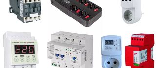
Cable selection and RCD use
To ensure the safety of electrical networks, RCD fire-fighting devices are installed in buildings and certain values are set on the device. In a residential building, the leakage current for common lines is set to 100 mA. Individual lines have a minimum value of 10 mA. When the indicator increases, the residual current device (RCD) de-energizes the building.
Electrical wiring is carried out using safe cables approved by GOST. Aluminum wire is not used for the internal electrical network. It is used to supply electricity to the house. The most preferred option for internal wiring is copper cable. Its advantages include:
- high current density;
- fracture toughness and good wear resistance;
- has little resistance to oxidation;
- Compared to aluminum, it does not compress, so there are no gaps in the joints.
The budget option includes the VVG brand. There are also other types with different properties:
| Cable brand | Purpose |
| Incombustible | Reduced gas and smoke emissions. |
| VVGng with three cores of 6 mm2 each. | For cable ducts in residential buildings. |
| VVGng (3x2.5) | For hidden box on sockets and distribution boxes. |
| VVGng (3x1.5) | Connected to lighting fixtures and switches. |
| PV1 | For electrical panel. |
| PVS (3x2.5) | For electrical appliances. |
For internal stationary wiring, single-core copper wire is most often used, since it is more reliable and durable than its multi-core counterpart.
Cables for internal electrical network
Source: https://yato-tools.ru
Redundant distribution networks
To create a reliable power supply system, medium voltage (MV) distribution networks are made according to backup schemes, simultaneously using both radial and main circuits.
In the figures we see implementations, a radial-backbone diagram of a backup distribution network (Figure 1.3) and a ring closed network diagram with a single power center.
In the next photo we see single and double network configurations with two-way power supply.
And this is a distribution network diagram made in a complex closed configuration with two power supplies (CPU).
Note: CPU is a substation. It receives electrical energy, reduces the high voltage of the distribution network through transformation (step-down substations) and distributes electrical energy to consumers. It is worth noting that there are also step-up substations.
Production
Electricity begins in power plants, which work to convert the mechanical energy of a turbine into electrical energy using a generator (except for solar energy, which uses photovoltaic cells to do this).
Power plants convert energy from fuels such as coal or natural gas, or energy streams such as wind and sunlight. This collection of installations generates a lot of electricity and is often located far from the demand for current.
The following system solves the transmission problem.
Low voltage (LV) distribution networks
Low voltage (LV) distribution networks with a voltage of 380-10000 Volts are the most widespread. Within one network enterprise there may be hundreds of transformer substations and points. This is why such networks use inexpensive transformers without automatic voltage regulation.
©Elesant.ru
Other articles in the section: Electrical networks
- Automatic circuit breakers
- Types of power transmission line supports by material
- Types of supports by purpose
- Overhead power lines with SIP wires
- Wooden supports for overhead power lines
- Reinforced concrete power transmission line supports
- Reinforced concrete power transmission line supports
- Protection of humans from electric shock, direct and indirect contact
- How does a 380 Volt low voltage consumer receive electricity?
- Cable network wells installation stages
Broadcast
Electrical transmission is carried out using lines.
The electricity leaving the power plant passes through special equipment. This system of equipment increases the voltage with a proportional decrease in current (the number of electrons that flow per second). This increase in voltage is carried out by a step-up transformer. This conversion allows current to flow over long distances, with a typical maximum distance of about 500 kilometers.
The reason why step-up transformers are used is that when traveling long distances through a conducting wire, electricity will inevitably lose energy due to resistance in the wires. This problem is essentially solved (not completely, but to an acceptable level) by the use of high-voltage power lines.
The corresponding power losses in the lines with increasing voltage decrease by the square of the current, which means that if the current drops by a factor of 2, the power losses decrease by a factor of 4.
Large high-voltage power lines are an important component of the grid because they transport electricity with little energy loss.
The most modern transmission lines do not use transformers, but are built on powerful semiconductor elements that convert into direct current.
These DC transmission lines are considered more profitable. However, the transition to direct current transmission will require more than a dozen years.