When connecting the phases of electrical receivers in a triangle, each phase will be connected to two linear wires, as shown in the figure below:
Therefore, with this type of connection, back to the star, regardless of the nature and value of the receiver resistance, each phase voltage will be equal to linear, that is, UФ = UЛ. If we do not take into account the resistance of the phase wires, then we can assume that the voltages of the source and receiver of electrical energy are equal.
Based on the above diagram and formula, we can conclude that connecting the phases of electrical energy receivers in a triangle should be used when each phase of a three-phase or two-phase electrical energy consumer is designed for linear network voltage.
Unlike a star connection, where the phase and line currents are equal, with a delta connection they will not be equal. Applying Kirchhoff's first law to nodal points a, b, c, we obtain the relationship between phase and linear currents:
Having the phase current vectors, using this relationship, it is not difficult to construct linear current vectors.
Symmetrical load when connecting receivers in a triangle
For any phase, you can apply formulas that are valid for single-phase circuits:
Obviously, with a symmetrical load:
The vector diagram of phase (linear) voltages and currents with an active-inductive symmetrical load is shown below:
In accordance with formula (1), linear current vectors were constructed. It is also worth paying attention to the fact that when constructing vector diagrams for a triangle connection, the linear voltage vector Uab is usually directed vertically upward.
Line current vectors are often depicted as connecting phase current vectors, as shown in figure b):
Based on this vector diagram, we can write: . The same relationship is true for other phases. Based on this, it is possible to derive a formula for the relationship between phase and linear current for connecting consumer phases with a triangle under a symmetrical load.
Example
The three-phase network has a linear voltage UL = 220 V. It is necessary to connect a three-phase electrical receiver with a phase voltage of 220 V and containing an active rph = 8.65 Ohm and an inductive xph = 5 Ohm resistance connected in series.
Solution
Since the linear and phase voltages in this case will be equal, we choose the method of connecting the consumer windings into a triangle.
Linear and phase currents, as well as phase impedances will be equal:
The active, reactive and apparent power of an electrical receiver of any phase will be equal to:
Vector diagrams are shown above.
Star and triangle connection principle. Features and operation
To increase the transmission power without increasing the network voltage, to reduce voltage ripple in power supplies, to reduce the number of wires when connecting the load to the power supply, various circuits for connecting the windings of power sources and consumers (star and delta) are used.
Scheme
The windings of generators and receivers when working with 3-phase networks can be connected using two circuits: star and triangle. Such circuits have several differences among themselves; they also differ in current load. Therefore, before connecting electrical machines, it is necessary to find out the difference in these two circuits - star and triangle.
Star diagram
Connecting different windings according to a star circuit involves connecting them at one point, which is called zero (neutral), and is designated on the diagrams “O”, or x, y, z. The neutral point may have a connection to the power supply neutral point, but not all cases have such a connection. If there is such a connection, then such a system is considered 4-wire, and if there is no such connection, then it is considered 3-wire.
Triangle diagram
With this scheme, the ends of the windings are not combined into one point, but are connected to another winding. That is, the result is a circuit similar in appearance to a triangle, and the windings in it are connected in series with each other. It should be noted that the difference from the star circuit is that in the delta circuit the system is only 3-wire, since there is no common point.
In a triangle circuit, when the load is off and the EMF is symmetrical, it is 0.
Phase and linear quantities
In 3-phase power networks there are two types of current and voltage - phase and linear. Phase voltage is its value between the end and beginning of the receiver phase. Phase current flows in one phase of the receiver.
When using a star circuit, the phase voltages are Ua, Ub, Uc , and the phase currents are I a, I b, I c . When using a delta circuit for load or generator windings, phase voltages are Uaв, Ubс, Uca , phase currents are I ac, I bс, I са .
Linear voltage values are measured between the beginnings of phases or between linear conductors. Line current flows in the conductors between the power source and the load.
In the case of a star circuit, linear currents are equal to phase currents, and linear voltages are equal to U ab, Ubc, U ca. In a triangle circuit, everything turns out the other way around - phase and linear voltages are equal, and linear currents are equal to I a, I b, I c .
Great importance is given to the direction of the EMF of voltages and currents in the analysis and calculation of 3-phase circuits, since its direction affects the relationship between the vectors on the diagram.
Features of the circuits
There is a significant difference between these schemes. Let's figure out why different circuits are used in different electrical installations, and what their features are.
When starting an electric motor, the starting current has an increased value, which is several times greater than its rated value. If this is a low-power mechanism, then the protection may not work. When a powerful electric motor is turned on, the protection will definitely work, turning off the power, which will cause a voltage drop for some time and blown fuses, or turn off the electrical circuit breakers. The electric motor will operate at a low speed, which is less than the rated speed.
It can be seen that there are many problems arising due to the high inrush current. It is necessary to somehow reduce its value.
To do this, you can use some methods:
- Connect a rheostat, inductor, or transformer to start the electric motor.
- Change the type of connection of the electric motor rotor windings.
In industry, the second method is mainly used, since it is the simplest and gives high efficiency. The principle of switching the windings of an electric motor to circuits such as star and triangle works here. That is, when the motor is started, its windings have a “star” connection, after a set of operating speeds, the connection diagram changes to “triangle”. They have learned to automate this switching process in industrial settings.
In electric motors, it is advisable to use two circuits at once - star and triangle. It is necessary to connect the neutral of the power source to the zero point, since when using such circuits there is an increased likelihood of phase amplitude distortion. The source neutral compensates for this asymmetry, which arises due to different inductive resistances of the stator windings.
Advantages of the schemes
Star connection has important advantages:
- Smooth start of the electric motor.
- Allows the electric motor to operate with the declared rated power corresponding to the passport.
- The electric motor will have a normal operating mode in various situations: with high short-term overloads, with long-term minor overloads.
- During operation, the motor housing will not overheat.
The main advantage of the triangle circuit is to obtain the highest possible operating power from the electric motor. It is advisable to maintain operating modes according to the engine passport. When studying electric motors with a triangle circuit, it turned out that its power increases 3 times compared to a star circuit.
When considering generators, the star and delta circuits are similar in parameters to the operation of electric motors. The output voltage of the generator will be higher in a delta circuit than in a star circuit. However, as the voltage increases, the current decreases, since according to Ohm's law these parameters are inversely proportional to each other.
Therefore, we can conclude that with different connections of the ends of the generator windings, two different voltage ratings can be obtained. In modern powerful electric motors, when starting the circuit, star and delta switch automatically, as this makes it possible to reduce the current load that occurs when starting the motor.
Unbalanced load when connecting receivers in a triangle
In the case of asymmetrical phase resistance, as in the case of a star connection, to connect to the network, electrical receivers are divided into three groups of approximately equal power. Each group is connected to two phase wires, which have differences in phase:
Within each group, the receivers are connected in parallel.
After replacing the resistance of several receivers in one phase with one equivalent one, we obtain the following circuit:
The shift angles between voltage and current, power and phase currents can be found from formula (2). In the case of an asymmetrical load (in our case, the diagram is above), the phase powers, currents, and shift angles (cos φ) will not be equal. The vector diagram for the case when phase ab has an active load, bc is active-inductive, ca is active-capacitive, is shown below:
To determine the total power of all phases, you need to use the expression:
Example
Given an asymmetrical electrical circuit, connected according to the diagram above, with the parameters: UЛ = 220 V, rab = 40 Ohm, xLbc = 10 Ohm, rbс = 17.3 Ohm, xca = 5 Ohm, rCca = 8.65 Ohm. It is necessary to determine linear and phase currents, as well as powers.
Solution
Using the expression to determine complex values, we get:
Complex values of phase impedances: Zab = 40 Ohm, Zbс = 17.3 + j10 Ohm, Zbс = 8.65 – j5 Ohm.
Complex and effective values of linear and phase currents:
You can carry out calculations longer without resorting to a complex method:
Total active and reactive powers:
Shift angles between currents and voltages:
The vector diagram for an asymmetrical triangle was given above.
Connection diagrams for triangle and star windings for dummies.
The most common question for those beginning to study the design of transformers or other electrical devices is “What are star and triangle?” We will try to explain in our article how they differ and how they are structured.
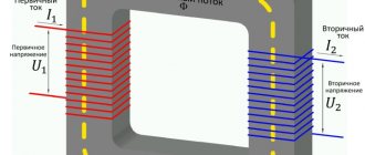
Let's consider the winding connection diagrams using the example of a three-phase transformer. In its structure, it has a magnetic circuit consisting of three rods. Each rod has two windings - primary and secondary. High voltage is applied to the primary, and low voltage is removed from the secondary and goes to the consumer. In the symbol, the connection diagram is indicated by a fraction (for example, Y⁄∆ or Y/D or U/D), the numerator value is the connection of the high voltage (HV) winding, and the denominator value is the low voltage (LV).
Each rod has both a primary winding and a secondary winding (three primary and three secondary windings). Each winding has a beginning and an end. The windings can be connected to each other using a star or delta method. For clarity, let us denote the above schematically (Fig. 1)
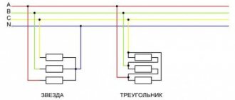
When connected by a star, the ends of the windings are connected together, and three phases go from the beginning to the consumer. From the terminal connections of the ends of the windings, the neutral wire N (also known as neutral) is removed. The result is a four-wire, three-phase system, which is often found along overhead power lines (Fig. 2)
The advantages of this connection scheme are that we can get 2 types of voltage: phase (phase + neutral) and linear. In such a connection, the linear voltage is √3 times greater than the phase voltage. Knowing that the phase voltage gives us 220V, multiplying it by √3 = 1.73, we get approximately 380V - linear voltage. But as for the electric current, in this case the phase current is equal to the linear one, because Both linear and phase currents leave the winding in the same way, and it has no other path. It is also worth noting that only in the star connection there is a neutral wire, which is a load “equalizer” so that the voltage does not change or jump.
Let us now consider the connection of the windings with a triangle. If we connect the end of phase A to the beginning of phase B, connect the end of phase B to the beginning of phase C, and connect the end of phase C to the beginning of phase A, we will get a triangle winding connection diagram. Those. in this circuit the windings are connected in series. (Fig. 3)
Basically, this connection scheme is used for symmetrical loads, where the load does not change between phases. In such a connection, the phase voltage is equal to the linear voltage, but the electric current, on the contrary, is different in such a circuit. The linear current is √3 times greater than the phase current. The delta connection of the winding provides ampere-turn balance for zero current
sequences. In simple terms, the delta connection circuit provides balanced voltage.
Let's summarize. For a basic definition of power transformer winding connection diagrams, it is necessary to understand that the difference between these connections is that in a star, all three windings are connected together by one end of each winding at one (neutral) point, and in a triangle, the windings are connected in series. The star connection allows us to create two types of voltage: linear (380V) and phase (220V), and in a triangle only 380V.
The choice of winding connection diagram depends on a number of reasons:
- Transformer power circuits
- Transformer power
- Voltage level
- Load asymmetry
- Economic considerations
For example, for networks with a voltage of 35 kV and more, it is more profitable to connect the transformer winding with a star circuit, grounding the zero point. In this case, it turns out that the voltage of the transformer terminals and transmission line wires relative to the ground will always be √3 times less than linear, which will lead to a reduction in the cost of insulation.
In practice, the following groups of compounds are most often encountered: Y/Y, D/Y, Y/D.
The group of winding connections Y/Y (star/star) is most often used in low-power transformers that supply symmetrical three-phase electrical appliances/receivers. It is also sometimes used in high-power circuits when grounding of the neutral point is required.
The winding connection group D/Y (delta/star) is used mainly in high-power step-down transformers. Most often, transformers with such a connection operate as part of power supply systems for low-voltage current distribution networks. Typically, the star's neutral point is grounded to accommodate both line-to-line and phase-to-phase voltages.
The Y/D (star/delta) winding connection group is mainly used in the main transformers of large power stations and non-distribution substations.
Source: www.forwardenergo.ru