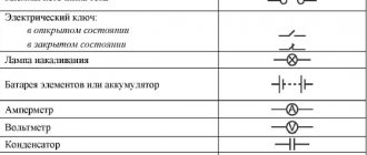
Vector diagram of currents and voltages
In general, for a better understanding of the procedures occurring in radio circuits and their relationships with each other, it is sometimes not enough to operate with the characteristics and parameters of a given circuit that have a digital display. Due to the fact that the bulk of circuits are characterized by variable values of applied voltage and flowing current, which are sinusoidal functions of time, a comprehensive answer to the state of the circuit can be given by its graphical presentation using a vector histogram.
Vector diagram of voltages and currents
Types of vector diagrams
Any characteristic of an electrical circuit that varies according to a sinusoidal or cosine principle can be displayed by a point on the surface in the corresponding system of quantities. The dimension along the X axis is the real component of the parameter, and the imaginary component is placed along the Y axis. It is these components that are included in the algebraic model of writing a complex quantity. Subsequent connection of a point on the surface and the zero point of the coordinate system will allow us to consider this straight line and its angle with the real axis as an image of a complex number. In practice, a positively directed segment is usually called a vector.
A vector diagram is usually called a set of positively directed segments on a complex surface, which corresponds to the complex values and parameters of the galvanic circuit and their relationships. By their nature, vector diagrams are divided into:
- Accurate histograms;
- Qualitative histograms.
The peculiarity of reliable histograms is the observance of the proportions of all characteristics and parameters obtained by calculation. These diagrams are used in checking previously carried out calculations. The use of qualitative histograms is based on taking into account the mutual influence of characteristics on each other, and basically they precede calculations or replace them.
Vector diagrams of currents and voltages visually display the process of achieving the goal of calculating an electrical circuit. If you follow all the rules for constructing vector segments, you can simply determine the phases and amplitudes of real characteristics from the histogram. Constructing high-quality histograms will help you control the correct process of solving the problem and easily determine the sector with the vectors being determined. Depending on the design features, graphic diagrams are divided into the following types:
- A pie chart, which is a graphical histogram formed by a vector that describes a circle or semicircle with its end, for any changes in the characteristics of the circuit;
- A line diagram is a graphical drawing of a straight line formed by a vector by changing the characteristics of a circuit.
Construction of a vector diagram of voltages and currents
To better understand how to construct a vector diagram of currents and voltages, you should consider an RLC circuit consisting of a passive element in the form of a resistor and reactive elements in the form of an inductor and a capacitor.
Circuit diagram with series connection of elements
Before constructing a vector diagram of currents and voltages, it is necessary to characterize all known parameters of the circuit. According to the circuit diagram shown in picture a:
- U is the magnitude of alternating voltage at the current time;
- I – current power at a given time;
- UA – voltage drop across active resistance;
- UC – voltage drop across a capacitive load;
- UL is the voltage dropped across an inductive load.
Since the input voltage U changes according to an oscillatory law, the current strength is characterized by the equation:
- Im – maximum current amplitude;
- ω – current frequency;
- t – time.
The total input voltage, in accordance with Kirchhoff's second law, is equal to the total voltage on all elements of the circuit:
According to Ohm's law, the voltage drop across a resistive component is:
The resistance to the current of the active element depends purely on the properties of the conductor and is not determined by either the current characteristics or the time aspect and, accordingly, has a phase shift identical to the voltage.
Since a capacitor in a circuit with an electric current varying along a sinusoid is characterized by the presence of reactive capacitive reactance, and due to the fact that the voltage on it constantly has a phase lag from the flowing current by π/2, the expression is appropriate:
- RC=XC=1/ωC;
- UC=Im*RC*cos(ωt-π/2), where:
- RC – capacitor resistance;
- XC – reactive impedance of the capacitor;
- C is the capacitance of the capacitor.
The inductive reactance of the inductor is determined by the presence of an electric current varying according to a sinusoidal law, and since the voltage at any period of time has a phase advance relative to the electric current by π/2, the formula describing the oscillatory process on the element looks like:
- RL=XL=ωL;
- UL=Im*RL*cos(ωt+π/2), where:
- RL – inductor resistance;
- XL – reactive impedance of the inductor;
- L – coil inductance.
Therefore, the total voltage applied to the circuit is:
- Um – maximum voltage value;
- φ – phase shift.
Due to the fact that voltage and electric current change according to a sinusoidal law, and their fixed indicators differ only in the phase shift, these quantities are constructed as vectors.
Subscriber service for metering center
Checking the connection diagram of the meter and current transformer (if available).
Pulling the contacts of the meter and current transformer (if available).
Removing the power profile from the meter and vector diagram.
Measurement of current in the secondary winding of current transformers.
Current measurement of each phase of the outgoing line.
Determination of the transformation ratio of current transformers by calculation.
Instrumental check of the electricity metering unit throughout the year, once a month -
100,700 rubles
VAT included;
Instrumental check of the electricity metering unit throughout the year, once every 3 months -
39,700 rubles
VAT included;
29,500 rubles
VAT included.
Prevents the occurrence of malfunctions and accidents;
Reduces the risk of sanctions for unmetered electricity consumption;
What is included in the subscription service for an electricity metering station?
Subscriber servicing of the electricity metering unit is carried out in order to monitor its operation. The specialist checks whether the metering device is working correctly, identifies and eliminates possible violations in its functioning. This helps ensure proper metering of electricity and also reduces the risk of fines for incorrect metering or unmetered energy consumption, which can be quite significant.
Vector diagram of currents and voltages
Digital representation of dynamic processes makes it difficult to perceive and complicates the calculation of output parameters after changes in input conditions or as a result of processing performed. A vector diagram of currents and voltages helps to successfully solve the indicated problems. Familiarization with theory and practical examples will help you master this technology.
Types of vector diagrams
Vector graphics are well suited for correctly displaying variables that determine the functionality of radio devices. This implies a corresponding change in the basic parameters of the signal along a standard sinusoidal (cosine) curve. To visualize the process, harmonic oscillation is represented as a projection of a vector onto the coordinate axis.
Using standard formulas, it is easy to calculate the length, which will be equal to the amplitude at a certain point in time. The tilt angle will indicate the phase. The total influences and corresponding changes in vectors obey the usual rules of geometry.
There are high-quality and accurate diagrams. The first ones are used to take into account mutual connections. They help make a preliminary assessment or are used to completely replace calculations. Others create taking into account the results obtained, which determine the size and direction of individual vectors.
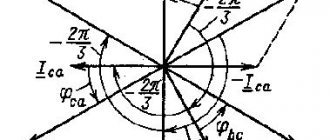
Let us assume that we need to study the change in current parameters in a circuit for different values of resistor resistance in the range from zero to infinity. In this circuit, the output voltage (U) will be equal to the sum of the values (UR and UL) on each of the elements. The inductive nature of the second quantity implies a perpendicular relative position, which is clearly visible in part of figure b). The triangles formed fit perfectly into the 180 degree circle segment. This curve corresponds to all possible points through which the end of the vector UR passes with a corresponding change in electrical resistance. The second diagram c) shows a current lag in phase by an angle of 90°.
Shown here is a two-pole element with active and reactive conductivity components (G and jB, respectively). A classic oscillatory circuit created using a parallel circuit has similar parameters. The parameters noted above can be represented by vectors that are constantly located at an angle of 90°. A change in the reactive component is accompanied by a movement of the current vector (I1...I3). The formed line is located perpendicular to U and at a distance Ia from the zero point of the coordinate axis.
Vector diagrams and complex representation
Such tools help to build visual graphic diagrams of oscillatory processes. A similar result is achieved by using complex numerical expressions. In this version, in addition to the axis with real values, an additional coordinate segment with imaginary values is used. To represent a vector, use the formula A * ei ( wt + f 0) , where:
- A – length;
- W – angular velocity;
- f0 – starting angle.
The value of the real part is A*cos*(w*t+f0). This expression describes a typical harmonic oscillation with basic characteristics.
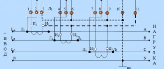
Installation and operation of meters - Checking that the meter is turned on correctly
It is important to understand that you can draw a conclusion about the correct switching on of the meter when the vector diagram taken at its terminals completely coincides with the normal one.
In order to be able to carry out this work correctly and efficiently, it will be necessary to ensure that the secondary circuits of the transformer are correct. Naturally, a person who has no experience in this area will not be able to perform such work.
And the one who will perform it must understand that there are a large number of formulas and diagrams on the Internet that are ready to help you with this procedure. Having familiarized yourself with them, you will be able to carry out this work quickly and efficiently without any problems.
In general, it should be noted that checking whether the meters are turned on correctly will consist of two stages: first of all, you will need to carefully check the voltage circuit and current circuit, and take a vector diagram.
After this, it is necessary to check the secondary circuit of the voltage transformer. And this point must be given especially close attention; this is the only way to achieve the desired result.
You must check that the phases are marked correctly. It is also important not to forget that this test must be carried out under operating voltage, current measurement without breaking the circuit being tested, and this point must be given as much attention as possible.
Example of a technical report
Electrical testing
You will need to carefully measure all line voltages, moreover, this also applies to the voltage of each phase separately, relative to ground. In general, the meanings of such checks can be very different, since everything here will depend on the connection diagram.
That is why it is necessary to approach their study competently and responsibly. And then all the work will be of high quality. In addition, you must be able to test transformer current secondary circuits.
When checking them, you need to know that if you swap the wires of the two outer voltage circuits on the terminal box, the meter should stop. But this will only happen if you manage to turn on the device correctly.
If the meter is turned on correctly, the pairing of current phases of the same name will be ensured. In general, as you might have guessed, there are a large number of ways to solve this issue. There are no unsolvable problems if an experienced specialist works.
You must remember that if the counter is turned on correctly, then each of its elements will necessarily rotate the disk to the right. If you need to correct the error, you will need to swap the wires that are connected to this element. If the device does not work, it is sent to an electrical laboratory.
It is important to understand that it is necessary to disconnect and connect jumpers only when the voltage is removed, since this is a particularly important point.
Below you can use the online calculator to calculate the cost of electrical laboratory services.