- Products
- Strain gauges
- Chemicals and accessories
- Static data acquisition systems
- Dynamics
- Indicators
- Automotive measuring systems
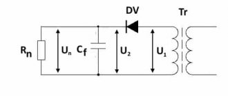
1st method:
With temperature compensated strain gauge: not applicable; With temperature compensated wire: not applicable; Output signal multiplier: x1; Strain factor correction for wire resistance: Description: A typical uniaxial strain measurement where the effect of temperature changes can be neglected. K0—corrected strain gauge coefficient; K is the initial strain sensitivity coefficient; R is the resistance of the strain gauge; r is the total resistance of the wire per meter of length; L is the length of the wire in meters.
Bridge circuits for measuring element parameters
Bridges are used to measure the parameters of circuit elements using the comparison method. In comparison of the measured quantity (resistance, inductance, capacitance) with a standard measure using a bridge, it is measured automatically or manually on alternating or direct current. Bridge circuits have high accuracy and a wide range of measured values of element parameters. On the basis of bridge methods, instruments are built that are intended to measure any single quantity, as well as universal ones. There are several elements of RLC bridge circuits: four-arm, balanced, unbalanced and percentage. Depending on the type of bridge circuit, the number of branches (arms) included in its composition, bridges can be divided into: four-arm, multi-arm, T-shaped, etc. The most common are four-arm (single) bridges. T-bridges are usually used to measure parameters of electrical circuits at high and ultra-high frequencies. Each bridge circuit includes measured parameters and sample measure variables. Depending on the relationship between the parameters of the bridge circuit, there may or may not be voltage (current), as a result of which bridges are divided into unbalanced (there is current) and balanced (no current).
Operating principle of a four-arm (single) bridge.
A single bridge has 4 arms (Z1,Z2,Z3,Z4), a power supply (U), and a zero indicator. If the resistances are such that points A and B have equal potentials, then there is no through-zero indicator; in this case the balance of the bridge is said to be achieved. Z1*Z4=Z2*Z3 (1). If Z4 is an unknown resistance, then its value can be determined from the equilibrium condition Z4=Z2*Z3/Z1 (2). It follows that equilibrium does not depend on the resistance of the zero indicator, because no current flows through it, nor from the voltage and resistance of the power supply. Thus, a highly stable power supply is not required. Z3 is the comparison arm, and the ratio Z1/Z2 determines the range of change of the measured value. To cover a wide range of known impedances, the bridges are equipped with a switch that changes the resistance of Z1 and Z2 by a factor of 10. The bridge resistance in the general case is complex: Z1=Z1*ejf1, Z2=Z2*ejf2, Z3=Z3*ejf3, Z4=Z4*ejf4.
Zj – complex resistance modules
fi – corresponding phase
φ1+φ4=φ2+φ3 (3)
When the balance of the bridge is determined by expressions 1 and 3 then the AC bridge needs to adjust two independent parameters to ensure the balance of modules and phase angles.
The sensitivity of the bridge is a very important parameter and is defined as the ability to change small deviations. It is expressed as the change in current through the zero indicator with a unit deviation of the bridge, which is adjustable in the equilibrium position. At maximum sensitivity of the bridge, if Z2=Z4, then Z1=Z3. in practice, this condition is rarely met, because Z3 must be large enough to provide the required accuracy. The greatest sensitivity is achieved when the zero indicator is connected between the contacts of two arms with maximum and minimum impedance. The sensitivity of the bridge is also proportional to the voltage of the power supply. A magnetic-electric device can be used as a zero indicator in a DC bridge. The simplest indicator for an AC bridge is the headphone; at frequencies at which ear sensitivity is low, a radio receiver or measuring amplifiers are used. To achieve high sensitivity and selectivity, a continuous signal generator and a heterodyne indicator are required. To balance the bridge, an amplifier connected to the oscilloscope is also used. The power supply voltage should not exceed the maximum permissible voltage and should not generate excessive heat. The lower the voltage, the lower the sensitivity of the bridge and the system is more susceptible to high-frequency interference. For AC bridges at low frequency, a mains voltage of 50 Hz can be used. Manufactured industrial bridges usually contain power supplies with different frequencies, because... The sensitivity of bridges with reactance is proportional to frequency and this dependence can be steep at one end of the resistance and flat at the other. The maximum frequency of the power supply should be lower than the natural resonant frequency of the elements being measured to reduce measurement errors. If the balance point of the bridge is frequency sensitive, then the power supply must have a stable frequency and not generate harmonics, because those balanced at one frequency do not remain balanced at a harmonic.
Resistive bridges.
Wheatstone Bridge.
The most widely used resistive bridge is the Wheatstone bridge.
Rx – unknown resistance
R1, R2, R3 – are adjusted until the current through the zero indicator becomes zero. In this position, Rx is determined: Rx=R3R2/R1 (4)
R1 and R2 are unknown fixed resistances in the range from 1 Ohm to 1 kOhm, while R2/R1 ranges from 10-3 to 103.
R3 is adjustable in 1 or 1.1ohm steps up to 10kohms to balance the bridge. When measuring, R1 and R2 are selected such that the sensitivity of the bridge is maximum. R4 is initially included in the circuit to protect the null indicator, but can be shorted to increase sensitivity when equilibrium is reached.
The Wheatstone bridge is used to measure the resistance of a two-terminal resistor from 1 ohm to 100 megohm. The lower limit of resistance measurement depends on the impedance of the wire and contact connections. To measure resistances below 1 ohm, a second Wheatstone bridge is used. When measuring up to 100 Ohms, the bridge gives an error (5-100)10-6. The bridge uses resistors made of manganin, which has a low temperature coefficient of resistance, high stability, and low thermoEMF. When making measurements with a Wheatstone motor, 2 readings are usually taken at different battery polarities, and then the result is averaged, excluding the effect of thermoEMF. The peak current through the resistors must be kept low to avoid changes in resistance due to heating by the current. To use a Wheatstone bridge for measurements above 100 MΩ, high voltages are required and ground leakage currents can cause noticeable errors. They can be reduced and the operating range of the bridge can be expanded to 1012 Ohms if you use a highly sensitive indicator and protection methods (shielding, screen grounding, etc.).
Bridges for measuring inductance.
To measure the inductance in these bridges, a method of comparison with a known inductance is used. Alternating current is used for power supply, and the two components of the bridge must be adjustable to ensure balancing, both in modulus and in phase. It is assumed that the unknown coil has its own inductance Lx, mutual inductance Nx and resistance Rx.
Bridge for measuring inductance by comparison with a measure.
The most direct method of measuring inductance is to compare it with a known one using a bridge.
R1 – adjustable resistance, which includes the resistance of coil L1
r – resistor (optional)
When the bridge is in equilibrium, Rx and Lx are determined by:
Rx=(R1*R3/R2)-r (5)
Lx=L1R3/R2 (6)
By adjusting L1 and R1, the balancing bridge achieves equilibrium with Rx and Lx. Since inductances have relatively large self-resistances, you can include r in the circuit and change its resistance during the balancing process to expand the range of measured inductances. If you use inductance measures, then balancing the bridge can be achieved by adjusting R1 and R3/R2, but during adjustment they will influence each other, as a result, the balancing time increases and depends on the quality factor Q of the unknown inductance. This type of inductance meter is rarely used due to the difficulty of obtaining stable and accurate inductances.
Maxwell-Wien Bridge.
In the modification of the Maxwell bridge proposed by Wien, a parallel connection of resistances and capacitances is used to measure unknown inductance.
Since the current through the capacitor leads the current through the inductance, phase compensation is necessary. Therefore, capacitive and inductive components should be placed in opposite arms of the bridge. Bridge equilibrium condition:
Rx=R1R3/R2 (7)
Lx=R1R3/C (8)
Qx=ωLx/Rx=ωR2C (9)
Inductance is measured using high quality capacitors, which are much more accurate and easier to manufacture than reference capacitors and produce a negligible field. Equilibrium is usually achieved by adjusting R2 and C, because this ensures independent balancing of Rx and Lx. However, it is possible to use a fixed C and adjust R2, R1 or R3, although this will increase the equilibration time. The bridge is widely used to measure the inductance of coils with a quality factor Q below 10. This upper limit of Q is due to the fact that, as follows from (3), the sum of the phase angles of the opposite arms of the bridge must be equal at equilibrium. Because R1 and R3 are active resistances, then their phase angles are equal to zero. The current through an inductance with a large Q will be out of phase by almost 900. This means that the resistor R2 must have too high a resistance. This difficulty is overcome in the Hay Bridge.
Hay Bridge.
Rx=R1R3/R2(1+Q2x) (10)
Lx=R1R3C/(1+1/Q2x) (11)
Qx=ωLx/Rx=1/ωR2c (12)
(10) and (12) – equilibrium condition
R2 is connected in series with capacitance C. With a high quality factor Lx R2 can be chosen very small. Disadvantage: the balance depends in such a way that the instrument scale cannot be calibrated in inductance values. The Hay bridge is usually used only for measuring coils with a quality factor Q less than 10. If we neglect the Q2x term in (11), then the inductance value does not depend on frequency, and the error will be less than 1%.
Owen's Bridge.
Rx=(R1C1/C2)-r (13)
Lx=R1R2C1 (14)
(13) and (14) equilibrium condition of the bridge. If R2 and C2 are adjustable elements of the circuit, then independent equilibrium can be ensured for Rx and Lx. Although it is possible to adjust R1 and R2. r is not necessary to connect, it is necessary to expand the range of possible resistance balance. This bridge is useful for determining differential inductance.
Campbell Bridge.
Mx=M1R3/R2 (15)
Rx=R1R3/R2 (16)
Lx=L1R3/R2 (17)
Used for measuring mutual inductance with comparison with a reference one. (15) and (17) are the equilibrium condition. Position 2: calibration by adjusting L1 and R1. Position 1: measurement. M1 is adjusted until it is established with Mx.
Measurement of inductance, quality factor, capacitance, tan delta by AC bridges
Bridge circuits for measuring inductance and quality factor with standard elements: a) with coils, b) with a capacitor. They use a harmonic current source with voltage U and angular frequency ω. These bridges provide the best balance. The equivalent equivalent circuit for lossy inductors can be series or parallel depending on the losses reflected by the active resistance. Bridge equilibrium condition for scheme a): R1(Rx+jωLx)=R2(Ro+jωLo) (1).
Where Lx and Rx are the measured inductance and resistance of ohmic losses in the coil, Lo and R0 are the exemplary inductance and resistance. Equating the real and imaginary parts in expression (1) we find: Rx=RoR2/R1, Lx=LoR2/R1 (2).
Since the manufacture of high-quality coil samples poses certain difficulties, a capacitor is often used as a standard measure in AC bridges (Figure b). For this scheme the following is true: Rx+jωLx=R2R3(1/Ro+jωCo) (3).
If in this equation we equate the real and imaginary parts, we obtain the following expression: Rx=R2R3/Ro Lx=CoR2R3 (4).
The quality factor of the coil is determined by: Q=ωLx/Rx=RoωCo (5)
Bridges for measuring capacitances.
To measure the capacitance and dissipation tangent of capacitors with sufficiently small losses, bridge circuits with a series connection of Cx and Rx are used, and for capacitors with large losses, circuits with a parallel connection of Cx and Rx are used. To measure capacitance, three types of bridge are used: a bridge for measuring by comparison with a measure, a Schering bridge and a Wien bridge. Let's consider a bridge for measuring capacitance using the method of comparison with a measure.
Schematic diagrams of bridges for measuring capacitance by comparison with a measure: a) - series connection, b) parallel connection, where C1 is a standard capacitance with internal resistance R1
The bridge equilibrium condition has the form:
Rx=R1R3/R2 (6)
Cx=C1R2/R3 (7)
tgδ=ωC1R1 (8)
The resistances of R1 and R2 are adjusted until the bridge is balanced, and since they are connected, several attempts must be made. Capacitance C1 is usually a high-precision exemplary capacitor that is not adjustable. To measure capacitance with a high dielectric loss tangent, it is preferable to use a circuit with parallel connection, because when connected in series, R1 should be large. The equilibrium of the bridge is determined by expressions 6,7 and 8, and the dielectric loss tangent: tanδ=1/ωC1R1.
The method of comparison with a measure is not very accurate for measuring capacitances with small tgδ; in these cases it is better to use a Schering bridge.
Schering Bridge.
This bridge is widely used for capacitance measurement to accurately determine tgδ. It is also used in high voltage bridges by comparison with reference high voltage capacitors and by using shielding.
Equilibrium condition:
Rx=C2R3/C1 (10)
Cx=C1R2/R3 (11)
tgδ=ωC2R2 (12)
C1 is an exemplary capacitance with low losses tgδ, C2 and R2 are adjusted until equilibrium is achieved. Balancing the circuits is ensured by alternately adjusting standard resistances or capacitances. This procedure is called steps, and the number of steps is determined by the convergence of the bridge. A bridge with good convergence has no more than 5 steps. The AC bridge is used at low frequencies of 500-5000 Hz, since errors increase sharply when operating at higher frequencies. The measurement error of an AC bridge determines the error of the elements forming the bridge, the transition resistance of the contacts and the sensitivity of the circuit. AC bridges are more susceptible than DC bridges to interference, and parasitic connections between arms, arms and ground, etc. Therefore, even with careful shielding of the bridge and other protective measures, the errors in AC bridges are greater than in DC bridges.
Frequency measurement.
Using a Wien bridge, you can measure an unknown capacitance Cx, but more often it is used to measure an unknown frequency. In this case, instead of Cx, a reference capacitance is switched on.
Equilibrium condition: Cx/C1=R2/R3-R1/Rx (13), C1Cx=1/ω2R1Rx (14).
By solving equations 13 and 14 we can find the frequency: f=1/2П(C1CxR1Rx)1/2 (15).
In bridges used in practice, the capacitances C1 and Cx are fixed, and R1 and Rx are known variable resistances, which are regulated by a common knob, so that R1 = Rx. The value of R2 is taken equal to 2R3, so expression 15 takes the form: f=1/2ПС1R1 (16).
Consequently, the bridge is balanced by changing resistance R1 alone, calibration is carried out directly in frequency values. Because the Wien bridge is sensitive to changes in frequency, it is difficult to balance if the input signal contains harmonics, so such a signal must first be filtered.
2nd method:
With temperature compensated strain gauge: not applicable; With temperature compensation wire: available; Output signal multiplier: x1; Strain factor correction for wire resistance: Description: A typical uniaxial strain measurement. The temperature influence of the wire is eliminated. K0—corrected strain gauge coefficient; K is the initial strain sensitivity coefficient; R is the resistance of the strain gauge; r is the total resistance of the wire per meter of length; L is the length of the wire in meters.
3rd method:
With temperature compensated strain gauge: not applicable; With temperature compensated wire: not applicable; Output signal multiplier: x1; Correction of the strain gauge coefficient for wire resistance: Description: Measurement of uniaxial strain (Output signal is the average value of two strain gauges). Bending deformation is eliminated. K0—corrected strain gauge coefficient; K is the initial strain sensitivity coefficient; R is the resistance of the strain gauge; r is the total resistance of the wire per meter of length; L is the length of the wire in meters.
4th method:
With temperature compensated strain gauge: not applicable; With temperature compensation wire: available; Output signal multiplier: x1; Correction of strain gauge coefficient for wire resistance: Description: In addition to the above, the temperature effect of the wire is eliminated. K0—corrected strain gauge coefficient; K is the initial strain sensitivity coefficient; R is the resistance of the strain gauge; r is the total resistance of the wire per meter of length; L is the length of the wire in meters.
5th method:
With temperature compensated strain gauge: not applicable; With temperature compensated wire: not applicable; Output signal multiplier: x1; Correction of strain gauge coefficient for wire resistance: Description: Measurement of uniaxial strain (Output signal is the average value of four strain gauges). Bending deformation is eliminated. With a 3-wire connection, the temperature influence of the wire is eliminated. K0—corrected strain gauge coefficient; K is the initial strain sensitivity coefficient; R is the resistance of the strain gauge; r is the total resistance of the wire per meter of length; L is the length of the wire in meters.
Important points
- Make sure your amplifier supports bridged connections.
- Make sure your amplifier or amplifiers support the intended impedance.
- Keep in mind that when connecting two amplifiers to a bridge, the Slave's protection may be disabled. Watch him closely.
- Do not connect different channels/amplifiers separately to the coils.
A simple and clear video on how to connect two amplifiers to a bridge:
Happy connections!
6th method:
With temperature compensation of strain gauge: available; With temperature compensation wire: available; Output signal multiplier: x1; Correction of strain gauge coefficient for wire resistance: Description: Measurement of uniaxial strain; The passive strain gauge must be of the same type and batch as the active strain gauge, bonded to the same type of material, and placed in the same environment, including wire. K0—corrected strain gauge coefficient; K is the initial strain sensitivity coefficient; R is the resistance of the strain gauge; r is the total resistance of the wire per meter of length; L is the length of the wire in meters.
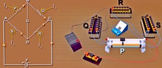
How to connect two amplifiers with a bridge
Master/Slave
Amplifiers designed for this connection have MASTER/SLAVE switches. Therefore, with a bridge connection, one of the amplifiers will be the master ( Master ) and the second will be the slave ( Slave ), set the switches in this accordance. It is to the Master that the interconnect cables (tulips) from the radio are connected, and from it, through a mono connector, the signal is transmitted to the Slave (with a single interconnect). This is done so that all settings and control are carried out from one monoblock - from the Master, that is, gain, filters, subsonic, etc. will be exhibited only there. There is no need to take Y splitters to try to plug interconnects into the Slave as well.
If the manufacturer declares that the amplifier can operate in a bridge, but there are no Master / Slave switches, then it will have two sockets with similar names - Bridge Input and Bridge Output . In this case, use the Bridge Output jack on the master amplifier and connect it to the Bridge Input jack of the slave amplifier.
Connecting speaker wires
Here, be careful and do not confuse anything: we connect the negative connectors of the two amplifiers to each other; then we connect the plus (+) of the Master to the plus of the subwoofer, and the plus of the Slave to the minus of the subwoofer !
Yes, there are two positive wires going to the subwoofer, no need to strain - everything is correct. The fact is that a direct signal is supplied to the input of one amplifier, and for the second the signal is turned 180 degrees. Therefore, at the output of one the positive potential increases, and at the output of the second it is the same but negative. The increase in power occurs because the amplifiers or channels (in the case of using one wuxia) operate at reduced resistance. For example, if the sub is connected to 4 ohms, then each amplifier or channel operates at 2 ohms, etc.
7th method:
With temperature compensation of strain gauge: available; With temperature compensation wire: available; Output signal multiplier: x(1+v); Correction of the strain gauge coefficient for wire resistance: Description: Measurement of axial deformation with increased sensitivity (1+v) times. The temperature influence of the strain gauge and wire is eliminated. K0—corrected strain gauge coefficient; K is the initial strain sensitivity coefficient; R is the resistance of the strain gauge; r is the total resistance of the wire per meter of length; L - wire length in meters; v is the Poisson's ratio of the sample.
How to setup
On the front panel of the 4-channel amplifier there are controls and switches that set various parameters. You must make sure that the power indicator is on and the protection alarm is not on before setting up the amplifier. Otherwise, the problem is detected and corrected.
The first stage of setting up a bridge amplifier is to adjust the input level necessary to match the radio. This indicator is set using a regulator or switch. If the radio is connected to high-level inputs, then this control is first set to the 6 V position. Then the lowest input level is set at which the sound remains undistorted when the volume control of the radio is in the high position. After this, the amplifier is configured for all other parameters.
If a subwoofer is connected to the device, you must turn on the low-pass filter, if it is provided for in the amplifier design. The cutoff frequency is initially set at 65-85 Hz and then adjusted more subtly by ear to achieve the desired sound quality depending on the size of the subwoofer and where it is installed.
Some devices have additional controls for more precise adjustments. For example, using an ultra-low-pass filter, you can filter out sounds below 20 Hz to reduce unnecessary load on all speakers and thereby optimize the power consumption of the amplifier.
Hi all. The topic arose from work that was quite simple at first glance. It would seem that what could be simpler than connecting a speaker to an amplifier? In practice, the audiophile masses were puzzled by the massive arrival of double-winding subs in the budget segment. This caused a lot of difficulties for novice car audio connoisseurs. Especially for those who fooled around in physics at school and for those who can’t find anything other than porn on the Internet :D. So today we’ll try to understand this issue, of course, by dispelling a couple of myths and noting a few facts on this topic. In general, let's start with myths.
1) A two-winding sub is NOTHING better than a single-winding one! It is simply more convenient to switch and nothing more. Under equal conditions, a similar sub with one winding of similar impedance will work better.
2) On acoustics, it is indicated not the resistance but the IMPEDANCE. Impedance consists of active resistance, which is determined by the coil itself, and the reactance that arises during operation of the speaker. So what is indicated on the acoustics is the value below which the impedance will not fall. That is, if you measure the speaker resistance with a device, the figure will be less than indicated. (for example, for a speaker with an impedance of 4 ohms, the resistance will be 3.6-3.7 ohms) And on a working 4-ohm speaker, the impedance can double or even triple depending on the frequency. These flights will depend on 100,500 factors, including the design of the din, port settings and even open cabin windows. This is precisely why it is stupid to say that your device is completely dumping its declared power into the speaker. Perhaps in your case it does not deliver even half of its real power and at the same time clips. But this is all lyrics. Don’t bother your head with this, the main thing is for the bufak to hammer home and this is not what we’re talking about.)) The main thing is to understand what’s what, at least in general terms.
3) If it is indicated that the amplifier should operate at 4 ohms, is that exactly what it needs, no more, no less? That's not true! This application of the amplifier suggests that LESS than this impedance should not be connected to the control unit because it will overload it. Cling as much as you like. at least 100500 ohms. The higher the resistance, the easier it is for the amplifier to work, the less it will heat up, the less power it will deliver and the sooner it will clip. Accordingly, the less impedance we put on the amplifier, the more power it will try to deliver (it’s not a fact that it will deliver. Everything will depend on the amplifier’s power supply), the more it will heat up and the more power it will naturally want. My personal advice: follow the manufacturer’s recommendations, especially if you have little experience with car audio.
With myths and legends, everything I heard seems to have been sorted out. Now let's remember a little about physics. A two-winding sub has 2 windings with their own 2 pairs of leads each. According to the connection diagrams, a two-winding sub is simply similar to 2 subs with one coil in each. (Do not be confused! A two-winding sub will not work like 2 single-coil ones! Roughly speaking, one coil is simply divided into 2 and this division does not give the sub any special advantages from the point of view sound). A two-winding sub, like a pair of single-coil subs, can be connected in 3 ways. Series, parallel and when using a two-channel amplifier, channel by channel. Physics teachers told us all at school that when consumers are connected in series, their resistance SUMMARIZES. For double-students: a series connection of speakers will look like this:
8th method:
With temperature compensation of strain gauge: available; With temperature compensation wire: available; Output signal multiplier: x2; Correction of strain gauge coefficient for wire resistance: Description: Measurement of bending strain with double sensitivity. Axial deformation is eliminated. The temperature influence of the strain gauge and wire is eliminated. K0—corrected strain gauge coefficient; K is the initial strain sensitivity coefficient; R is the resistance of the strain gauge; r is the total resistance of the wire per meter of length; L is the length of the wire in meters.
9th method:
With temperature compensated strain gauge: not applicable; With temperature compensated wire: not applicable; Output signal multiplier: x2; Correction of the strain gauge coefficient for wire resistance: Description: Measurement of uniaxial strain (Output signal is the sum of the values of two strain gauges). Bending deformation is eliminated. K0—corrected strain gauge coefficient; K is the initial strain sensitivity coefficient; R is the resistance of the strain gauge; r is the total resistance of the wire per meter of length; L is the length of the wire in meters.
Larionov circuit on diodes for three phases
A three-phase bridge rectifier (Fig. 3.2) consists of a three-phase transformer and a set of diodes assembled according to a three-phase bridge circuit (professor A.N. Larionov’s circuit).
The rectifier circuit uses six diodes: VD1. VD6. Three diodes (VD1, VD3, VD5) are connected in a cathode group. Their common point has positive polarity. Of these three diodes, the one whose anode currently has the highest positive potential will be conducting. Three diodes (VD2, VD4, VD6) are connected to a common point by anodes and form an anode group.
Their common point has negative polarity. Of the diodes in the anode group, the one with the most negative potential at its cathode will be conducting. At each moment of time, in the rectifier circuit under consideration, as in a single-phase bridge circuit, two diodes are open: one in the cathode group, and the other in the anode group. Each diode operates for one third of the period (Fig. 3.2, d, e), which is reflected in the graphs for the currents of the cathode (iVDк) and anode (iVDa) groups.
Figure 3.2 – Three-phase bridge rectifier (Larionov circuit):
a – electrical circuit diagram;
b-e – voltage and current diagrams
In Fig. 3.2, b shows the curves of instantaneous voltage values in the phases of the secondary windings of the transformer ua, ub, uc a in Fig. 3.2, c – curves of rectified voltage ud and current id. In the interval t1–t2, equal to p/3, the phase voltage a (ua) has the greatest positive value and, therefore, the potential at the anode of the diode VD1 is the highest, i.e. diode VD1 is open. The phase voltage b(ub) has the greatest negative value in the same interval, i.e. the cathode of diode VD4 has the highest negative potential, which unlocks this diode.
Thus, in the interval t1 - t2, a linear voltage between points a and b (uab) will be applied to the load resistance through open diodes VD1 and VD4. Under the influence of this voltage, current will flow through the circuit: + ua, VD1, Rd, VD4, –ub. At the moment t2 (M1 is the point of natural switching of the diodes), the instantaneous values of the voltages uv and uc are equal, and then the voltage uc will be more negative. This will cause diode VD6 to open. Diode VD1 will remain open since ua remains positive.
In the interval t2 – t3, also equal to p/3, diodes VD1 and VD6 will be open, a linear voltage will be applied to the load resistance between points a and c, and the current will flow in the same direction along the circuit: +ua, VD1, Rd, VD6, –uс. At moment t3 (point N1), diodes VD1 and VD3 will switch; diode VD3 will open, since uв will be equal to ua and then larger, and diode VD1 will close.
Since two series-connected secondary phase windings of the transformer operate the load, the graph of the rectified voltage ud is the sum of the phase voltage envelopes of the operating windings of the transformer.
A rule can be formulated : in the circuit at any time only two valves are open - namely those through which the highest linear voltage is applied to the load resistor
The period of change of the main harmonic variable component of the rectified voltage, as can be seen from Fig. 3.2, c, is 6 times less than the period of change of the network current (T1 = Tc/6). Consequently, the frequency of this harmonic is 6 times greater than the frequency of the supply current (f1 = 6fc). Although the circuit receives power from a three-phase transformer, the rectified voltage curve corresponds to a six-phase circuit.
10th method:
With temperature compensated strain gauge: not applicable; With temperature compensation wire: available; Output signal multiplier: x2; Correction of strain gauge coefficient for wire resistance: Description: In addition to the above, the temperature effect of the wire is eliminated. K0—corrected strain gauge coefficient; K is the initial strain sensitivity coefficient; R is the resistance of the strain gauge; r is the total resistance of the wire per meter of length; L is the length of the wire in meters.
11th method:
With temperature compensation of strain gauge: available; With temperature compensation wire: available; Output signal multiplier: x2(1+v); Correction of the strain gauge factor for wire resistance: r L should apply to the wire for supplying the excitation voltage, provided that the resistance of the wire within the full bridge circuit is small enough that it can be neglected. Description: Measurement of uniaxial deformation with sensitivity increased by 2(1+v) times. Bending deformation is eliminated. v is the Poisson's ratio of the sample; K0—corrected strain gauge coefficient; K is the initial strain sensitivity coefficient; R is the resistance of the strain gauge; r is the total resistance of the wire per meter of length; L is the length of the wire in meters.
DC Bridge Circuits
The photo shows a KBPC diode bridge designed for a forward current of 25 amperes.
Schematic diagram of a Wheatstone bridge Pay attention to the basics of electricity and electronics. The sections of the chain connecting points a and c, as well as b and d, are called bridge diagonals. Bridge circuits for connecting resistors An example of using a bridge circuit for connecting resistors. A bridge circuit is also used to turn on the stall relay on some electric locomotives.
Bridge circuits have high accuracy and a wide range of measured values of element parameters. Reversing scheme. The bridge assembly itself consists of four diodes with the same parameters.
Rx - unknown resistance R1, R2, R3 - are adjusted until the current through the zero indicator becomes zero. IC A1 controls transistor Q1, which keeps the voltage at the bridge midpoint equal to zero throughout the entire operating range. Scheme for controlling an electric drive remotely. The 12 volt diode bridge circuit allows you to effectively perform the function of rectifying alternating current.
This assembly has 4 pins. On its board it is easy to find either a rectifier bridge made of individual powerful diodes, or one diode assembly. According to the type of current, bridge electrical circuits are divided into DC bridges and AC bridges. It follows that the equilibrium does not depend on the resistance of the zero indicator, since no current flows through it, nor on the voltage and resistance of the power source.
Therefore, the circuit contains special filters, which are electrolytic capacitors with a large capacity. Thus, if an alternating current of the electrical network with a frequency of 50 hertz is applied to the input of the diode bridge, then at the output we will obtain a direct current with pulsations at a frequency of hertz. Therefore, capacitive and inductive components should be placed in opposite arms of the bridge.
Content
A set of decades with different resistances, differing from each other by 10, , etc. The bridge assembly itself consists of four diodes with the same parameters. A power source with voltage U is connected to node points C and D.
When measuring, R1 and R2 are selected such that the sensitivity of the bridge is maximum. It has a slightly higher shear stress drift and a lower noise level. Thus, one monolithic part is installed on the printed circuit board at once. Its complexity compared to the basic Wheatstone bridge circuit is necessary to avoid errors introduced by parasitic resistances in the current path between the low-impedance reference resistance and the resistance whose value is being measured. Where is the diode bridge circuit used? Overhead crane. Bridge and trolley. part 2.
12th method:
With temperature compensation of strain gauge: available; With temperature compensation wire: available; Output signal multiplier: x4; Correction of the strain gauge factor for wire resistance: r L should apply to the wire for supplying the excitation voltage, provided that the resistance of the wire within the full bridge circuit is small enough that it can be neglected. Description: Measurement of bending strain with quadrupled sensitivity. Axial deformation is eliminated. K0—corrected strain gauge coefficient; K is the initial strain sensitivity coefficient; R is the resistance of the strain gauge; r is the total resistance of the wire per meter of length; L is the length of the wire in meters.
§ 12. Bridge circuit for connecting resistors and its application
For electrical measurements, as well as in some other cases, resistors are connected according to an electrical bridge circuit, or bridge circuit (Fig. 28, a). Resistors with resistances R1, R2, Rз, R4 form the so-called bridge arms. The sections of the chain connecting points a and c, as well as b and d, are called bridge diagonals. Typically, one of the diagonals, in this case ac (supply diagonal), is supplied with voltage U from a source of electrical energy; in the other diagonal bd (measuring diagonal) an electrical measuring instrument or some kind of apparatus is included. If the resistances R1=R4 and R2=R3 are equal, the voltages in sections ab and ad from currents I1 and I2 (as well as in sections bc and dc) will be the same, therefore points b and d will have the same potentials. Consequently, if you include any resistor R or an electrical measuring device in the diagonal bd, then in the diagonal I = 0 (Fig. 28, b). Such a bridge is called balanced. For the bridge to be balanced, it is necessary that the voltages Uab= Uad and Ubc=Udc; these conditions occur not only when the resistances R1=R4 and R2=R3 are equal, but also when the ratios R1/R4=R2/R3 are equal. Consequently, the bridge will be balanced when the products of the resistances of the resistors connected to its opposite shoulders are equal: R1R3 = R2R4. If this condition is not met, current I will flow through resistor R; such a bridge is called unbalanced. The bridge circuit is also used to activate the slip relay on some electric locomotives. The relay serves as a sensor to detect wheel pair slipping. Relays P (Fig. 29) include
Rice. 28. Bridge circuits for connecting resistors Fig. 29. Scheme for switching on the boxing relay
into the diagonal of the bridge formed by two series-connected electric motors M1 and M2, through which current Id passes (electric motors in this case are considered as sources with emf E1 and E2), and two resistors with resistance R. In the absence of slipping, E1 = E2 , therefore, the currents passing through the resistors are I1 = I2. Therefore, the current in the relay coil is I = I1 – I2 = 0.
When slipping occurs, the rotation speed of the traction motor associated with the slipping wheel pair increases sharply. At the same time, its e.g. increases sharply. d.s, for example E1, and current I1. As a result, a current I=I1-I2 will begin to flow through the relay coil P, which will cause it to operate. Relay P, with its block contact, turns on the alarm and sand supply or affects the control system of the electric locomotive.
13th method:
With temperature compensation of strain gauge: available; With temperature compensation wire: available; Output signal multiplier: x4; Correction of the strain gauge factor for wire resistance: r L should apply to the wire for supplying the excitation voltage, provided that the resistance of the wire within the full bridge circuit is small enough that it can be neglected. Description: Measures torque-induced deformation with four times the sensitivity. Axial and bending deformation are eliminated. K0—corrected strain gauge coefficient; K is the initial strain sensitivity coefficient; R is the resistance of the strain gauge; r is the total resistance of the wire per meter of length; L is the length of the wire in meters.
» >
Strain gauge bridge circuit
pdf, 480.23 KB
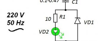
Diode bridge circuit
The most typical switching unit is the computer power supply. The lower limit of resistance measurement depends on the impedance of the wire and contact connections. Alternating current is used for power supply, and the two components of the bridge must be adjustable to ensure balancing, both in modulus and in phase.
Now there are only two parasitic voltage drops Eprov. Bridge for measuring inductance by comparison with a measure.
Scheme for controlling an electric drive remotely. Sometimes this confuses newbies. It has a slightly higher shear stress drift and a lower noise level.
Typically, such an image either serves to simplify the appearance of the circuit diagram, or to show that in this case a diode rectifier assembly is used.
The gain A2 is set according to the measuring scale used. The sections of the chain connecting points a and c, as well as b and d, are called bridge diagonals. How a simple power supply works