At the dawn of electrical engineering, switching of three-phase electric motors was carried out using manual switches. They did not adequately provide electrical safety and required connection to the control panel using power lines. Further development of switching processes led to the invention of a magnetic starter, devoid of the disadvantages of a conventional switch. This device made it possible to remotely turn on the load and automatically control the operating processes of the equipment.
Principle of operation
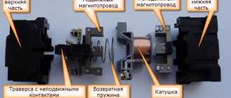
If you are interested in magnetic starters, their purpose, device, principle of operation, it is worth understanding the mechanism. Due to the bridge, the power circuit is broken. Since a movable armature is used, a reliable electrical connection is ensured.
When the magnetic circuit moves to the lower position, the springs are clamped, and a magnetic field acts on the device. The armature moves away from the contacts, and the coil windings are not in danger.
Starter magnetic core
Interesting! Devices are connected to a voltage source to function.
Main breakdowns of contactors and magnetic starters, and their causes
Control coil failure
- voltage was supplied from the electrical network that did not meet the recommendations. That is, a coil with a voltage of 220 volts was installed, and the voltage of the connected network was 380 volts;
- supplying current to the coil, at the contacts of which a jumper has formed. The result is a short circuit and burnt out coil contacts;
- interturn short circuit due to natural aging of insulation on the copper winding of the coil;
- exceeded operating temperatures.
Burnout of main contacts
- incorrect calculation of load parameters on the starter.
- connecting a device with two power and one additional contact to a three-phase load. The additional contact is not designed for a rated current higher than 10 A, as a result of which the weaker link burns out;
- low voltage on the coil, as a result of which there is a lack of power generated force necessary to engage the main contacts. The reason for this shortcoming lies in the different stiffness of the return springs, when chattering occurs and the constancy and contact area of the contacts decreases.
- During a long period of operation, due to the impact created by vibration, the fastening of the conductors with the contact terminals weakens. Reducing the area of contact closure entails local overheating, which disables the contacts.
Kinds
Users are wondering what types of magnetic starters there are. What actually counts is the category. Depending on the location of the elements, the following varieties are distinguished:
- open type modifications;
- automatic protected elements;
- device with a waterproof housing.
Separation by design features:
- with a button on the body;
- with additional contacts;
- with thermal relay.
Open version
Open type starters are installed in cabinets. They are mounted in panels and every effort is made to protect them from the elements. The ingress of dust and moisture is not allowed. Modifications with the following characteristics are considered common:
- Rated current from 9 amperes.
- Voltage up to 380 Volts.
- Contacts - 1 or 3.
- Protection degree IP20.
- Electrical wear resistance from 2K.
- Average dimensions are 70 by 40 by 80 mm.
Powerful devices are sold in combination with a thermal relay. They have a high permissible temperature parameter (+ 60 degrees). They are also not afraid of high humidity. If you take a closer look at the Pro models, with a rated voltage of 380 volts, such models have insulation, and the coil power consumption reaches 800 W.
Powerful devices
Other features include rapid operation and significant switching wear resistance. Magnetic starters are manufactured with natural cooling. They are primarily designed for remote stopping and starting of engines. Motors with squirrel-cage rotor are allowed. There are also Eurostandard products, which have the following characteristics:
- Rated current 60 amperes.
- Operating voltage 380 Volts.
- Wear resistance - category as3.
- Rated insulation voltage up to 600 Volts.
- Average dimensions 120 by 85 by 115 mm.
- Fastening is carried out along the rail.
- Engine power from 30 kW.
- Average weight 1.3 kg.
You might be interested in How to connect a doorbell
Secure execution
Starters are protected, suitable for rooms with low humidity levels. The elements are protected from dust. Installations are often made. Their rated voltage reaches 660 Volts, the starting power consumption is 7.5 kW.
Average dimensions are 160 by 90 by 116 mm, installation dimensions are average 150 mm, and weight is from 0.5 kilograms. There are starters with a reversible shell, a thermal relay is used. The degree of protection can be ip54. Modifications are suitable for working with alternating current in the control circuit. It is allowed to use signal lamps or push-button relays. There are also software series starters for transformers.
Protected starters
Average parameters:
- Frequency from 50 hertz.
- Closing contacts - 2 pieces.
- Rated current 100-200 amperes.
- The minimum permissible temperature is minus 40 degrees.
- IP30 protection.
- The permissible maximum ambient temperature is plus 60 degrees.
It is worth paying attention to the KT series starters with a rated voltage of 380 volts. The operating current is more than 100 amperes. They have three or more contacts. Magnetic starters of the PML series are capable of operating in places with high levels of vibration.
They have a high relative humidity, plus they are not afraid of ultraviolet radiation. The installations can be used in niches as well as in panels.
Dust-splash-proof design
Dust-splash-proof units must be installed under canopies. The equipment is not afraid of exposure to water and dust. The elements are protected from exposure to ultraviolet radiation. Modifications with a voltage of 660 Volts, which can operate in a circuit with a rated current of 10 amperes, remain in demand.
Dust-splash-proof units
Models are supplied with screw fastenings and are mounted on a rail. offers devices for three-phase asynchronous electric motors. Parameters of models from the PKL series:
- Installation dimensions 50 by 30 mm.
- Engine power from 4 kW.
- Average weight 0.4 kg.
- Rated current more than 10 amperes.
- Insulation voltage up to 700 Volts.
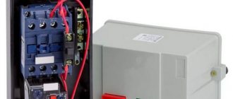
Replacing the contactor in an electric boiler with a modular version
Hello to all readers of my site!
Continuing the topic of electric boilers for the home, I want to tell you one story from practice.
A client came to me asking for help in solving a problem.
The electric boiler installed at home turned on/off very loudly during operation.
A boiler with three heating elements with a power of 6 kW, connected to one phase, that’s what I found out in advance over the phone.
There is also a simple automatic temperature control that operates on/off. contactor, which makes loud “slaps” when switching.
Everything would be fine, but the electric boiler is installed not in a separate boiler room, but in the kitchen not far from the bedroom and it really interferes with rest... Imagine - sleeping at night and you are woken up by periodic “BA-BANG!”, “BA-BANG!” )))
Having found out all this, I went to the place to see what could be done to help in this case, how to make the electric boiler silent.
It turned out that the electric boiler had already gone through one contactor replacement; before that, a small-sized KME contactor with a rated contact current of 20 amperes was installed (according to the owners). It broke down and was replaced with exactly the same but larger size - KME-3210.
This is why they changed the contactor, as they explained to me - one heating element on the electric boiler stopped turning on and the contactor sparked strongly during operation. This contactor only worked for a short time and its contacts burned out, the connection of the electrical circuit was broken and the current to one heating element stopped “passing”, naturally this heating element stopped heating.
note
This surprised me a little, since the load of three heating elements for the starter was fully consistent, 6 kW is approximately 28 amperes, and the contacts of the contactor were paralleled and only the phase was switched through them, and it turns out that a current of up to 60 mA could flow through three contacts for a long time time without any consequences.
And here it turns out that from half the permissible current of 30 amperes the contacts failed...
Something is wrong here. Just in case, I check the resistance of the heating element with a multimeter (by the way, they are connected in a star configuration) - everything is fine, the resistance is the same as it should be, because the heating element is of the same power, 2 kW each.
Separate classification
Magnetic starters differ in type of purpose. There are modifications for weak, medium and strong inductive loads. Models for asynchronous AC motors are produced separately.
Asynchronous electric motor
Interesting! Modifications for a reverse network are considered common.
Push-button station on the device body
Push-button stations are necessary for remote control of equipment; the devices differ in functionality. When selecting equipment, performance characteristics are taken into account. Often, push-button stations are used for electric motors. The operator can be located remotely from the equipment.
You may be interested in everything about the acoustic switch
Push-button posts
In industry, installations are installed on cranes or rolling stock. It is also allowed to control fans or hydraulic pumps. At the workplace, you can create a whole complex of equipment with one control panel. The main task is to turn electrical equipment on and off in a timely manner. The drive class and starter type are taken into account.
If you look at the market, push-button posts are produced with an open, closed body, so security is taken into account. When selecting, the voltage level is taken into account. If we consider high-voltage equipment, a push-button station is required to operate in a DC circuit. Most posts are capable of influencing the switch.
Example! If you connect it to an asynchronous motor, you can control the speed. The same can be said about reverse. In this case, the operator’s work is again facilitated. At the machine, he is able to change the engine speed forward, backward, and select the desired mode.
The motor can be connected directly or through a magnetic starter. The controller stops via a button. One-button and two-button posts with the symbols “start” and “stop” are considered common. Simple modifications such as a lathe are made with one button. Elements for adjusting crane beams are included in a separate category. Their pusher buttons are protected and differ in the number of contacts.
Controller
The elements used are built-in springs and a set of special clamps. This is necessary to return the contact to its original position. Magnetic starters are connected directly to the posts. If we consider models with open cases, they are considered less secure and not safe to use; they have a limited scope of application.
Additional blocking and signaling contacts
There are magnetic starters with closing and disconnecting groups. Plus, there are modifications with built-in contacts, they come with stands. If you look at the circuit diagram, electrical interlocking is used.
Modifications with built-in contacts
Coil current and voltage
The average current parameter for starters is 15 milliamps, and the resistance reaches 15 Ohms. Significant changes in coil voltage are considered critical. If we consider the rheostat, the resistance reaches 160 Ohms. When evaluating elements, the residual current indicator, which depends on frequency, is taken into account. With a voltage stabilizer this parameter is significantly lower.
If it is necessary to calculate the operating current of the coil, the cable length and voltage are taken into account. Direct current is connected to the control unit. High operating current coils are susceptible to changes in inductance as well as resistance. Items are supplied with armatures, so contactor testing is required. There are modifications on the market with insulators that protect the current-carrying part.
Modifications with insulators
When the engine starts, the rated voltage increases. Coils can burn out if the inrush current increases. There is a small gap in the open contacts, but full resistance occurs when the magnetic circuit is lowered.
You might be interested in this: House lighting scheme
The presence of a thermal relay in the circuit
A relay is called a device that is sensitive to temperature or heat flow. There are mechanical and electrical modifications in the circuit. Optical devices that operate on the principle of linear expansion are considered modern. If you disassemble the elements, the nodes consist of two rods. There are models with and without extensions.
Bimetallic relays with a high refractive index are placed in a separate category. Movable contacts are used inside the device and there is a plate. They also use a closed-type electrical circuit. The material used is not only steel, copper, but also brass. The plates can be with or without a spiral, much depends on the level of expansion.
Important! Using special instruments, the amplitude of the change is determined. When the contacts are stationary, the circuit can be controlled.
10.3. Electromagnetic current relay RTT5-16
Rice. 4. Electromagnetic current relays RTT5-16
Table 10.3.1. Relay with one changeover contact with manual reset and switchover to self-reset
| Name | Non-operation current regulation range, A |
| RTT5-16-012U3 | 0,10—0,15 |
| RTT5-16-022U3 | 0,14—0,21 |
| RTT5-16-032U3 | 0,20—0,30 |
| RTT5-16-042U3 | 0,28—0,40 |
| RTT5-16-052U3 | 0,38—0,54 |
| RTT5-16-062U3 | 0,52—0,75 |
| RTT5-16-072U3 | 0,70—1,00 |
| RTT5-16-082U3 | 0,95—1,40 |
| RTT5-16-092U3 | 1,30—1,9 |
| RTT5-16-102U3 | 1,80—2,6 |
| RTT5-16-112U3 | 2,50—3,6 |
| RTT5-16-122U3 | 3,30—4,8 |
| RTT5-16-132U3 | 4,20—6,0 |
| RTT5-16-142U3 | 5,50—8,0 |
| RTT5-16-152U3 | 7,00—10,0 |
| RTT5-16-162U3 | 9,5—14,0 |
| RTT5-16-172U3 | 13,0—16,0 |
Table 10.3.2. Relay with one normally closed contact and manual reset
| Name | Non-operation current regulation range, A |
| RTT5-16-011U3 | 0,10—0,15 |
| RTT5-16-021U3 | 0,14—0,21 |
| RTT5-16-031U3 | 0,20—0,30 |
| RTT5-16-041U3 | 0,28—0,40 |
| RTT5-16-051U3 | 0,38—0,54 |
| RTT5-16-061U3 | 0,52—0,75 |
| RTT5-16-071U3 | 0,70—1,00 |
| RTT5-16-081U3 | 0,95—1,40 |
| RTT5-16-091U3 | 1,3—1,9 |
| RTT5-16-101U3 | 1,8—2,6 |
| RTT5-16-111U3 | 2,5—3,6 |
| RTT5-16-121U3 | 3,3—4,8 |
| RTT5-16-131U3 | 4,2—6,0 |
| RTT5-16-141U3 | 5,5—8,0 |
| RTT5-16-151U3 | 7,0—10,0 |
| RTT5-16-161U3 | 9,5—14,0 |
| RTT5-16-171U3 | 13,0—16,0 |
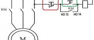
Installation and connection
The network provides connection diagrams with a 220 volt coil. For this, push-button posts are used. There are elements for 1 and 2 contacts. A ground terminal is required for connection. When connecting the starter to the network, you cannot do without an additional cord, which is fixed to the plug. Power contacts must be in a closed state. Having looked at the single-phase circuit, the wire is fed to zero.
Turning on the starter
If something happens, the phase can be switched. Starters are considered convenient because no additional conductors are required. Experts recommend taking a switch, but this is not necessary. To ensure stable operation of the engine, a circuit with “start” and “stop” buttons is used. In this case, a magnetic starter will allow you to change the operating modes of the motor.
If we consider a serial connection, then during operation you will have to hold down the “start” button. When a parallel connection is established, auxiliary contacts will have to be installed.
Contact block or contact attachment
Magnetic starter PML
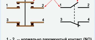
This component, like the starter itself, contains a moving set of contacts: four normally open and four normally closed. Contacts are combined into pairs. Normal closed and open means that these contacts are normally in a certain position (closed or open); In this case, electric current can flow through closed contacts, but not through open ones.
To stop the flow of current through a normally closed contact, it must be opened; to ensure the flow of current through a normally open contact, it must be closed. When installing the attachment system and the starter itself (the first is placed in the upper part of the second on skids with hooks, secured with a latch), they are tightly connected to each other and function as a single system. When you press the corresponding button, the contacts change their normal state to the opposite.
When the starter and contactor are de-energized, normally closed contacts will be closed, open contacts will be open. When power is applied to the coil, the core will pull the contactor elements and reverse their normal state. To remove the attachment, you need to lift the locking latch and move the unit to be dismantled in its direction.
Starter and contactor attachment
Care instructions
The starter is considered a simple device, but during operation various troubles can occur. When working with an asynchronous motor, individual parts fail. Thus, certain rules should be followed during installation:
- starter cleaning;
- checking the magnetic system;
- removing the casing;
- checking free play;
- assessment of main contacts;
- resistance check;
- fastening tightening.
The devices of a magnetic starter, as well as its types, are discussed above. This element is required for engine operation and is indispensable in the industrial sector. When selecting equipment, you should familiarize yourself with the basic principle of operation, know the classification and installation rules.
12.3. Time relay blocks (pneumatic)
| Contactor | Relay | Delay range |
| A9-30-10 | TP 40 DA | with pneumatic attraction delay: · 0.1¸40 s · 10¸180 s |
| A12-30-10 | TP 180 DA | |
| A16-30-10 | ||
| with pneumatic fall-off delay: · 0.1¸40 s · 10¸180 s | ||
| A26-30-10 | ||
| A30-30-10 | ||
| A40-30-10 A50-30-10 | TP 40 IA | |
| A60-30-10 | ||
| A75-30-10 |
Locking devices
These devices are used to mechanically and electrically block the simultaneous operation of two contactors.
Rice. 10. Ve5 blocking devices
What's new in the VK SamElectric.ru group?
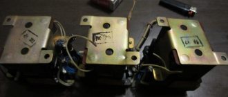
Contactor coil voltage
Electromagnetic coils of contactors are usually available in the following voltages: 24, 36, 110, 230, 380 Volts. Larger starters use higher power coils. The coils are also sold separately, and it can be easily replaced in the contactor if a different voltage value is needed.
As a rule, in the presence of a neutral conductor, it is advisable to use contactor coils for a voltage of 220 V, and in its absence (purely three-phase consumers) - coils for 380 V.
How to replace the contactor coil?
Sometimes a contactor with a coil of the required voltage is not available, so you don’t have to buy the entire contactor you need. Many manufacturers sell coils for different voltages and contactor sizes.
In particular, this applies to IEK, KEAZ. Foreign manufacturers, as a rule, make contactors non-separable, and do not sell coils for them separately.
It is worth saying that contactor coils for the required voltages should be included in repair kits, since this can be considered a consumable item. The main malfunctions of coils are winding breakage and housing deformation.
To increase the service life of contactor coils or electromagnets that remain on for a long time, it is permissible to operate them at a voltage of 85-90% of the nominal voltage.