31/10/2021
Iron
2
8 min
1 438
Hello, friends!
In my 20 years of experience as a computer technician, the motherboard is one of the most difficult components to diagnose due to the number of components connected to it.
If your motherboard fails, you may experience blue screens, freezes, beeping sounds, inability to detect USB drives and other hardware, and more.
This guide will teach you how to test your motherboard using a multimeter before installing other PC components.
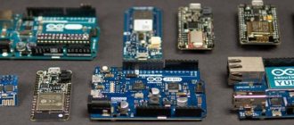
10 Best Unique Launchers for Android
Visual diagnostics
Radio components do not simply fail. And the consequences of their malfunctions can be seen visually. Let's look at the most common faults when they can be noticed visually.
Conventionally, all causes of malfunctions can be divided into 3 categories: moisture ingress, mechanical and electrical damage.
All of them can be interconnected, and even depend on each other. Let's take a closer look at each typical microcircuit malfunction with diagnostics and examples.
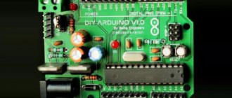
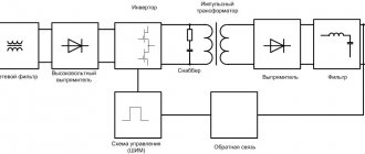
Design
If there is a 3D model for the device, testing is done using it. (Most often the device is assembled together in 3D CAD, there are tools for checking interference, making sections, etc.)
- Board shape - Compliance with the drawing, model, technical specifications
- Board thickness
- Fasteners
- Sufficiency (from the point of view of compliance with the clause of the ToR “external influencing factors”)
- Hitting places on the board
- Clearance for screw heads, washers...
- Connectors
- Position
- Orientation of the first legs
- Check the pinout with the mating boards
- Position of specific components
- Component height
Electrical damage
The microcircuit may fail due to a simple short circuit. Typically, holes may appear on such microcircuits. This is called thermal runaway.
Thermal breakdown is when a current passes through the microcircuit, which damages it so much that a hole appears on the housing. Those. it “burnt” and even smoked for a while. The hole in the case appears from a large amount of heat, which created a current passing through the microcircuit. The microcircuit is not designed for such a current, so its body cannot withstand it and begins to break down in a vulnerable area.
Below is a clear example of thermal breakdown of a stepper motor control chip (driver).
A heatsink was installed on the chip, but even this did not save the chip from thermal breakdown.
As a rule, such microcircuits completely lose their functionality. And with such a thermal breakdown, the tracks can be damaged. After soldering the damaged microcircuit, carefully look at the tracks and surrounding parts so that they are intact and without damage. The PCB may also swell, but this happens very rarely.
Also, if there is a short circuit, the microcircuits can become completely charred and leave traces of soot on the board and surrounding parts. Carbon deposits must be removed from the board because... it can conduct current.
Checking microcircuits with a multimeter
Another example of an absolutely similar malfunction can be found in laptops.
For example, on laptop boards, it is enough to accidentally short-circuit the USB port (or by static electricity), and the hub (group of chips) may immediately fail. And this is a 100% short circuit. And at the same time, the microcircuit will be visually without any damage. However, such microcircuits can be easily checked for serviceability with a multimeter.
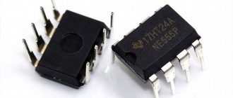
As an example, let's look at checking a microcircuit in a DIP package.
Each chip has power. And as a rule, it is this that fails if the microcircuit does not perform its functions.
Below is an example of the pinout of the NE555 timer chip.
This microcircuit (like any other) has power. Power is designated Vcc (roughly speaking plus) and GND (minus). Using a multimeter, you can check the integrity of the power supply, as if we were checking a regular diode for serviceability.
In the example below, a different microcircuit will be tested with a multimeter, but the essence is the same.
Switch the multimeter to dialing mode.
The continuity mode is usually shown as a UGO diode with a sound emission sign.
And now it’s enough to ring Vcc and GND (power supply) of the microcircuit.
Like a diode, it should not show zeros during a direct test (the positive probe of the multimeter to the plus (Vcc) of the microcircuit, the negative probe of the multimeter to the minus (GDD)).
Same with the reverse.
Of course, this method is not universal. For example, there are boards in which the wiring near the microcircuits can affect the measurements. Either you will have to unsolder the microcircuit from the board, or unsolder the parts or pins of the microcircuit so that they do not affect the test.
However, diagnosing the same laptops for the health of the video chip or hub is quite simple if you know their operating resistances and conditions. And there the influence of the components is not only great. It all depends on the fee.
Checking using service manuals
Each manufactured equipment has service manuals. Using them, you can check the performance of boards (and, accordingly, microcircuits) by following the instructions. For example, “Is there a voltage of 5V at pin number 12?” And then the next few steps that will lead to the final repair decision.
Although the service manuals recommend replacing the entire board at once, even without specific replacement of radio components.
Of course, it will not be possible to find a manual for any equipment due to various circumstances, but you can find equipment that uses a similar chip or board. Smartphones from different manufacturers may have the same power controllers. Therefore, experience and information search skills are important here.
Also, feel free to ask for information about chips on electronics forums and social media groups. (of course, before doing this, I independently searched for information in all available sources)
Typical connection diagrams
In addition to service manuals, there are also datasheets with simple shutdown diagrams. Those. Roughly speaking, you can assemble a circuit to simply test the functionality of the microcircuits.
Why does the microcircuit heat up and methods for diagnosing it
Another typical case of a short circuit is when the microcircuit gets very hot. Several options are possible here.
Most novice repairmen immediately declare that if the microcircuit heats up, then it is the one that is faulty. This is partly true, but only in rare cases. If the microcircuit heats up, this does not mean that it is faulty. But this is precisely what affects its functions and the overall performance of the board and the device as a whole.
As an example, consider the situation with power controllers on smartphones. These microcircuits control the power supply to the entire device. And it is through it that all currents pass. Let's say the microcircuit gets hot and you change it. And again the same problem. But the problem turned out to be not in it at all, but in another part of the board, where there is a short circuit.
A large current passes through the microcircuit precisely to that part of the board where the faulty radio component is located, which causes the microcircuit to heat up greatly.
You can either visually find a faulty shorting part (it may be damaged, with traces of oxide, darker, with traces of rust, etc.), or by the heat generated.
If problems may arise with visual detection (without a microscope, finding a damaged SMD capacitor or resistor on a board is quite problematic + attention is needed), then with detection by the heat generated, everything can be much simpler.
Of course, there are different cases here too. Heating from 2 A is one thing, and heating from 20 mA is another thing. Although the nature of the faults may be identical, different diagnostic methods will have to be used.
Diagnostics using a cash receipt
Connect the board to a laboratory power supply with short circuit current limitation. This is necessary in order not to completely finish off the heating chip. Next, we lean the cash receipt against the board.
And as a result, you can see on paper the silhouette of the part that is causing the short circuit.
Naturally, there will be a trace from the heating of the microcircuit, but the microcircuit itself is heated by another faulty part.
You can also use a freezer to freeze the board to quickly determine the point on the board where the short circuit is located. There can be four possible outcomes:
- The heating of the microcircuit occurs due to a short circuit in another part of the board. In this case, it is not the microcircuit itself that is faulty, but another radio component. The microcircuit simply stands in the way of a large current and passes it through itself;
- Both the microcircuit and other radio components are faulty. It so happened that a faulty radio component finished off the microcircuit. It cannot constantly heat up, and sooner or later it will fail;
- Still, the microcircuit itself is faulty. Yes, it happens. especially if there is a problem with contacts;
- There are traces of moisture on the board. . Next we will analyze such cases.
First sheet
- Checking project settings:
- revision (The revision field in properties is used subsequently to generate documentation)
- compiler settings (should be configured in the project by default) (Compilation settings in Altium - what is possible, what is not. Usually we create a project from an internal template in which everything is already well configured)
- Compiling the project (are there any errors)
- Connectors: (we rely on the technical specifications and additional wishes in the spirit of “as on the XX board”)
- type
- pinout
- correspondence of the number to the number on diagram E4
- Blocks on the first sheet:
- functionality coverage (All functions described in the technical specifications are implemented)
- quantity if multi-channel
- synchronization of sheet symbol outputs
- Design (Design is important. An incompletely completed scheme will not pass the test)
- Main inscription
- Arrangement of blocks, signatures, connections
Mechanical damage
Mechanical damage to microcircuits (and radio components in particular) is extensive. This may be the consequences of impacts on the device body, and careless operation and repair.
Hull damage
A typical example of hull damage.
The case can be damaged with tweezers simply by squeezing it. But this is a controversial situation. The microcircuit may be in good working order if there are no cracks on its glass base, even if the case is seriously damaged.
And here is an example of the final destruction of the microcircuit. Complete replacement only.
Damage to surrounding parts
The microcircuit cannot work without the “piping” - radio components that create the conditions for operation.
SMD capacitors are very easy to remove with tweezers. Be careful when replacing modules on smartphones.
Contact dump
The circuit will not work if the contacts with the radio components are damaged. Among the main standard microcircuit packages (DIP, SMD, BGA), BGA is the most difficult to visually evaluate for contact failure.
The contact drop can be from a microcircuit (small microcircuits are for power supply, memory, modems on smartphones):
There are no solder balls on the contacts of the microcircuit.
And here is an example of a blade already in contact with a microcircuit (i.e. the ball remains on the microcircuit), and with damage (large microcircuits are usually motherboards).
As you can see, large BGA contacts most often take pieces of the board with them.
In principle, the blade can be attributed to mechanical damage, but the blade can also be attributed to poor soldering quality.
Blade diagnostic methods
Warming up the board can be a diagnostic option, but not a repair option.
Checking new components
- Checking against the list from the task (When setting up a task for review, the author creates a list of newly created components so that the Reviewer does not miss anything. It is considered that the remaining components have already been checked by us earlier.)
- Check on Datasheet:
- Contact numbers
- Purpose
- Matching links to descriptions (a link to the component description must be in the component properties)
- Seat (must correspond to the specified partnumber)
- Partnumber (quite complete, no errors)
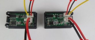
Multi-function voltage indicators - screwdrivers
Such devices are now mass-produced by industry. They allow you to perform 5 basic functions when working with electricity. One of them is resistance measurement, which is carried out by connecting the controlled area through a circuit created between a person’s fingers.
The design of such multifunctional devices for measuring resistance uses:
- batteries with a total voltage of 3 volts
- bipolar transistor amplifying the indication current signal
- LED, the glow of which indicates the passage of current through the section of the circuit being tested
- screwdriver tip serving as a contact pad
The low-power voltage sources of these devices are capable of delivering only low currents to the circuit, which, when amplified by a transistor, reach only tens of milliamps. This is quite enough for the LED to glow. However, they can be used to check the integrity of fuses, light bulb filaments and similar simple devices. When making measurements in complex circuits, multifunctional indicators do not work correctly because they are able to ring high-resistance areas created by low environmental resistance. This main drawback often misleads electricians.
conclusions
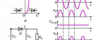
To summarize, I can simply say: ANY active load when measured has its own resistance, which will be greater the smaller the currents flow in it; in fact, the relationship is the opposite. And accordingly, when we measure resistance, we can indirectly imagine how large the currents flow in this section of the circuit. Thus, when one of the semiconductors goes into a short circuit, for example a bridge diode or a transistor in the hot part of a switching power supply, we get a blown fuse due to abnormally increased currents.
If these were secondary circuits, most often the power supply protection simply trips there and the device simply does not turn on until the short circuit, which causes very high consumption, is eliminated. So when electricians say that almost any breakdown, with rare exceptions when the parameters of parts float away, for example, dried electrolytic capacitors, and accordingly increased ESR of the EPS, we are left with only 2 breakdowns:
- There is a contact where there should not be one, or in other words, that same short circuit, often bypassing the load, because the current flows along the path of least resistance or through our burnt-out, for example, pn junction of the transistor.
- Either there is no contact where it should be, there is an open circuit, the load burns out, or the power semiconductor goes into an open circuit rather than a short circuit, which, by the way, happens in a much smaller percentage of cases when semiconductors burn out.
In this article, I tried to explain the logic of troubleshooting through the eyes of a repairman, since we see it by conducting diagnostics, analyzing the circuit and checking the multimeter readings and conditionally keeping in mind the resistance values for each specific part in good and bad condition. Look for a lot of additional information in the REPAIRS section of the website. Happy repairs everyone! AKV.
- DIAGNOSTICS AND COMPONENT REPAIR OF ELECTRONICS
- REPAIRING A PHONE THAT WILL NOT CHARGE
- CIRCUIT REPAIR: DISASSEMBLY-INSTALLATION, SELECTION OF ANALOGUES
- SEARCHING FOR THE CAUSE OF DEVICE MALFUNCTION
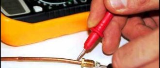
Rules for using the dialer
The only rule that needs to be remembered is that the dialing process is allowed only in a completely de-energized circuit.
Note! If you check live wires, you can get an electric shock and, in some cases, cause a fire. Below we describe in detail how to check the wire with and without a multimeter
Below we describe in detail how to check the wire with and without a multimeter.
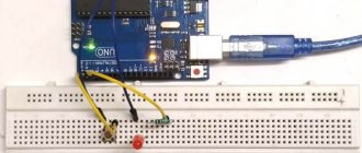
How to properly test wires (with a multimeter and without instruments)
Step-by-step work process:
- before starting work, you must turn the multimeter handle to the desired position;
- connect the ends of the probes to the required sockets. The black probe goes into the socket marked COM (in some cases indicated as “*” or ground point), and the red one goes into the socket marked Ω (sometimes indicated as R). It must be emphasized that the symbol Ω can be drawn either alone or in combination with the designations of other signs (V, mA). This arrangement of wires will help maintain polarity when making future measurements;
How to connect probes
- turn on the multimeter. Basically, there is a separate button for this or work can start automatically when the handle is turned to the required position;
- close the measuring ends to each other. If a beep is heard, the device is working correctly;
- take the wire to be tested (strip it of insulation in advance). Touch the exposed parts of the cable with measuring probes;
- If it is working properly, a sound will sound and the multimeter readings will be zero or show resistance. If the screen shows 1 and there are no sounds, it means that the tested cable is broken.
You can ring the wires without using a multimeter. To work you will need:
Diagram of a device with a light bulb
- a classic battery (it is advisable to take a 4.5-volt square battery);
- a regular 4-volt light bulb, through which the linear section of the cable is diagnosed (monitored);
- A pair of jumper cables and a breathtaking looking connector.
After preparing the tools for work, you need to use them to assemble a simple measuring circuit. If the circuit is correctly assembled and the wire is in good condition, the lamp will work. If there is a defect in the area, the light will not light up.
Nutrition
- General logic for the location of sources and loads (The layout should be logical and not complicate the board)
- Powering complex consumers through each other (One source for several consumers that can interfere with each other)
- Continuity (bottlenecks) (Thin bridges at polygons, number of vias when moving from layer to layer)
- Conductor cross-section (Highlighting all supplies in turn, viewing leads to each consumer)
- Ground (Ground is very important, if current flows through the power bus to the consumer, it needs to return back)
- Crosstalk between supplies, proximity of sources
- Power supply for microcircuits
- Presence of blocking capacitances at pins
- Power conductor thickness
- Separate Via for each consuming pin
- Via in ThermalPad (sometimes necessary)
- Power supplies
- Open the Datasheet, check the recommended topology (if it is not there, we discuss the optimal layout)
Checking seats
- Availability of a list of new (updated) seats. When checking again, the list must be new. (The principle is the same as for UGO)
- Checking the footprint with the description in the Datasheet
- Pin order
- Quantity
- Distances
- Form of platforms
- Silk-screen printing 0.2, first leg circle thickness 0.5, diameter 0.25 (design is important)
- Availability of a 3D model, matching legs, silk-screen printing with it (3D models allow you to additionally check the correctness of the seat, participate in the development and verification of the design, and help obtain beautiful renderings of boards)
Types of markings
On components produced during the Soviet Union, it was customary to indicate the denomination on the body of the part (see Fig. 1). This option did not require decoding, but if the integrity of the structure was damaged or the paint burned out, problems with text recognition could arise. In such cases, you could always turn to the circuit diagram that supplied all household appliances.
Figure 1. “ULI” resistor, the part rating and tolerance are visible on the body
Multimeters, testers
For the convenience of performing electrical measurements, combined instruments are used on the basis of an ohmmeter, allowing one to estimate resistance values on scales:
- Omov
- kiloohms
- megaohms
They have one precise measuring head, which, using shunts or additional resistances connected by a system of various mode switches, can work as:
- ohmmeter
- ammeter
- voltmeter
For each mode, the general scale has its own digital graduation in the corresponding units. Three combined functions of measuring resistance, current and voltage gave rise to the name of such devices:
- multimeter (derived from the words “many” and “measure”)
- avometer (short for ampere, volt, ohm, measurement)
- tester (denotes the ability to conduct “tests”)
Modern devices operate both on the basis of processing analog values and using digital technologies. Most models are equipped with a display, which immediately displays the value of the measured parameter. This is convenient because:
- makes reading easier
- no need to deal with scale graduations
- there is no need to do additional mathematical calculations
However, the principle of applying voltage to the measured section of the circuit and measuring the amount of current flowing through the resistance remains the same in all devices. An electrician who has a good understanding of how Ohm's law works will always understand the purpose of switches and methods of displaying information on any device, and will correctly measure resistance.
Silkscreen printing
- Default font, height 1mm, thickness 0.2mm
- Correct placement of inscriptions - not under the housings, not on the holes, not on each other (This is convenient to look at in 3D)
- The orientation of any inscriptions on one layer is only 0-90 or 0-270 degrees
- Designation of the first pin of microcircuits and connectors
- Designation of 5-10 multiple pins and rows on BGA for large chips (will help you find the right pin during debugging)
- Indication of the purpose of connectors and test points (helps with debugging)
- Correct sequence in groups (when the designations are moved to the side by the group due to the density of the components)
- Logo, board name, SVN revision, date (There is often a customer requirement to place their logo, decimal number, etc. AD makes it possible to set text fields defined by variables, we actively use this)
Design Rules
- Thickness of the metallization layer (In the stack settings everything should correspond to reality)
- Compliance of design rules with technological standards for selected board and metal thicknesses (minimum clearance/conductor, holes)
- Availability of specific standards for the classes of circuits highlighted in the diagram (clearances up to high voltages, minimum conductor thicknesses, etc.)
- Spacing from non-plated holes on inner layers (different from normal clearance)
- View all rules (All rules are reviewed one by one, searching for anything unusual)
- DRC settings (checking if the required checks are included in the DRC)
- DRC (The reviewer runs DRC; if it fails, the review stops)