The main element of the transformer is the magnetic circuit. This is a system through which the magnetic flux is closed, which serves as the basis for attaching windings and other elements of the device. Plates made of thin electrical steel serve as structural elements for assembling transformers. They are insulated using a heat-resistant coating, which is applied by the manufacturer, or varnish, applied after stamping the plates.
Design features
This is a very useful device. A transformer is a device that consists of a core with two windings. They must have the same number of turns, and the core itself is made of electrical steel. Voltage is applied to the input of the device, an electromotive force appears in the winding, which creates a magnetic field.
The basic principle of operation of the device.
The turns of one of the coils pass through this field, due to which a self-inductive force arises. In the other, a voltage arises that differs from the primary by as many times as the number of turns of both windings differs.
With its help, we can easily reduce the voltage and current in AC circuits. The advent of transformers made the transmission of electricity over long distances a practical reality. Transformers make it possible to reduce losses on the wires of power lines (connecting generating stations with loads) to reduce alternating current.
At both ends (both the generator and the loads), transformers step down voltage levels to safer values and reduce the cost of the equipment involved.
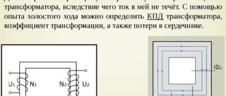
A step-down transformer can be of various types and types: single or three-phase, with an open housing or with a protective casing. One of the most important characteristics of the device is the transformation ratio, which should not exceed 1. Basic facts about step-down transformers are shown in the figure below.
Basic facts about step-down transformers.
Depending on the modification, the device converts electric current of different initial voltages, which can reach 660V. The transformer that steps down to 220V is most widely used. There is also a transformer that steps down to 380 volts.
A magnetic core is a set of elements of ferromagnetic material (usually electrical steel), which are assembled in a certain geometric shape. The main magnetic field of the step-down transformer is localized in it.
The entire magnetic system, together with all its components, is called the core. In this case, the part where the main windings are located is called the rod. And the part needed to complete the magnetic circuit is the yoke.
In accordance with the arrangement of the rods in space, the step-down transformer can have a flat, spatial, symmetrical or asymmetrical magnetic system.
In accordance with the requirements for each case, the output voltage can be different: for example, a transformer that reduces to 36 Volts, as well as 12, 24, 42V, etc. The video describes in detail the principle of operation of the device.
Which core is better
Step-down voltage transformers differ in their design features. Manufacturers make a choice in favor of one of two concepts - armored or rod.
The fundamental difference between the technical solutions is that in the first case, the windings are enclosed in an armor-type core, and in the second, the core is enclosed in rod-type windings.
Moreover, in devices of the first type, the axis of the windings can be located vertically or horizontally, while in the second case, the axis is placed vertically.
It will be interesting➡ Design and circuit of a three-phase transformer
However, the production method does not affect the performance and reliability of the device. The enterprise chooses the option that it considers best from the point of view of organizing the technological process.
Core and coils of a step-down transformer.
The influence of poor quality assembly on product characteristics
The most common defect in the assembled structure may be poor joining of the yoke to the rod plates. As a result, the resulting gaps will lead to an increase in the no-load current (Iхх) of the transformer. The magnetic flux will also deteriorate.
If, when assembling the product, the number of plates included in the yoke is less than required, this will cause a decrease in the cross-section, which will provoke an increase in magnetic induction and an increase in no-load losses. Any mechanical damage to the magnetic circuit plates during fusion will also cause a deterioration in the technical parameters of the transformer.
Operating principle
The principle of operation of a step-down transformer is based on the use of the phenomenon of mutual induction, which acts through a magnetic field and ensures the transfer of electricity from one circuit of the device to another. The transformer works like this:
- The current passes through the primary coil, which creates a magnetic field.
- All power lines are closed near the coil conductors.
- Some of these power lines close near the conductors of another coil. It turns out that both are connected to each other using magnetic lines.
- The farther the windings are located from each other, the less force the magnetic coupling occurs between them, since fewer power lines of the first cling to the power lines of the second.
- An alternating current passes through the first (which changes in time and according to a certain law), which means that the magnetic field that is created will also be variable, that is, change in time and according to the law.
Due to the change in current in the first, a magnetic flux enters both coils, which changes magnitude and direction. An induction of alternating electromotive force occurs. This is stated in the law of electromagnetic induction.
If the ends of the second are connected to electricity receivers, then a current will appear in the chain of receivers. The first will receive energy from the generator, which is equal to the energy given to the second chain. Energy is transmitted through alternating magnetic flux.
Circuit of the simplest toroidal step-down transformer.
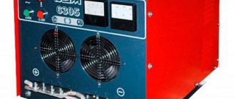
A step-down transformer (220B 110V) ensures the normal operation of equipment and electrical appliances that are manufactured in countries where power supply network standards differ from the Russian standard.
Step-down voltage transformers have a wide range of applications, but most often they are used in power supplies for various devices and in electrical networks. The choice of a specific device must be made taking into account certain requests for each individual case.
Any of the considered types of transformers can be used for the opposite purpose (connect the secondary winding to an alternating voltage source, and the primary winding to the load).
In this case, the transformer will perform the opposite function: the step-down transformer will function as a step-up transformer, and vice versa. However, for a transformer to operate efficiently, the inductances of each of its windings must be designed for specific operating ranges of voltage and current.
Therefore, when using a transformer for the “opposite” purpose, the voltages and currents of its windings must remain within the original design parameters. Only then will the transformer be effective (and not be damaged by excessive voltage or current!).
Transformers are often designed in such a way that it is not obvious which wires belong to the primary winding and which to the secondary winding. To avoid confusion, many transformers (mostly imported) use the designation “H” for the high-voltage winding (primary winding in a step-down transformer, secondary winding in a step-up transformer), and the designation “X” for the low-voltage winding. Therefore, a simple power transformer will have wires labeled "H1", "H2", "X1" and "X2".
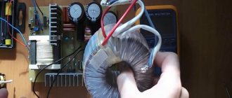
Material on the topic: how a toroidal transformer works and what are its advantages.
Checking a step-down transformer with a multimeter
Let's say a 4-pin transformer - two wires from the primary winding and two from the secondary. Checking it comes down to identifying damage in the windings. To determine whether there are any, first we’ll switch the multimeter to diode testing mode or move the switch to the resistance scale. Then we check one coil, without paying attention to the polarity of connecting the probes, since in this case it is absolutely not important. We do the same with the second one.
Low ohmmeter readings will indicate the serviceability of the windings; lack of tester response will indicate the opposite.
If the affiliation of a particular contact to any of the windings is not known, then it is established during the testing process - the resistance in the primary of the step-down transformer should be slightly higher.
Practical significance
The practical significance of the above becomes more apparent when the alternative is considered: before the advent of efficient transformers, conversion of voltage and current levels could only be achieved through the use of installations containing motors and generators.
While both the motor and generator are quite efficient units, using them in combination does not provide sufficient efficiency, so that the overall efficiency of the installation is in the range of 90% or less.
Transformer circuit in a simple charger.
In addition, the moving parts of these installations are subject to friction and mechanical wear, which in turn affects both service life and performance. Transformers, on the other hand, are capable of converting alternating voltage and current with very high efficiency without moving parts, making possible the widespread distribution and use of electricity that we take for granted.
It's fair to say that motor/generator units are not necessarily obsolete compared to transformers in all applications.
While transformers are clearly superior to motors/generators in converting AC voltage and current, they cannot convert one frequency of AC to another, nor can they convert (by themselves) DC to AC or vice versa.
It will be interesting➡ What is a transformer?
Motor/generator setups can do all this with relative ease, although with some of the efficiency limitations described above. These installations also have the unique property of storing kinetic energy.
That is, if for any reason the motor's power supply is instantly turned off, its angular momentum (inertia of rotational motion) will continue to maintain the rotation of the generator for some time, thereby isolating the load (powered by the generator) from “failures” in the main power system.
What are its advantages and disadvantages
Any electrical device has a number of advantages and disadvantages. Single-phase electrical transformers are no exception to this. They have more advantages than disadvantages. The main ones are:
- have one of the highest coefficients of performance (efficiency), which is 98%;
- They cool well and have increased resistance to overloads and short-term power surges;
- environmental safety of dry type. There is no oil in them, which means that nothing can harm the environment even after disposal;
- no need to comply with special fire safety measures at transformer installation sites;
- relatively small sizes, allowing the devices to be installed in small compartments.
You may be interested in this Procedure for replacing an electric meter
These devices are not without a number of disadvantages, which depend on their type and place of use:
- difficult maintenance if the device is oil-based. It should be regularly checked for breakdown and leakage of rubber gaskets, the replacement of which is quite difficult;
- dry single-phase devices do not tolerate high humidity, wind, chemical and physical influences, as well as pollution;
- high cost of dry transformers compared to oil transformers.
Conventional device for single-phase networks
Application area
Today, many appliances used in everyday life require reduced voltage. These are modern televisions, personal computers and laptops, and various gadgets.
However, these devices either come complete with a transformer, called a power supply, or it is built into the device. But lighting is a separate issue.
Halogen or LED lamps (especially those installed in rooms with high humidity) require a separate voltage reduction device. This is due to safety requirements, although efficiency also plays an important role.
When purchasing a transformer for 12 volt LED lamps for the bathroom, you need to pay attention to the IP protection class. The device must be protected from splashes to avoid short circuits and failure. For a living room or bedroom, this requirement is not significant.
Purpose
The main use of a step-down transformer is to produce low voltage to power an electrical appliance. Very often, these devices are the main element of power supply circuits for household electrical appliances. Since most consumer electronics consume direct current, after the voltage is reduced to an acceptable level, the resulting electrical sine wave is also rectified.
In order to improve the quality of electrical power, stabilizing and filtering circuits are used to cut off unwanted distortions. In some cases, household appliances use alternating voltage converted by a step-down transformer, without rectifying the current.
To obtain a reduced pulse voltage, there are models of pulse transformers. At the output of these devices, not only the amplitude of the oscillations changes, but also the shape of the curve.
Calculation of coil inductance
Note that the primary winding (l1) has 100 times the inductance of the secondary (10,000 H vs. 100 H), and that the voltage has been reduced from 10 V to 1 V (10 times).
A winding with more inductance has a higher voltage and lower current. Since both windings of the transformer are wound around the same core (for the most efficient magnetic coupling between them), the parameters affecting their inductance are equal, with the exception of the number of turns in each winding.
If we take another look at the inductance formula, we see that the inductance of a coil is proportional to the square of the number of its turns:
Step-down transformer 4 meters high.
Thus, it should be obvious that the two windings of a transformer, with an inductance ratio of 100: 1, must have a wire turns ratio of 10: 1, since 10 squared equals 100.
The turns ratio corresponds to the ratio between primary and secondary voltages and currents (10: 1).
We can say that the transformation ratio of voltage and current is equal to the ratio of turns of wire between the primary and secondary windings.
Step-down transformers used for power distribution can be gigantic in size (comparable to the size of a house).
Principle of operation
Any single-phase transformer operates on the principle of transmitting from the input (primary winding) to the output (output contacts of the secondary winding) a complete repetition of the input voltage in terms of the ratio of turns in the secondary and primary windings. By applying voltage U1 to the primary and connecting the secondary to the load, we obtain currents I1 and I2 in each, respectively. These currents will generate magnetic fluxes F1 and F2 directed towards each other. The total magnetic flux in the magnetic circuit will decrease, as a result of which the emf E1 and E2 induced by it will decrease.
U1 will remain the same, and a decrease in E1 will cause an increase in I1. With an increase in I1, F1 will increase until the demagnetizing effect of F2 is compensated. Equilibrium is restored when the total flow reaches its previous value.
How to make a device from 220 to 12 volts with your own hands
Despite the fact that this device seems at first glance to be a complex device, you can assemble it yourself. The assembly procedure for such a device is very simple. First you need to do some calculations and you can get to work. In order to quickly and easily wind the coils, you need to make a simple device from a board, stands and a handle.
Sample of a homemade device.
First, the characteristics and number of turns on the windings of the device are calculated. In this case, the primary network voltage is 220 V.
It will be interesting➡ Oil transformers - what they are, device and principle of operation
It is planned to obtain 12 V using the device, with a cross-sectional area of 6 square centimeters, which means a formula is drawn up with the following calculations:
the constant value of the average transformer iron is 60, which should be divided by the area.
The result is 10 - this is the number of turns per volt. The resulting number is multiplied by 220 - this is the number of turns of the primary winding. The number of turns of the second must be calculated according to the same principle: the resulting 10 turns are multiplied by 12 V.
The core can be made from tin cans; to do this, you need to cut strips up to 30 cm long and 2 cm wide. These blanks are fired in an oven over a fire, after which they cool and the scale needs to be cleaned off the surface. Apply varnish and stick strips of paper on one side.
Read material on the topic: How to assemble a step-up transformer with your own hands.
It is also necessary to prepare a paper-insulated wire with a cross-section of 0.3 mm. The secondary winding will be made of wire with a cross section of 1 mm. Use thick cardboard to make the base for the reel. Wrap paraffin paper on it and after that you can start winding the wire.
An example of a connection diagram for a step-down transformer 220 to 12 V.
After every two rows you need to lay a layer of this paper. The secondary winding is wound in the same direction as the first.
Iron strips must be inserted into the finished coil; they should go half their length. These strips cover the base, and the ends are connected at the bottom.
A small distance is left near the core and frame. It is better to make the base for the lowering device from an ordinary board up to 50 mm thick.
It is better to fasten parts using large metal brackets. This must be done so that the brackets go around the bottom of the core. The last step is to bring the ends of the windings onto the frame and secure them with contacts.
To make it easier to wind the coils (factories use special equipment for this), you can use two wooden stands mounted on a board and a metal axle threaded between the holes in the stands. At one end, the metal rod should be bent in the form of a handle.
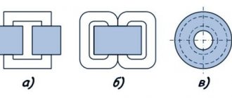
Types of magnetic cores
Magnetic cores are made of rod, armor and ring structures.
Rod type
Vertical cores of stepped cross-section form a circle with horizontal yokes. The windings are located only on the vertical elements. The entire magnetic circuit system is arranged in the form of a closed circuit.
Lamellar magnetic cores
Armor type
The cores have a rectangular cross-section. They occupy a horizontal position. The windings are also made in a rectangular shape. In order to implement such an equipment configuration, a rather complex production technology is required. Therefore, this type of MP is used only in special types of transformers.
Ring – toroidal type
Ring tape magnetic cores are used in the assembly of single-phase power transformers. MPs are made from cold-rolled electrical steel with a thickness of 0.08, 0.3 and 0.35 mm. Toroidal cores are made of ferrite or carbonyl iron. They are widely used in radio electronics.
Ring toroidal MPs
Ferrite grades
Ferrites according to their composition are divided into two groups: manganese-zinc and nickel-zinc. Manganese-zinc ferrites are designated by the letters NM, respectively, nickel-zinc substances are marked by the letters - NN. The number before the letter designation of ferrite means the value of the initial magnetic permeability in units of µinit. This indicator is given with an adjustment to the nominal value. For example, ferrite grade 4000NM has a magnetic permeability with a deviation ranging from – 800 to + 500 µinit.
Magnetic cores are of exceptional importance in the formation of devices such as transformers and other electrical devices. The initial technical characteristics of the devices largely depend on their qualitative composition.