Equipment types
In the operation of high-voltage equipment, reliable insulation between live parts of electrical installations and individual devices is very important. They must also be insulated from the ground. This role, as well as the fastening function of current-carrying parts, is performed by insulators of various types.
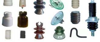
According to the most general classification, that is, from the point of view of the places of their application, they are divided into hardware, station, linear.
The first two types are used in substations, power plants, and current-carrying parts of electrical devices. They are used here as fastenings and insulate switchgear buses (switchgear). According to their functions and location, they can be walk-through or support.
Notes[edit]
- S. L. Kakani (January 1, 2005). Electronics Theory and Applications. New Age International. clause 7. ISBN 978-81-224-1536-0.
- Waygood, Adrian (19 June 2013). Introduction to Electrical Engineering. Routledge. paragraph 41. ISBN 978-1-135-07113-4.
- Klein, N.; Gafni, H. (1966). "Maximum dielectric strength of silicon oxide thin films". IEEE Trans. Electronic devices
.
13
. - Inuishi, Y.; Powers, D.A. (1957). "Electrical breakdown and conduction through Mylar films". J. Appl. Phys
.
58
(9):1017–1022. Bibcode: 1957JAP…. 28.1017I. DOI: 10.1063/1.1722899. - Belkin, A.; and others. (2017). "Recovery of aluminum oxide nanocapacitors after high-voltage breakdown". Scientific reports
.
7
(1): 932. Bibcode: 2017NatSR ... 7..932B. DOI: 10.1038/s41598-017-01007-9. PMC 5430567. PMID 28428625. - "Electrical Porcelain Insulators" (PDF). Product Specification
. Universal Clay Products, Ltd. Retrieved October 19, 2008. - Cotton, H. (1958). Transmission and distribution of electrical energy
. London: English Univ. Click.copied from Insulator Usage, AC Walker Insulator Information page - Holtzhausen, J.P. "High Voltage Insulators" (PDF). IDC Technologies. Archived from the original (PDF) on May 14, 2014. Retrieved October 17, 2008.
- IEC 60137: 2003. “Insulated bushings for a.c. voltages above 1000 V.” IEC, 2003.
- Diesendorf, W. (1974). Insulation Coordination in High Voltage Power Systems
. UK: Butterworth & Co. ISBN. 0-408-70464-0.reprinted on Walker's AC Insulators, Surge and Flashover Information website - Donald G. Fink, H. Wayne Beaty (ed.), Standard Manual for Electrical Engineers, 11th Edition
, McGraw-Hill, 1978, ISBN 0-07-020974-X, pages 14-153, 14-154 - Grigsby, Leonard L. (2001). Handbook of Electrical Power Engineering. USA: CRC Press. ISBN 0-8493-8578-4.
- Jump up
↑ Bakshi, M (2007). Electricity transmission and distribution. Technical publications. ISBN 978-81-8431-271-3. - "Isolators: National Isolators Association Home Page". www.nia.org
. Retrieved December 12, 2022. - Bernhard, Frank; Bernhard, Frank H. (1921). Electromagnetic Yearbook. Electrical engineering pub. Co. p. 822.
- "Understanding IEC Device Insulation Classes: I, II and III". Fidus Power
. July 6, 2022.
More about insulators
Bushing insulators are used to insulate wires running through the walls of buildings. In addition, they carry out the removal of load switch conductors from tanks and switches. These are high-voltage porcelain insulators that have a cavity inside where a metal rod or group of busbars passes.
The so-called bushings are a type of bushing insulation designed for 110 kilovolts and higher voltages. At the bushings, the current conductor is a copper pipe. To make the internal insulation of high-voltage high-frequency bushings, in addition to porcelain, ceramics, bakelite, and other solid organics are used. Insulation can also be liquid or paper-oil.
The so-called “capacitor input” can be organized. This is when layers of special cable paper are placed on a conductive rod, and aluminum foil is laid in thin layers in the middle. Such a structure is necessary so that the potential is evenly distributed along the axis and radially. The capacitor input is usually sealed.
As for support insulators, they support buses, contact nodes of switchgears, and electrical devices. Such devices are either support-pin or support-rod. In the latter, the design is complemented by a porcelain rod with protruding ribs. They are also called wings, they protect from rain.
Conductors
All conductors have electric charges, which, under the influence of potential differences, move towards one of the poles. Positive charges move towards the negative end, and negative charges towards the positive end. This flow is electric current.
Ionic substances and solutions are capable of conducting electricity, but metals provide the maximum conductivity. Copper is often used in wires because it provides excellent conductivity and is inexpensive. But for high conductivity, gold-plated wires are sometimes used.
Each conductor has a power limit (the amount of current it can carry).
Overhead power lines
Now about linear insulators. They secure the wires of overhead lines. They also insulate the outdoor switchgear buses (open switchgear). There are pin and pendant insulators. The first ones received their name because of the peculiarities of their fastening - on metal pins, which are fixed in the traverses of the supporting elements. The devices hold the wires firmly on the supports. Such devices are found on power lines up to a kilovolt. Pin insulators of higher voltages, up to 35 kilovolts, are made as two-element ones.
The flexible connection between wires and supports of power lines with a voltage of 35 kilovolts or more is provided by suspension insulators. Some of them are combined into garlands (plate type). Rod insulators increase the electrical strength of lines, since their breakdown is impossible. The insulating part of the hanging fixtures is made of glass or porcelain. It is connected to the conductive rod and cap by a cement bond.
Special designs have been developed for line insulators. They allow their use in power lines in polluted atmospheres. Such devices have increased discharge rates and also increased creepage distance.
Typical design
First, let's look at an example of a typical design using a sketch of a pin insulator.
Rice. 3. Sectional view of insulator
As you can see in Figure 3, the design includes ribs A and B. Which allow you to increase the electrical strength by lengthening the path for leakage current along the surface. Due to the different slope angles of the ribs, protection from precipitation is possible. So ribs A have a smaller slope, so they are most relevant for solid precipitation - snow, mud, etc. Because moisture can sneak underneath and significantly reduce the discharge voltage.
Unlike them, skirts B allow you to completely eliminate the possibility of moisture ingress in rainy weather. This provides a constant supply of resistance, which guarantees the breakdown voltage. In addition, skirts B are not afraid of ice freezing and can ensure normal operation of high-voltage lines in the event of a difficult meteorological situation.
To fasten the head of the rod, a B thread is provided, which allows you to secure the structure to the console or reinforcing hooks. In the upper part there is a groove G for fixing the wire. Additionally, the wire is tied with wire for more reliable fastening of overhead power lines.
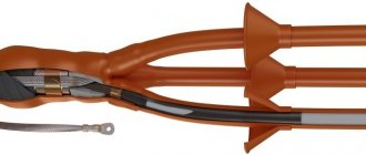
Rice. 4. Bushing design
The bushing insulator has a slightly different design, since its task is not only to isolate the current-carrying busbar from the wall, but also to ensure the normal flow of current inside the insulator itself. Look, the tire is crimped on both sides with an aluminum cap to secure it securely on the outside. Inside, mechanical fastening is carried out using a sealant, which in addition prevents the entry of pollutants and aggressive substances. Also, for the convenience of attaching wires or busbars, an additional petal can be installed on the cover itself, as shown in Figure 4.
A protective shell made of silicone rubber prevents electrical breakdown along the surface from the tire to the flange. Insulation against breakdown of internal elements is carried out using a fiberglass pipe, which is placed inside a ribbed jacket. More detailed information about the parameters can be obtained from the model designation.
Requirements for insulators
Any insulator must satisfy several technical requirements. First of all, a certain electrical strength. It is defined as that electric field strength, expressed in kilovolts per meter, at which the insulating material loses its dielectric properties.
Mechanical strength is also important. It is important to counteract the forces that appear during a short circuit in the circuit between live parts of the equipment.
The insulator must maintain its performance even in all weather conditions, be it snow, hail, or rain. Heat resistance is also an important factor. Temperature changes over a wide range should not affect the electrical properties of the insulator. In addition, it must have a discharge-resistant surface.
Electrophysical and mechanical indicators
These include the nominal value and the breakdown voltage. The latter determines the minimum voltage that causes breakdown of the insulator. The properties of the insulator are characterized by such indicators as discharge and withstand voltage. These parameters have different values if the surface is dry and if it is wet (insulator in the rain).
Thus, there are dry-discharge and wet-discharge values of this voltage, when there is an overlap over the surface while maintaining all the insulating qualities.
Important electrophysical characteristics are the values of 50% pulse discharge voltages of both polarities.
Mechanical indicators are, first of all, the smallest force (load) of destruction, expressed in newtons. It is assumed that it is applied to the insulator cap and directed in a direction perpendicular to its axis. Dimensions and weight also matter.
What are the components of different insulators made of?
The main material for station and equipment insulators was porcelain, which fully meets the above requirements. For casings located inside, as well as components of some types of insulators filled with insulating oil, bakelite, textolite or getinax are more often used.
The so-called “metal fixtures” are metal parts that are fixed to porcelain. It is used to attach the insulator to the base, and to connect current-carrying parts of electrical devices and busbars to the insulator. It is fixed with special cementitious lubricants that have a coefficient of thermal expansion similar to that of porcelain. The insulator body is coated with glaze, which improves its electrical properties.
Classification by location
External installation gives the corresponding insulating devices a greater surface development. It corresponds to a higher microdischarge voltage, which allows insulators of this type of installation to work just as reliably in rain or in a dirty state. This is their main difference from indoor insulators.
By the height of the porcelain part, insulators designed for different voltage ratings can be distinguished from each other. The gradation in the magnitude of mechanical forces for destruction is expressed in changes in diameters.
It happens that one part of the insulator is in open space, while the other is located indoors or in oil. This is exactly the case of the previously described bushings. Often such devices (for example, insulators of transformers, oil circuit breakers) are asymmetrical. It is interesting that the part of the porcelain body that is exposed to air has more developed ribs.
What do the inscriptions on overhead line supports mean?
Surely many have seen the inscriptions on power transmission poles in the form of letters and numbers, but not everyone knows what they mean.
Photo 10. Designations on power line supports.
They mean the following: a capital letter indicates the voltage class, for example T-35 kV, S-110 kV, D-220 kV. The number after the letter indicates the line number, the second number indicates the serial number of the support.
T means 35 kV. 45 is the line number. 105 is the serial number of the support. This method of determining power line voltage by the number of insulators in a garland is not accurate and does not provide a 100% guarantee. Russia is a huge country, therefore, for different operating conditions of power lines (cleanliness of the surrounding air, humidity, etc.), designers calculated different numbers of insulators and used different types of supports. But if you approach the issue comprehensively and determine the voltage according to all the criteria described in the article, then you can quite accurately determine the voltage class. If you are far from the electric power industry, then for a 100% determination of the power line voltage, it is still better for you to contact your local energy company.