03/10/2016 One comment Category: Automation in everyday life, Basics of automation
In everyday life, we often come across switches. These are all kinds of switches, buttons, toggle switches - they allow you to control devices discretely, in other words, turn them on and off. A regular switch consists of two contacts that can be used to close or open an electrical circuit. Discrete control of various devices in automatic mode implies the ability to turn them on and off without human intervention. It is for this purpose that an electromagnetic relay is intended, and that is why not a single automatic control system can do without it.
An electromagnetic relay is a device that has a group of contacts that change their state to the opposite when a control voltage is applied.
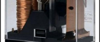
Rice. 1. Electromagnetic relay
In simple words, a relay is a switch that is turned off not manually by a person, but electrically, by applying a control signal. To make it completely clear, let’s consider the principle of operation of an electromagnetic relay.
What is an electromagnetic relay, device, purpose
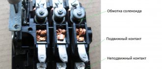
An electromagnetic relay is a switching device that uses an electromagnetic field to operate. It consists of an electromagnetic coil and a movable armature, movable and fixed contacts. The anchor and reel are fixed to the base. The anchor is spring-loaded and positioned so that the fixed contacts have points of contact with the fixed contacts.
Electromagnetic relay device
How does an electromagnetic relay work? When voltage is applied to the winding, an electromagnetic field appears in it. The movably fixed armature is attracted to the coil core, the contacts switch (close/open). This is the job of the relay - to transfer contacts. Different loads are connected to them and, as a result of operation, the circuits through which electric current flows change.
When the power is removed, the electromagnetic field disappears, and the armature returns to its original state under the action of the spring. Accordingly, the circuit returns to its original state. The principle of operation is very similar to the operation of a conventional switch. The only difference is that there is no button and the contacts are “controlled” automatically, and instead of a light bulb there may be a section of a circuit or some kind of device.
Why do you need a relay in electrical circuits?
The figure above shows the simplest circuit with an electromagnetic relay. There is a button that supplies power to the coil. An actuator, for example, an electric lamp, is connected to the contacts. When you press the button, power is supplied to the coil, the armature is attracted to the coil core, and presses on the contacts. They close, voltage is supplied to the light bulb and it lights up. When the power is removed from the coil, the spring pulls the armature to its original position, the power supply circuit to the light bulb is broken and it goes out. This example shows why and how electromagnetic relays are used.
Types of electromagnetic relays
The first classification is based on nutrition. There are electromagnetic relays for direct and alternating current. DC relays can be neutral or polarized. Neutral ones are triggered when power is applied to any polarity, polarized ones react only to positive or negative (depending on the direction of the current).
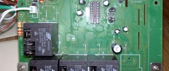
Types of electromagnetic relays by type of supply voltage and appearance of one of the models
According to electrical parameters
Electromagnetic relays are also divided according to sensitivity:
- Trigger power 0.01 W or less - highly sensitive.
- The power consumed by the winding when triggered is from 0.01 W to 0.05 W - sensitive.
- The rest are normal.
First of all, you need to decide on the electrical parameters
The first two groups (highly sensitive and sensitive) can be controlled from microcircuits. They are quite capable of delivering the required voltage level, so that intermediate amplification is not required.
According to the level of switched load there is the following division:
- No more than 120 W AC and 60 W DC - low current.
- 500 W AC and 150 W DC - increased power;
- More than 500 W AC - contactors. Used in power circuits.
There is also a division based on response time. If the contacts close no more than 50 ms (milliseconds) after power is applied to the coil, it is fast acting. If it takes from 50 ms to 150 ms, this is a normal speed, and all those that require more than 150 ms for contacts to operate are slow.
By execution
There are also electromagnetic relays with varying degrees of tightness.
- Open electromagnetic relays . These are the ones with all the parts “in sight”.
- Sealed . They are sealed or welded into a metal or plastic case, inside of which there is air or an inert gas. There is no access to the contacts and coil; only the terminals for supplying power and connecting circuits are accessible.
- Covered . There is a cover, but it is not soldered, but is connected to the body using latches. Sometimes there is a wire loop that holds the lid in place.
The differences in weight and size can be very significant.
And another principle of division is by size. There are microminiature ones - they weigh less than 6 grams, miniature ones - from 6 to 16 grams, small-sized ones weigh from 16 grams to 40 grams, and the rest are normal.
Prices and documentation
Prices
When ordering over 120 pcs, the price is negotiable. When ordering more than 200 pcs. Other forms of execution are also possible.
| Model | retail price | installer/dealer |
| GERCH ZN - regular round | 450 rub. | 349 RUR / 260 RUR |
| GERCH ZN LONG - extended body | 450 rub. | 349 RUR / 260 RUR |
Download
instructions GERCH ZN
| № | Name of instructions | Last date change | Size | |
| 1 | Gerch ZN, Gerch ZN Long - instructions | 10.09.2018 | 1.49 mb | |
| 2 | Gerch ZN - Advertising brochure with abbreviated instructions | 12.07.2018 | 2.19 mb | |
| 3 | Gerch ZN - Connection diagram with Z5R | 05.07.2018 | 0.3 mb | |
| 4 | Gerch ZN - Connection diagram | 08.07.2018 | 0.3 mb |
Types of contact groups
Electromagnetic relays are divided according to the method of contact operation. They can be:
- Normally closed (closed, opening). Abbreviated as NZ, on imported diagrams NC.
- Normally open (open, closing). Designation - BUT on ours - and NO on foreign ones.
- Reversible (switching). Changeover ones differ in appearance, as they have three plates with contacts. They usually only indicate common contact - they write “common” or comon.
In general, the names of the contacts make it clear how they work. Normally closed contacts are initially closed and current flows through them. When the relay is activated, the contacts open and the power circuit is interrupted.
Normally closed (closed) contact: what it means and principle of operation
Normally open (more clearly, normally open) contacts, on the contrary, are open in the normal state. When the relay is activated, the contact closes and current flows through the circuit.
Electromagnetic relay with normally open (open) contact
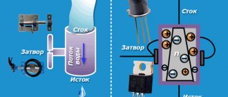
It’s probably already clear how a switching contact works. Unlike the first two, the switch consists of three plates. There are two fixed ones at the edges and a movable one in the center. The moving contact is often called the general contact. In the normal position, the movable plate touches one of the contacts, current flows along this path (in the figure below right).
Operating principle of an electromagnetic relay with switching contacts
When the relay is triggered, the movable contact changes position thanks to the stop frame (in the figure it is just a pin soldered to the movable plate). And the frame is attached to the anchor. After the relay is triggered, a gap appears in the first circuit, and current begins to flow in the second.
These are all types of contacts - it doesn’t seem like there are many. But all three types can be collected in one relay, and the number of groups of each type varies. They are chosen depending on need.
Electromagnetic relays on diagrams: windings, contact groups
The peculiarity of the relay is that it consists of two parts - a winding and contacts. The winding and contacts have different designations. The winding graphically looks like a rectangle, the contacts of different types each have their own designation. It reflects their name/purpose, so identification problems usually do not arise.
Types of electromagnetic relay contacts and their designation in diagrams
Sometimes a type designation is placed next to the graphic image - NC (normally closed) or NO (normally open). But more often the relay affiliation and the number of the contact group are specified, and the type of contact is clear from the graphic image.
In general, you need to look for relay contacts throughout the entire circuit. After all, it is physically located in one place, and its different contacts are part of different circuits. This is shown in the diagrams. The winding is in one place - in the power supply circuit. The contacts are scattered in different places - in the circuits in which they work.
An example of a circuit using electromagnetic relays: the contacts are in the corresponding circuits (see color coding)
For an example, look at the relay diagram. Relays KA, KV1 and KM have one contact group, KV3 - two, KV2 - three. But three is far from the limit. There can be ten, twelve or more contact groups in each relay. And the diagram in the figure is simple. And if it takes up a couple of A2 sheets and there are a lot of elements in it...
Main technical characteristics, pros and cons, scope of application
Like any electrical parts, an electromagnetic relay is selected according to its parameters. First, they decide on the composition of contact groups, then on nutrition. Then it’s time to select characteristics.
- Trigger current or voltage . The lowest current or voltage value at which the contacts switch reliably.
- Release current or voltage . The maximum value of the parameters at which the spring will tear the armature off the coil.
- Sensitivity . The minimum power level at which the relay operates.
- Winding resistance . Measured at +20°C.
- Operating current or voltage . This is the range of values at which the relay will accurately operate under operating conditions.
- Response time . The interval from the moment power is supplied to the winding until the first contact is switched.
- Release time . After what period of time after the power is removed will the anchor “come unstuck”.
- Switching frequency . How many times can a relay operate in a certain period of time?
Characteristics of an electromagnetic relay. One of the types
Electromechanical relays have a long service life and low price. Another plus is the low power drop when switching. But they create interference during operation, contact bounce is possible, the response speed is very low, and there are problems with inductive loads.
All these properties determine the scope of application. Typically this is switching the power supply of devices operating from 220 V AC or 12 V and 24 V DC. Most often, the load is low-power electric motors; lighting and other inductive and active loads are also connected. Switched load power from 1 W to 2-3 kW.
Advantages
Revolutionary technology! Two-wire wired touch button that does not require separate power wires. Thanks to this, it has significant advantages, with ease of installation, like a regular button.
It is unique that the two-wire touch button works without additional power wires, and even with backlighting via the same 2 wires. There have already been positive reviews from installers that an ordinary faulty button can be changed to a touch button in 5 minutes, without even reading the instructions!
Advantages:
- It works fully on 2 wires, which makes it possible to use it to replace mechanical buttons, without laying new wiring.
- Reliably responds to hand touch even through gloves.
- significant work resource. In the harshest conditions, it is guaranteed to work for more than 6 years due to the absence of mechanical wear with each operation, as well.
- original green LED backlight without additional wires.
- high moisture protection - up to 98% humidity.
- operates in a wide temperature range, from -40 to +50 C. Most cheap buttons (based on clock buttons) have a temperature range from -20 to +70 C, although many manufacturers try to keep silent about the lower value (-20). This significantly reduces their already extremely low work resource.
- high load characteristics, from 1 A and above (depending on the modification), which allows you to use the button without a controller, switching the electromechanical lock directly.
- uniform, LED panoramic or ring illumination of green color
For comparison, in products based on tact buttons, the maximum load current is about 0.05A! If it is exceeded, the response life of a conventional button is significantly reduced.
How to test an electromagnetic relay
The performance of an electromagnetic relay depends on the coil. Therefore, first of all, we check the winding. They call her a multimeter. The winding resistance can be either 20-40 Ohms or several kOhms. When measuring, simply select the appropriate range. If there is data on what the resistance value should be, we compare. Otherwise, we are content with the fact that there is no short circuit or break (the resistance tends to infinity).
You can check the electromagnetic relay using a tester/multimeter
The second point is whether the contacts switch or not and how well the contact pads fit. This is a little more difficult to verify. A power source can be connected to the output of one of the contacts. For example, a simple battery. When the relay is triggered, the potential must appear on the other contact or disappear. This depends on the type of contact group being tested. You can also monitor the presence of power using a multimeter, but it will need to be switched to the appropriate mode (voltage control is easier).
If you don't have a multimeter
You don't always have a multimeter at hand, but you almost always have batteries. Let's look at an example. There is some kind of relay in a sealed housing. If you know or have found its type, you can look at the characteristics by name. If the data is not found or there is no relay name, look at the body. Usually all important information is indicated here. The supply voltage and switched currents/voltages are required.
Checking the electromagnetic relay winding
In this case, we have a relay that operates from 12 V DC. It’s good if there is such a power source, then we’ll use it. If not, we assemble several batteries (sequentially, that is, one after another) in order to obtain the required voltage in total.
When batteries are connected in series, their voltage is summed up
Having received a power source of the required rating, we connect it to the coil terminals. How to determine where the coil terminals are? Usually they are signed. In any case, there are symbols “+” and “-” for connecting constant power sources and signs for an alternating type such as “≈”. We supply power to the corresponding contacts. What's happening? If the relay coil is working, a click is heard - this is the anchor being pulled. When the voltage is removed it is heard again.
Checking contacts
But clicks are one thing. This means that the coil is working, but you still need to check the contacts. Perhaps they have oxidized, the circuit closes, but the voltage drops significantly. Maybe they have worn out and the contact is poor, or maybe, on the contrary, they have boiled and do not open. In general, to fully test the electromagnetic relay, it is also necessary to check the functionality of the contact groups.
The easiest way to explain is using a relay with one group as an example. They are usually found in cars. Car enthusiasts call them by the number of pins: 4 pins or 5 pins. In both cases there is only one group. Simply, a four-contact relay contains a normally closed or normally open contact, and a five-contact relay contains a switching group (changeover contacts).
Electromagnetic relay 4 and 5 pins: contact location, connection diagram
As you can see, power is supplied in any case to the pins labeled 85 and 86. And the load is connected to the rest. To test a 4-pin relay, you can assemble a simple combination of a small light bulb and a battery of the required rating. Screw the ends of this bundle to the contact terminals. In a 4-pin relay these are pins 30 and 87. What happens? If the contact is closed (normally open), when the relay is activated, the light should light up. If the group opens (normally closed) it should go out.
In the case of a 5-pin relay, the circuit will be a little more complicated. Here you will need two bundles of a light bulb and a battery. Use lamps of different formats, colors, or somehow separate them. If there is no power to the coil, you should have one light on. When a relay is activated, it goes out and another one lights up.
Description
A two-wire touch normally open button with increased mechanical resistance is intended for use in access control systems and other low-current electronic systems that require a button that creates a short circuit when pressed.
Can be connected to a controller, electromechanical lock or electromagnetic lock via a relay.
Can be used in places with high and very high traffic. GERCH ZN - Touch exit button (door open)
| Options | meaning |
| Button type | normally open |
| Closing time, sec. | 3 or via controller |
| Application | electromagnetic or electromechanical lock controller, multi-apartment intercoms, electromechanical locks, electromagnetic locks (via relay) |
| Backlight | panoramic green LED backlight |
| Sound signal | No |
| Light signal | During the circuit the backlight does not light up |
| Current consumption in standby mode, A | 0,001 |
| Maximum current consumption, A | 0,001 |
| Maximum throughput, A | 1,5 |
| Operating voltage, V | from 3 to 20 constant voltage |
| Frame | ABS plastic with compound |
| Case color | metallic silver, metallic bronze, metallic green, black, white, grey, yellow, orange, blue |
| type of instalation | invoice |
| Operating temperature, C | from -40 to +50 |
| Maximum humidity | 98% |
| GERCH ZN | |
| Dimensions, mm | 41*41*10 |
| Distance between the center of mounting holes, mm | 31 |
| GERCH ZN LONG | |
| Dimensions, mm | 77*29*11 |
| Distance between the center of mounting holes, mm | 50 |