4.6
Average rating: 4.6
Total ratings received: 150.
4.6
Average rating: 4.6
Total ratings received: 150.
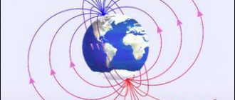
A magnetic field is a force field that acts on moving particles that have an electrical charge. For clarity, the magnetic field is depicted in the form of magnetic lines or magnetic induction lines. What kind of lines do these lines have, where do they begin and where do they end - read the answers to these questions below.
Magnetic field sources
The above experiment clearly demonstrates how anyone can determine the direction of the Earth's magnetic field lines. The arrow of the device will show the directions to the south and north poles. The longitudinal axis of this indicator will coincide with vector (B).
Electromagnetic field of a conductor
If a similar experiment is performed near a current-carrying conductor, the circular location of the power lines can be determined by the movement of the arrow. They form closed rings perpendicular to the center line of the cable.
Electromagnetic induction
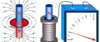
A fairly strong field is generated by the induction coil. A practical example is the solenoid of a relay or shut-off device. When turned on, such a unit pulls the metal core inside.
A schematic drawing explains the direction of the retracting force that is generated in the central axis of the solenoid
Vortex field
A careful study of the magnetic field using magnetic induction lines allows us to establish a very important feature of it. Magnetic induction lines have neither beginning nor end. They are always closed.
Let us remember that with an electrostatic field the situation is different. Electrostatic field strength lines begin at positive charges and end at negative charges.
Fields with closed lines of force are called vortex fields. The magnetic field is a vortex field.
The closure of magnetic induction lines is a fundamental property of a magnetic field. It lies in the fact that the magnetic field has no sources. No magnetic charges similar to electric ones were detected.
Note that neither the laws of electrodynamics nor any other known physical laws prohibit the existence of magnetic charges; more precisely, the existence of particles with magnetic charges. Therefore, searches for such particles have been and are being undertaken. However, they have not yet been successful. The reason for this is not yet clear.
What is electromagnetic induction
Magnetic induction vector: formula
This phenomenon is accompanied by the appearance of a field in a certain environment, a current in a conductive material, or the polarization of individual objects. Electromagnetic induction depends on the change in magnetic parameters over time or the corresponding movement of functional components.
The exact date of this discovery has been established - 08/29/1831. The author is known - M. Faraday. The scientist revealed the proportional dependence of the EMF in a closed loop on the speed at which the magnetic flux changes.
Vortex field
Fields with closed vector lines are called vortex fields. The magnetic field is a vortex field.
The closure of magnetic induction lines is a fundamental property of a magnetic field. It lies in the fact that the magnetic field has no sources. Magnetic charges similar to electric ones do not exist in nature.
The magnetic field is a vortex field; at each point in the field, the magnetic induction vector has a certain direction. This direction is indicated by a magnetic needle or can be determined by the gimlet rule. The magnetic field has no sources; magnetic charges do not exist in nature.
Questions for the paragraph
1. How are a closed loop with current and a magnetic needle oriented in a uniform magnetic field?
2. What are magnetic induction lines called?
3. What fields are called vortex fields?
4. How does a vortex field differ from a potential field?
Lenz and Faraday's laws
The phenomenon of electromagnetic induction
Faraday's law shows the mathematical relationship of the most important parameters of this phenomenon:
E = - dФ/dt,
Where:
- E – EMF;
- Ф – flux formed by a magnetic induction vector penetrating through a limited contour;
- t – time.
In this expression, “-” before the main part denotes the rule formulated by E. Lenz. This Russian scientist found that the current in the circuit under consideration creates a field direction opposite to the force component of the magnetic flux.
For practical application, it is more convenient to express the above-mentioned patterns as follows:
E = -N*(dФв/dt).
This example shows an induction coil placed in a magnetic (alternating) field. Additional components:
- N – number of solenoid turns;
- Fv – flow through a single turn.
In the differential representation, this law is described by the integral over an arbitrary surface of the magnetic induction vector, which permeates an area with certain boundaries. This form allows you to take into account only field changes. Magnetic flux is a set of lines that pass through a certain area. To simplify calculations, it is assumed that the field is uniform.
What is the induced emf?
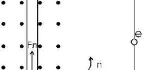
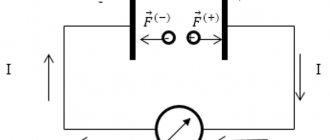
To determine the magnitude of the resulting EMF, consider a circuit placed in a uniform magnetic field with induction B; a conductor of length l can move freely along this circuit.
Under the influence of force F, the conductor begins to move with speed v. In some time ∆t the conductor will travel the path db. Thus, the work expended on moving the conductor will be
Since the conductor consists of charged particles - electrons and protons, they also move along with the conductor. As is known, a moving charged particle is acted upon by the Lorentz force, which is perpendicular to the direction of motion of the particle and to the magnetic induction vector B, that is, electrons begin to move along the conductor, leading to the emergence of an electric current in it.
However, a conductor with current in a magnetic field is subject to a certain force Ft, which, in accordance with the left-hand rule, will be opposite to the action of the force F, due to which the conductor moves. Since the conductor moves uniformly, that is, at a constant speed, the forces Ft and F are equal in absolute value
where B is the magnetic field induction,
I is the current strength in the conductor arising from the action of induced emf,
l is the length of the conductor.
Since the path db traversed by the conductor depends on the speed v and time t, the work spent on moving the conductor in the magnetic field will be
When a conductor moves in a magnetic field, almost all the mechanical energy expended on this work is converted into electrical energy, that is
Thus, transforming the last expression, we obtain the value of the induced emf when a straight conductor moves in a magnetic field
where B is the magnetic field induction,
l – conductor length,
v is the speed of movement of the conductor.
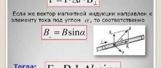
This expression corresponds to the movement of the conductor perpendicular to the lines of magnetic induction. If movement occurs at a certain angle to the lines of magnetic induction, then the expression takes the form
In practice, it is quite difficult to calculate the speed of movement of the conductor, so we transform the expression to the following form
where dS is the area that the conductor crosses during its movement,
dΦ – magnetic flux penetrating the area dS.
Thus, the induced emf is equal to the rate of change of the magnetic flux that penetrates the circuit.
To indicate the direction of current movement in the circuit, a “–” sign is introduced, which indicates that the current in the circuit is directed against the positive bypass of the circuit. Thus
Often a circuit consisting of many turns of wire moves in a magnetic field, so the induced emf will have the form
where w is the number of turns in the circuit,
dΨ = wdΦ – elementary flux linkage.
To paraphrase the previous definition, the induced emf in a circuit is equal to the rate of change in the flux linkage of this circuit.
Right hand rule for magnetic and electric forces
Induction EMF formula
If a conductor moves in a constant magnetic field, a movement of charged particles is generated in it. Calculations and experiments are not needed to clarify the basic parameters of the phenomenon. It is enough to remember the simple technology shown in the following figure.
Right hand rule
With this arrangement of the permanent magnet, the conductor is moved from bottom to top in the direction where the raised thumb is pointing. The palm is turned towards the North Pole. Four closed fingers will show the direction of movement of the induction current.
How does induced emf and induced current occur?
As I said in previous articles, an electromagnetic field arises around a conductor through which electric current flows. I reviewed this magnetic field here and here. However, there is also the opposite phenomenon, which is called electromagnetic induction. This phenomenon was discovered by the English physicist M. Faraday.
To consider this phenomenon, consider the following figure
This figure shows a frame made of a conductor placed in an electric field with induction B. If this frame is moved up and down in the direction of the magnetic lines of force or left and right perpendicular to the lines of force, then the magnetic flux Φ penetrating the frame will be almost constant. If you rotate the frame around the O axis, then over a certain period of time ∆t the magnetic flux will change by a certain amount ∆Φ and as a result, an induced emf Ei will appear in the frame and a current I, called the induced current, will flow.
Information about magnetic induction lines
From the data presented, the force nature of the field created by alternating current or the movement of a conductor is clear. A vector expression is used to accurately express the effects on the indicator element. At the beginning of publication, such a component was the compass needle. The following shows the possibility of using a conducting frame with current.
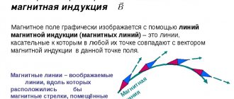
Magnetic field lines are used to visually depict this phenomenon. If at any point of such a curve you draw a vector (B) along a tangent, it will indicate the direction of influence. Size to scale shows a certain strength.
By simply checking the geometric parameters, you can establish the uniqueness of each vector. They, like the lines of the force field, do not intersect. Below are methods for clarifying the distribution of energy flows in the conductor and the surrounding space.
Two ways to determine the direction of a force field (electric current)
For the version with a straight conductor, the right hand is squeezed as shown in the first figure. The thumb is directed in the direction of current flow. Clenched fingers will show the direction of the lines of force. The second part of the picture demonstrates the determination of field parameters when passing current through a ring frame - the “gimlet rule”. The rotation of this tool is similar to the direction of the current.
For your information. If the solenoid is long enough, the field will be uniform over most of the working volume. It is acceptable to assume that the magnetic field lines in this case are located parallel.
What is magnetic flux?
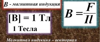
Magnetic flux is a physical quantity proportional to the number of magnetic field lines in a certain area of space. Since lines of force are an abstract concept, therefore, magnetic flux characterizes the intensity of the magnetic field, that is, magnetic induction in a given area. Magnetic flux is denoted by Ф and has the dimension Wb (Weber).
Thus, the magnetic flux can be expressed by the following expression
where B is magnetic induction,
S – surface area for which the magnetic flux is calculated.
The figure shows magnetic field lines that are perpendicular to surface S, that is, the angle between the magnetic induction vector B and surface S is 90°. However, it often happens that it is necessary to calculate the magnetic flux on a plane not perpendicular to the magnetic induction vector. To determine such a magnetic flux, it is necessary to bring the magnetic induction vector to the normal
Thus, the final expression for finding the magnetic flux will have the form
where B is the magnetic induction vector,
S is the surface area on which the magnetic flux is found,
α is the angle between the magnetic induction vector and the normal to the surface S.
Image of magnetic induction lines
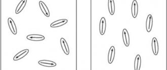
To visually study the distribution of the field in space, the dimensions of the measuring elements are reduced. Iron filings evenly scattered on the surface of a cardboard sheet or other electrically neutral plane are suitable for the experiment.
Magnetic induction lines - a visual representation of the force field distribution
If you bring a magnet from the reverse side, metal particles, like miniature compass needles, are distributed along the force strips. By the distance between them one can judge the energy parameters of the field in a certain place. Create a drawing in the same way. Greater density (near the poles) indicates an increased value of induction.
For your information. Physically separating a permanent magnet into parts will not create separate poles. This is a fundamental difference from electrostatic charges of a certain polarity, which also create a force field.
The presented knowledge is used to solve various engineering problems. In particular, simple rules for determining the direction of current in a conductor and the direction in which the solenoid core moves are useful.
Magnetic levitation train accelerates to high speeds with minimal energy losses
A little history of magnetism
The study of the phenomenon of magnetism began many centuries ago, when back in the 6th century. BC. In ancient China, stones (rock) were discovered that attracted iron objects. In 1269, the French explorer Peter Peregrin placed small steel needles on the surface of a permanent spherical magnet and saw that they were not located chaotically, but along certain lines that intersected at two points, called “poles” by analogy with the geographic poles of the Earth. We can say that this was the first “visualization” of magnetic lines.
Only in 1845, the English physicist Michael Faraday formulated the concept of a “magnetic field” to understand the essence of magnetic phenomena. He believed that both electrical and magnetic interactions are carried out through invisible fields - electric and magnetic. The magnetic field is continuous in space and is capable of acting on moving charges.
In 1831, Michael Faraday discovered that an alternating magnetic field generates an electric field, and vice versa - a non-constant (time-varying) electric field creates a magnetic field. This phenomenon became known as Faraday's law of electromagnetic induction. The word induction is of Latin origin (induction) meaning “guidance, removal.”
What is self-induced emf? Inductance
As you know, there is a magnetic field around a conductor carrying current. Since the magnetic field induction is proportional to the current flowing through the conductor, and the magnetic flux is proportional to the magnetic induction, therefore, the magnetic flux is proportional to the current flowing through the conductor.
Thus, when the current changes, the magnetic flux (or flux linkage) changes. However, in accordance with the law of electromagnetic induction, a change in flux linkage leads to the appearance of an induced emf in the conductor.
This phenomenon (the appearance of an emf) in a conductor when the current passing through it changes is called self-induction. The EMF arising due to self-induction is called self-induction EMF EL, which is equal to
where dΨL is the change in flux linkage.
Therefore, between the electric current in the conductor and the flux linkage of the magnetic field arising around the conductor, there is a certain proportionality coefficient connecting them. This coefficient is inductance - denoted L (it has the old name self-inductance coefficient)
The amount of inductance characterizes the ability of an electrical circuit to create flux linkage (magnetic flux) when electric current flows through it. The unit of inductance is Henry (denoted Hn)
Thus, inductance depends on the geometric dimensions of the current-carrying conductor and on the magnetic properties of the magnetic circuit through which the magnetic flux created by the current-carrying conductor is closed.
In the next article I will tell you how to calculate the inductance of current-carrying conductors of different shapes.
Notes
- If we take into account the effect of the electric field E
, then the formula for the (total) Lorentz force takes the form: F→=qE→+qv→×B→.{\displaystyle {\vec {F}}=q{\vec {E}}+q.}In the absence of an electric field (or if the term describing its action is specifically subtracted from the total force), we have the formula given in the main text.
- This definition, from a modern point of view, is less fundamental than the one given above (and is simply a consequence of it), however, from the point of view of proximity to one of the practical ways of measuring magnetic induction, it can be useful; also from a historical point of view.
- That is, in the most fundamental and easiest to understand form.
- That is, in the particular case of constant currents and constant electric and magnetic fields, or - approximately - if the changes are so slow that they can be neglected.
- It is a special magnetostatic case of the Ampere-Maxwell law (see later in the article).