An electromagnetic relay (EMR) is an electromechanical device that responds to changes in a system parameter by opening or closing contacts, the main task of which is to perform switching operations in electrical circuits. Triggering can be carried out under the influence of factors such as electric current, pressure or liquid level, or light energy.
Main areas of application in automation systems
In most cases, EMR is used for switching loads at a switching current of 10–16 A in alternating (220 V) or direct (5–24 V) current networks. Such technical characteristics allow the relay to be used to protect such electrical installations as low-power motors, heaters, electromagnets, and other consumers with a power of up to 4 kW. In addition, relays are used to control circuits
- instrumentation and automation;
- alarm systems;
- industrial automation;
- remote control systems.
EMRs are especially effective when working with low-voltage inductive loads with a short time constant (up to 10 ms). At the same time, current overloads during startup are small, and when the equipment is turned off, voltage surges do not occur. The ability of the device to switch complex loads is ensured by its configuration with contact groups designed for the appropriate currents.
Design
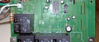
The main element of solid-state relays is an electronic board consisting of three main elements:
- A control unit that provides stable voltage levels, which at the input ranges from 70 to 220 Volts.
- Interchange unit , consisting of elements that send and receive a light signal. A transparent dielectric is located between the transmitting and receiving elements.
- Power keys:
- for direct current - based on transistors.
- for variable - on base
triacs or thyristors.
Relay internals.
The device must be mounted after the load, followed by grounding, to prevent short circuits.
Advantages and disadvantages of using EMR
The main arguments in favor of using an electromagnetic relay in an electrical circuit control circuit are:
- resistance to the effects of surge voltages on networks;
- the ability of electrical insulation to withstand up to 5 kV between the contacts and the control coil;
- slight voltage drop across the contacts in the closed state;
- the ability to switch loads up to 4 kW with a size of less than 10 cm³;
- low heat dissipation rates;
- the presence of galvanic isolation between the contact group and control circuits;
- relatively affordable price.
Among the “disadvantages” of such a technical solution, it is worth highlighting the limited mechanical life of the equipment, high current consumption, and the creation of interference at the moment of operation.
Short circuit protection
Short circuits can occur when the insulation in the electrical circuit is damaged, external influences or network overload.
To protect against short circuits, fast-acting fuses designed specifically for solid-state relays are used. Such devices are capable of breaking the circuit much faster than breakdown of the input element.
The most important indicator of fuses is the speed of operation.
The rated current values of fuse links are indicated by the manufacturer in the technical documentation. They must be higher than the maximum currents of the protected devices.
After tripping, the fuses must be replaced.
Design and principle of operation
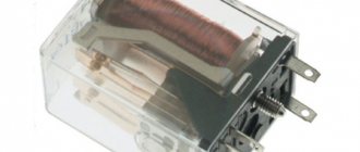
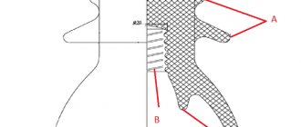
The basis of the EMR design is a core made of a non-magnetic alloy with an electric coil made of copper wire coated with a dielectric (varnish, synthetic or fabric insulation). When voltage is applied to the input, the moving element is retracted, due to which the contacts move.
The design also provides for the presence of several functional blocks:
- intermediate elements that ensure operation of the actuator;
- control components that convert electrical energy at the input into a magnetic field);
- actuators (contacts) acting directly on control circuits.
EMRs are produced with normally closed, open contacts, and devices of mixed design.
The operating principle of an electromagnetic relay is based on the operation of a magnetic field, the lines of force of which penetrate the core when electric current is supplied to the coil. As a result, an armature with magnetic properties is attracted to the core. As a result, the contact group opens or closes. When the voltage drops, the return spring returns the moving element to its original state.
A design feature of intermediate EMRs is the presence of a semiconductor time attachment in the device. It is controlled by turning the resistor. To reduce inertial performance, the device can be equipped with a laminated core.
Main types of EMR
EMR relays are usually classified according to several parameters. Based on the design features, contact and non-contact devices are divided. In the first case, we are talking about devices that, when triggered, act with a contact group on the power circuit, providing a connection or break in it. In the second, a similar result is achieved by changing one of the parameters (voltage, current, capacitance, resistance).
Depending on the method of connection, equipment is divided into the following types.
- Primary (the device is connected directly to the control circuit).
- Secondary, requiring connection to the network through a measuring current transformer.
- Intermediate, operating from the executive bodies of other relay devices. This principle of operation allows for signal multiplication or amplification.
Depending on the type of input voltage, DC and AC devices are produced. The first option, in turn, can be divided into polarized and neutral. Its key difference is the sensitivity of the device to the polarity of the power source (depending on this, the armature changes the direction of movement of the armature).
Among the disadvantages of DC equipment are the relatively high cost and the need for use in conjunction with a power supply. Such problems do not arise when operating an AC EMR, but their significant “minus” will be vibration during operation and reduced sensitivity.
Current relay
The current relay is designed to monitor this parameter in electrical consumer circuits. It is possible to connect the device to power circuits or using an instrument transformer. Data transfer to other circuits is carried out by connecting a resistor.
The main design difference of a current relay is the design of the coil. It uses a thick conductor, which has low resistance and is wound on the core with a small number of turns. To control the specified parameters, an automated on/off system is provided.
Time relay
In most cases, time relays are installed when it is necessary to form start-up cascades when connecting high-power equipment. This approach allows you to avoid sudden load surges when the equipment is turned on, exceeding the permissible values. The time delay is provided by an additional short-circuited circuit, the role of which is played by a copper sleeve placed on the core.
The operating principle of a time relay is based on the “quenching” of the electromagnetic field strength due to the presence of oppositely directed current. As a result, a delay is formed, the value of which can be 0.07–0.15 s. The adjustment is performed by the EMR armature spring. The same effect is observed when turning off the power, but the delay may be 0.5–2 s.
Popular models
The most popular models include the following series of solid-state relays:
- SSR-40 DAH is a powerful, inexpensive 1-phase relay manufactured by FOTEK;
- HTH-6044.ZD3, 60A, 3-32V DC - solid-state relay designed to control single-phase loads up to 60A;
- HD-1044.ZA2 10A, 90-250V AC—single-phase solid-state relay manufactured by KIPPRIBOR for AC control signals;
- MD-1544.ZD3 15A, 3-32V DC - 1-phase relay in a reduced-size housing, designed to control single-phase loads up to 15A;
- G3PA 24-240V AC/DC is a three-phase relay manufactured by OMRON, output voltage from 24 to 480V.
Example of designation: SSR – 40 DAH stands for:
- SSR stands for single-phase model, (TTR stands for three-phase);
- 40 - load in Amperes;
- D - input signal at direct current, corresponding to 3-32 V; (V - resistance at alternating current 80-250 V);
- A - input voltage on alternating current (D - on direct current).
- N - output voltage range corresponding to 90-480 V.
Connection features: typical diagrams
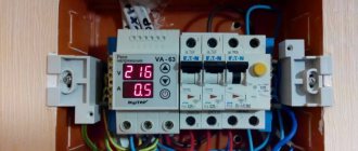
The most common scheme is to connect a single-phase load through relay contacts or a magnetic starter to protect drive mechanisms from voltage fluctuations that occur during emergency situations. Its use allows the possibility of adjusting the operating parameters of the system in a fairly wide range. For example, you can set the optimal turn-on delay.
Typical connection diagram via relay contacts
In the diagram shown in the figure, the 220 V relay is connected directly to the controlled network. This allows the device to measure the input voltage and determine its compliance with acceptable parameters. If the value falls within the specified range, automatic reclosure is activated (automatic restart). With a set time interval, the contacts are closed and connected to the network.
Circuit with magnetic starter
The connection of a single-phase load can be carried out according to a scheme that provides for the control of switching operations through magnetic starters. The main difference in its operation is the fact that initially the MP is turned on/off, which in turn connects or disconnects the load. The device is selected in accordance with the characteristics of the connected equipment.
Intermediate relay connection diagram
When using an intermediate electromagnetic relay in a circuit, its configuration depends on the nature of the connected loads. In most cases, the device functions as a contactor, which effectively distributes power between load elements.
In this case, the neutral is connected directly to the coil contact. The supply phase wire is connected through the “Stop” button, which is triggered by opening. Its second contact also joins the system phase. Normally closed contacts are used to connect the load, and normally open contacts of the intermediate EMR are used for the phase.
To ensure continuous power supply to the coil, one of the output contacts is connected to the load. The contact group is closed. To disconnect the load and EMR, the electrical circuit is broken using the “Stop” button. A magnetic starter can be additionally included in the circuit to control a high-power load. To control the relay, a thermostat, light sensors, and motion sensors can be used.
Electromagnetic relays on diagrams: windings, contact groups
The peculiarity of the relay is that it consists of two parts - a winding and contacts. The winding and contacts have different designations. The winding graphically looks like a rectangle, the contacts of different types each have their own designation. It reflects their name/purpose, so identification problems usually do not arise.
Types of electromagnetic relay contacts and their designation in diagrams
Sometimes a type designation is placed next to the graphic image - NC (normally closed) or NO (normally open). But more often the relay affiliation and the number of the contact group are specified, and the type of contact is clear from the graphic image.
In general, you need to look for relay contacts throughout the entire circuit. After all, it is physically located in one place, and its different contacts are part of different circuits. This is shown in the diagrams. The winding is in one place - in the power supply circuit. The contacts are scattered in different places - in the circuits in which they work.
An example of a circuit using electromagnetic relays: the contacts are in the corresponding circuits (see color coding)
For an example, look at the relay diagram. Relays KA, KV1 and KM have one contact group, KV3 - two, KV2 - three. But three is far from the limit. There can be ten, twelve or more contact groups in each relay. And the diagram in the figure is simple. And if it takes up a couple of A2 sheets and there are a lot of elements in it...
First time check
After installing a new device or a repaired EMR (after rewinding its coils), it is necessary to check the equipment. The full range of work includes the following operations.
- External inspection, internal diagnostics and maintenance (cleaning, integrity of seals, condition of seals, leads).
- Checking the contact group and mechanism. If defects are detected, they are adjusted.
- Testing of EMR for compliance of actual technical characteristics with nominal parameters when the relay is activated, returned, held.
- Checking the electrical strength of insulation.
- Checking the delay time when triggering or returning.
- Testing the system under reduced voltage conditions.
EMR adjustment
The measurement method may differ significantly depending on the type of relay. When making adjustments, it is important to consider the following principles.
- Weakening the return spring leads to an increase in return time and a decrease in response voltage.
- If you increase the initial gap between the core and the armature, the operating speed will increase and the voltage will be higher. The same effect is observed when adjusting the end gap in relation to the return speed and voltage.
- With an increase in the number of make/break contacts and a simultaneous increase in spring pressure, the voltage and speed of return and operation increase, respectively.
It must be taken into account that any changes directly affect the operation of the contact system. Therefore, when adjusting the parameters of the EMR, it is necessary to select a position in which the return spring will be maximally tensioned, and the gap can provide the greatest armature stroke.
Basic parameters for choosing a relay
contact Group
One of the key parameters for choosing an EMR is the configuration of its contacts: the mechanism most often operates to open, close or switch. When choosing, you must consider the following parameters:
- voltage drop;
- rated load at which switching is performed with high reliability;
- maximum permissible switched power, voltage and current;
- mechanical and electrical resistance to wear;
- pulse current;
- minimum load;
- contact material.
Specifications
The basis for choosing a 220 V electromagnetic relay is:
- operating voltage and current;
- sensitivity (the minimum value of power supplied to the winding at which the device is able to switch);
- actuation, release, vibration times of contacts;
- return coefficient, which for EMR of different types ranges from 0.1 to 0.98;
- operating current (its minimum value at which switching, closing or opening of contacts occurs);
- safety factor (from 1.4 to 2);
- relay switching frequency.
Operating principle
To understand the operating principle of solid-state relays, you need to know their design features.
The interaction of the controlled and control signal is ensured by galvanic or optical isolation.
One of the main elements of the SSR is an opto-isolator, or optocoupler in the form of an LED and a photosensitive device that isolates the input from the output.
When electricity passes through the LED connected to the input section of the solid state relay, it lights up. Focusing through the gap, the light is transmitted to a photosensitive transistor or semistor.
The principle of operation of the device is to close and open contacts that transmit voltage.
The circuitry of all solid-state devices is approximately the same. Minor differences between different models do not affect its functionality at all.
The mechanism works by closing and opening the contact terminals that transmit voltage.
Operation of EMR, frequent equipment malfunctions
A relay is a device with a limited mechanical life: during its operation it periodically burns out, the contacts wear out, and carbon deposits form on their surface. That is why cleaning is required during routine maintenance of the EMR. In addition, it is worth considering that equipment of any type is designed for a certain number of operations. This is due to the fact that under the influence of sparks and the electric arc that is formed during switching, gradual destruction of the metal occurs.
The most common problems that arise during the operation of a relay are a break in the coil wire or the occurrence of an interturn short circuit in it. Signs of such a malfunction may be a loud hum of the EMR or failure when turned on. Externally, local overheating and interturn short circuits may be indicated by darkening on the coil. A cracking sound from the relay may indicate contact wear.
When the circuit is turned off, the EMR may remain in the active state, in which case the contacts “stick” occurs. To check the technical condition of the coil, use a multimeter or a continuity tester. If the circuit is closed, there is no break. When voltage is applied to the winding, the contact group should operate, and the circuit resistance should be zero. As part of scheduled maintenance, equipment is cleaned from dust and dirt.