A signal is any variable containing some type of information. Moreover, this information can be transmitted over a distance, transferred to storage devices, displayed on the screen and through speakers, or perform similar actions with it. Existing analog and digital are radically different in the nature of their origin, method of transmission and storage.
Analog signal
This natural type of signals surrounds us everywhere and constantly. Sound, image, tactile sensations, smell, taste and brain commands. All signals that arise in the Universe without human participation are analog.
In electronics, electrical engineering and communication systems, analog data transmission has been used since the invention of electricity. A characteristic feature is the continuity and smoothness of parameter changes. Graphically, an analog communication session can be described as a continuous curve corresponding to the magnitude of electrical voltage at a certain point in time. The line changes smoothly, breaks occur only when the connection is broken. In nature and electronics, analog data is generated and distributed continuously. No continuous signal means silence or a black screen.
In continuous communication systems, the analogue of sound, image and any other data is electrical or electromagnetic pulses. For example, the volume and timbre of a voice is transmitted from a microphone to a speaker via an electrical signal. Volume depends on the magnitude, and timbre on the frequency of the voltage. Therefore, during voice communication, first voltage becomes an analogue of sound, and then sound becomes an analogue of voltage. In the same way, any data is transmitted in analog communication systems.
What is a discrete signal
In a digital data storage and transmission system, the absence of a signal is also a form of information exchange. At some point in time it is equal to zero, at another it takes on some value. Therefore, a discontinuous signal is called discrete, hence the name discretus or divided. Analog data is broken down into separate blocks, processed and transmitted as digital code.
Discreteness does not imply a break in communication. Digital systems widely use a binary system for processing and exchanging information. Binary means encoding data using ones and zeros. In a fraction of a second, the signal intermittently takes on the value 1 or 0. Instead of a continuous curve, we have individual discrete values. A certain set of zeros and ones already carries some information. A primitive set is a bit or binary digit. By itself it doesn't mean anything. Data can only be encoded by combining eight bits into the next most complex combination - a byte. The more bytes combined, the more and more accurately the transmitted information can be described.
The quality of the generated data is affected not only by the number of combined bits, but also by the transmission speed. A continuous analog waveform must be broken down into as many more mini discontinuous signal sections. The resulting sound and color will match the original. A high-quality discrete signal forms an exact copy of an analog signal. For example, an MP3 audio track encoded at 320,000 bits per second (320 kbps) is significantly better than one encoded at 128 kbps. Tracks with a speed less than 128 are generally impossible to listen to.
Chips ISO1211/12
ISO1211/12 is a specialized integrated circuit for implementing discrete inputs with individual galvanic isolation. Using the ISO121x , it is possible to build discrete inputs that comply with the IEC 61131-2 standard and types 1, 2 and 3 described previously. It is possible to connect external sensors with a maximum operating voltage of up to 24 V to such inputs (Figure 8).
Rice. 8. Implementation of discrete input based on ISO1211 digital isolator
ISO121x isolators provide a simple solution with low power consumption and precise current limitation. These isolators do not require a power supply on the primary side and operate over a wide range of supply voltages from 2.25 to 5.5 V. ISO121x have inputs that are tolerant to ±60 V and have reverse polarity protection, which is important in case of faults with significant reverse voltages and currents. Digital isolators in this family support data rates up to 4 Mbps with a 150 ns pulse transmission guarantee. ISO1211 is suitable for channel separation in multi-channel systems, while ISO1212 is suitable for solutions where space is limited. The block diagram of one channel is shown in Figure 9.
Rice. 9. ISO1211/12 channel block diagram
The isolators accept 24V discrete input signals and provide an isolated discrete output. The external resistor Rmeas sets the value of the inflow current limitation. The voltage threshold at which switching between levels occurs is set by resistor Rthr. To transmit discrete signals across the isolation barrier, the ISO121x family of chips use ON-OFF keying (OOK) amplitude keying. The ISO1211EVM evaluation kit (Figure 10) and the ISO1212EVM 8-channel isolated discrete input board (Figure 11) from Texas Instruments are available to evaluate the capabilities of digital isolators.
Fig. 10. ISO1211EVM Evaluation Kit
Rice. 11. ISO1212EVM 8-channel digital signal receiver evaluation module
The main parameters of ISO1211 and ISO1212 digital isolators are shown in Table 1.
Table 1. Parameters of ISO1211/12 digital isolators
| Name | ISO1211 | ISO1212 |
| Limit current range, mA | 2,2…7,3 | |
| Built-in isolation power converter | No | |
| Number of channels | 1 | 2 |
| Number of forward/reverse channels | 1/0 | 2/0 |
| Insulation voltage, V | 2500 | |
| Peak insulation voltage for 1 s, V | 3600 | |
| Maximum pulse insulation voltage with a pulse shape of 1.2/50 μs, V | 4000 | |
| Data transfer rate, Mbit/s | 4 | |
| Signal delay, typical, ns | 140 | |
| Maximum operating frequency, MHz | 2 | |
| Default state | No | |
| Supply voltage range, V | 2,25…5,5 | |
| Operating temperature range, °C | -40…125 | |
| Frame | 8SOIC | 16SSOP |
The ISO121x family of digital isolators offer faster operating speeds and faster response times than traditional optocoupler solutions (standard optocouplers have response times of tens of microseconds), as well as smaller overall dimensions and low power loss (Figure 12). Additionally, when implementing discrete outputs based on ISO121x, there is no need for an additional Schmitt trigger buffer, simplifying system design. Ultimately, we can say that ISO1211/12 chips are a more preferable solution for implementing discrete input decoupling than traditional optocouplers.
Rice. 12. Comparison of operating temperatures: traditional solution +84.1, ISO1212 +44.9
What is the difference between a continuous signal and a discrete one?
At first glance, the differences in the signals may not be distinguishable. Both are transmitted as electrical impulses through wires or as electromagnetic waves in the ether. Converted into sound and image, displayed on speakers and screen. But the difference is significant. The difference between an analog signal and a digital signal is due to the peculiarities of data processing and transmission.
Analog data is not encoded or encrypted, it is simply mapped into electrical or electromagnetic pulses. The receiver converts the pulses in full accordance with the received signal. The transmitted and received impulse is multifaceted and is characterized by a constant smooth change over time. Magnitude and frequency determine the parameters of the information. An example would be matching a certain screen color to a given voltage. Over time, the colors change smoothly following the change in voltage.
It would seem that the natural origin, ease of generation, transmission and reception favor the use of an analog signal. But electrical and electromagnetic interference comes into play. This can be electromagnetic interference from electrical networks, operating mechanisms, terrain, thunderstorms, solar storms, noise generated by the operation of transmitting and receiving equipment, and others. They change a smooth curve. The information arrives at the receiver with changes. Hissing, wheezing and distorted images are common in analog communications.
Digital technology uses a completely different transmission principle. Analog data is first encoded and only then transmitted. Coding consists of describing a continuous curve of analog information. At any given moment in time, the transmitted pulse has the value of one or zero, and a certain sequence of bits reflects the entirety of the original picture or sound.
A discrete signal is like Morse code, but instead of dots and dashes there are clear bits. Nothing more, noise and interference do not bother them. The main thing for digital information is to reach the goal. Numbers without impurities will transmit data and be transformed into sound and color without changes. But a weak signal may not convey the full picture. As an example, words or images disappear completely. Therefore, cellular transmitters are installed as close to each other as possible, and repeaters are also used.
An example of continuous and discrete signals would be old wired and new cellular communications. Through old PBXs it was sometimes impossible to talk to the neighboring house. Noise and poor signal amplification made it difficult to hear each other. To have a full-fledged conversation, you had to shout loudly yourself and listen to your interlocutor. Cellular communications based on digital technology are another matter. The sound is encoded and is transmitted well over long distances. You can clearly hear your interlocutor even from another continent.
Both types of communication are not without their drawbacks, and the key differences are:
- Analog is prone to interference and arrives with distortion. While digital comes completely without distortion or is absent at all.
- Any receiver of this principle can receive or intercept analogue broadcasts. A discrete transmission is addressed to a specific recipient, is encrypted and is less accessible to interception.
- The volume of transmitted data in analog communication is finite, so it has practically exhausted its usefulness in transmitting a body signal. On the contrary, with the development of technology for converting analog information into digital code, the volume and quality of broadcasting is growing. For example, the main difference between digital and analog television is the excellent image quality.
Digital technology wins in all respects. The debate is only among music lovers. Many music lovers and sound engineers claim that they can distinguish between an analog original and a digital copy. However, most listeners are unable to do this. And with the development of digital systems, analog data is encoded more accurately. The original sound and the digital copy become almost indistinguishable.
How an analog signal is converted to digital and vice versa
The first to convert mathematical, physical and computer information into digital form. It was not difficult to describe the formulas and calculations. But to transform analog reality into digital arrays, special devices were already required. They became analog-to-digital converters, or ADCs for short. They are designed to convert various physical quantities into digital codes. The reverse action is performed by DAC devices.
Any digital transmitters and receivers are equipped with such converters. For example, for a cell phone, the incoming sound must be processed and transmitted in digitized form. At the same time, it is necessary to receive a code from the other subscriber, convert it and transmit the voltage to the speaker. The same goes for images on smartphones and TVs. In any case, the initial information is voltage.
There are many types of ADCs, but the most common are the following:
- parallel conversion;
- successive approximation;
- delta-sigma, with charge balancing.
Conversions in ADCs are conceptually related to measurement and comparison. Encoding is the process of comparing data received from a source with a standard. That is, the resulting analog value is compared with the reference value (with a given voltage). The standard is information about a specific color, sound, etc. It corresponds to the ideas about the converted signal embedded in the device. The reference quantity data is then encoded for transmission. During analog-to-digital processing, no physical signal transformations occur. A digital matrix (model) is made from analog.
In a simplified way, the operation of any ADC can be represented as follows:
- Measurement of voltage amplitude at certain time intervals.
- Comparison with the standard and generation of data.
- Uploading digitized information about amplitude changes to the transmitter.
The quality of transmitted information depends on two parameters - accuracy and frequency of measurements. The more accurately the incoming voltage is measured and encrypted, the higher the quality of the transmitted information. Therefore, it matters a lot how many bits the converter can encrypt. The denser the information flow, the more accurate the data transfer. This is expressed in the colors of the screen, the contrast of the picture and the purity of the sound. The next important indicator is sampling, that is, the frequency of measurements. The more often, the less measurement failures and the need for smoothing. Overall, the more frequently and accurately a converter can measure and process the resulting voltage, the better it is.
Answer
1. Discreteness. You can only perform a step after completing the previous one. For example, in the algorithm for calculating 8 * 3 + 2 (without parentheses), you first perform the multiplication (according to the rule), and only then add 2. Otherwise, the answer is incorrect.
2. Certainty. You cannot divide 8 by 3 if you are clearly told: multiply. Certainty is a clear statement of the conditions of the task.
3.Efficiency. After completing the actions, you will receive the answer 26 and only 26. Effectiveness follows from certainty. Thanks to the effectiveness, you will receive an “environment” in which all objects are uniquely defined.
4. Clarity. (Need some explanation here too? In my opinion, the property speaks for itself.)
5. Mass scale. The algorithm can be applied more than once. That is, in our example 8*3+2 there are operations of multiplication and addition, but they can occur not only in our example, but are “suitable” for many other tasks in which multiplication or addition is required.
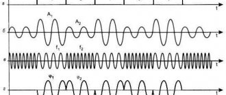
What do the spectra of an analog and discrete signal look like?
The image of signals can be represented as two functions. The figure clearly shows how a continuous signal differs from a discrete signal. The source voltage changes smoothly, while the processed voltage changes intermittently. The discrete spectrum periodically coincides stepwise with the continuous spectrum.
Discrete changes occur abruptly, after a certain period of time. The level in a digital system is encrypted and any voltage value is described in binary code. The smoothness of the transformation and the originality of the transmitted data depend on the frequency of measurements. The more accurately the signal level is described and the more often the measurement is carried out and processed, the more accurately the spectrum of the initial and transmitted signals matches.
Dynamic range
Dynamic range
An important characteristic of any dynamic measurement system is its dynamic range. There is no clear definition of this parameter for a signal yet, so it is generally accepted that this is the ratio of its largest and smallest values measured by the system in a certain period of time.
For each stream, it is important that its dynamic range matches as closely as possible the similar characteristics of the system or device designed to convert, transmit and store its values. The correct selection determines how accurately the information of any stream will be transmitted and converted.
Which communication systems use a digital signal and which analog?
Despite its archaic nature, analogue technology is still used for telephone and radio communications. Many wired networks are still analog. These are mainly traditional telephone lines of local operators. But digital channels are already widely used for backbone data transmission. Analogue technology is also used in simple and cheap portable radio stations.
All newly created systems use digital signal processing technology. These are fiber optic and wire lines, signaling and telemetry, military and civil industrial communications. And of course, television is switching to digital broadcasting. The analogue method of data transmission has exhausted itself. It has been replaced by a new high-quality and secure connection.
List of books to help you understand analog and digital signals
You can study and compare the principles of data processing and transmission in more detail by reading the following literature:
- Sato Yu. Signal processing. First meeting. / Per. from Japanese; edited by Yoshifumi Amemiya. - M: Publishing House "Dodeka-XXI", 2002. The book provides the basic knowledge about DSP methods. Addressed to radio amateurs, students and schoolchildren just starting to study data transmission systems.
- Introduction to digital filtering / ed. R. Bogner and A. Konstantinidis; translation from English - M: Publishing House "Mir", 1977. This book provides popular and accessible information about various data processing systems. Analogue and digital systems are compared, the pros and cons are described.
- Fundamentals of digital signal processing: Course of lectures /Authors: A.I. Solonina, D.A. Ulakhovich, S.M. Arbuzov, E.B. Soloviev, I.I. Hook. - St. Petersburg: Publishing house "BHV-Petersburg", 2005. The book was written according to a course of lectures for students of the State University of Technology named after. Bonch-Bruevich. The theoretical foundations of data processing are outlined, discrete and digital systems of various conversion methods are described. Intended for study in universities and advanced training of specialists.
- Sergienko A.B. Digital signal processing (second edition) - St. Petersburg: Publishing house "Piter", 2006. Electronic educational and methodological complex for the discipline "Digital signal processing". A course of lectures, a laboratory workshop and methodological recommendations for independent work are presented. Designed for teachers and self-study for undergraduate students.
- Lyons R. Digital signal processing. 2nd ed. Per. from English – M.: Binom-Press LLC, 2006. The book provides detailed information about DSP. Written in clear language and with plenty of illustrations. One of the simplest and most understandable books in Russian.
The good old analogue connection is quickly losing ground. Despite modernization and improvements, the ability to share data has reached its limit. In addition, old diseases remain - distortion and noise. At the same time, digital communications are free of these shortcomings and transmit large amounts of information quickly, efficiently, and without errors.
Example
Let's take the Smart Home system controller EasyHomePLC 5.2 as an example.
It has 32 discrete inputs. The input voltage must be from +9 to +60 volts for the controller to consider it as one.
Of these 32 inputs, 16 can be analog. The input signal is from 0 to 10 volts.
18 discrete outputs. Of these, 9 are relay (switching 16 amperes 230 volts), 9 are open collectors for connecting external relays.
6 PWM outputs with switching current up to 1.4 amperes and voltage up to 30 volts per output. This is control of an LED strip, or a 0-10 volt signal if you connect an RC circuit to the PWM output (a resistor and capacitor will smooth out the PWM signal).
It has many communication interfaces: Ethernet, two RS-485, two RS-232, miniUSB (for firmware).
You can read more about inputs and outputs here:
Once again about the inputs and outputs of the controller
260, total, today
Related posts:
- Cable installation for a Smart Home As I already wrote, the most unreasonable way to save money in construction...
- Presence sensors in a smart home Article updated in October 2021. Many thoughts added, updated...
- Once again about controller inputs and outputs My article about PLC inputs and outputs is one of...
- Smart House on a central controller (PLC) A small educational program about building a Smart House system on a central controller...
- Smart Home on PLC: lighting control Let's consider classic light control without any smart home: Three options...
- Smart House on PLC: climate control The heating control function combines the control of the following systems: Radiator heating (passive…
- Access control on ARIES PLC and EasyHome Description of the task The task was as follows: the apartment has an entrance door…