Main technical characteristics by which insulators are selected
According to current standards, the selection of electrical insulators is carried out according to the following technical characteristics:
- dry-discharge voltage - this parameter determines at what number of volts it is possible to close the insulating element with the supporting structure, provided the surfaces are dry;
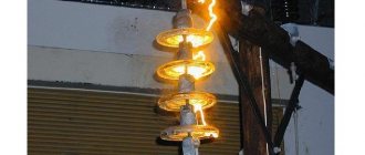
- wet discharge voltage - a characteristic similar in value, but in a situation where the surfaces are moistened by rain (at an angle of inclination of the jets up to 45 degrees); in this situation, resistance to electric current is reduced to a minimum - from 9.5 to 10.5 kOhm cm; this characteristic is always inferior to the dry discharge;
- breakdown voltage - the number of volts at which a discharge will occur between the poles; depending on the structural device, the poles can be a rod and cap or a busbar and a flange;
- mechanical strength - the ability to withstand bending, tearing or shearing of the head; these indicators are determined by securing the insulator and applying the appropriate load until the material is completely destroyed;
- thermal stability - the ability to maintain properties during alternating heating and cooling to certain temperatures, then applying voltage with multiple discharges;
Of the batch of insulators produced at the plant, only 0.5% of the products are tested. All manufactured elements are checked by applying an overlapping voltage for three minutes, with the formation of spark discharges.
Also read: Technical characteristics of the cable – ShVVP
Design
Structurally, all electrical insulators differ in the methods of attachment to the supporting structure and cable fastening. The main task of this product is to prevent electrical discharges; for this purpose, they are made in the form of plates or rods with ribs. These ribs are needed so that the discharge develops at an angle to the field lines. In the figure below you see examples of typical products of different shapes and designs:
Classification
Reliable operation of electrical installations and networks is possible provided that insulating elements of appropriate design and characteristics are used. There are several principles by which insulators are classified.
By voltage
Depending on the rated voltage, insulating elements are divided into 14 classes according to the value of this characteristic in lines or electrical installations from 1 to 1,150 kW.
By purpose
Taking into account the purpose, insulating elements can be:
- stationary - involve mechanical fastening of current-carrying rods and busbars for electrical installations; These insulators can be support insulators, performing a load-bearing function for placing busbars in cells, and pass-through insulators - if current-carrying lines pass through walls or other elements of building structures;
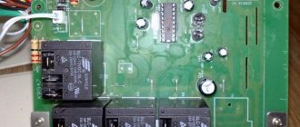
- hardware (white in the photo) – similar in purpose to stationary ones, but used as part of various equipment; for example, such parts are used for rectifier units, power devices, complex substations and other electrical installations;
- linear - provide for the use of external high-voltage lines as insulating elements or for busbars of switchgears.
This type of classification determines the features of the use of insulators.
By material
The insulator body can be made of the following materials:
- porcelain - withstands significant mechanical loads during compression, but is not designed for dynamic impact; the strength of the product is further increased by covering the outside surface with glaze to prevent the penetration of moisture, dust and dirt into the surface layer;
- polymers – structures with elastic deformation and a monolithic structure are used; the specific strength of the polymer material significantly exceeds the similar characteristics of porcelain cases; the disadvantage is destruction under the influence of ultraviolet radiation, therefore such insulators are used indoors and in installations;
- glass - inferior in strength to other varieties, chips are possible upon impact; but they are resistant to aggressive environments, lighter in weight, easier to care for and maintain, compared to porcelain products.
Also read: Technical characteristics of the cable - AVBbShv
Each material has its own pros and cons, which affects the nature of its use.
By mounting method
Depending on the method of fastening, insulators are:
- pin(s) – fixed to a metal axis;
- hanging (b) - in the form of plate-shaped elements assembled in a garland; the number of individual parts depends on the required voltage class;
- rod (c) – a solid rod that performs a supporting function or is suspended from a mounting bracket.
Each of the listed types has its own design structure.
Other principles of classification
Also, taking into account operating conditions, insulators are distinguished into external, used in the open air, and internal, installed indoors or in electrical installations.
Polymer insulators
Support linear rod organosilicon insulators OLSK-6-10, OLSK-12.5-10, OLSK-16-20, OLSK-12.5-35 are designed for fastening and insulating uninsulated and insulated wires of type SIP-3 (SAX), ELV and PZVG on intermediate, intermediate-corner and other supports of overhead power lines and switchgear of power plants and alternating current substations with a voltage of 6-35 kV with a frequency of up to 100 Hz at an ambient temperature from - 60° to + 50°C. The wire can be fixed in a groove or on the neck of the insulator. Fastening to metal structures of supports (traverses) is carried out using a bolted connection M20, M24. The design of modification “A” insulators allows for rolling out SIP-3, PZV and PZVG wires directly onto the insulators without the use of rolling rollers. This reduces installation time and reduces its cost. After rolling the wires over modification “A” insulators, they must be secured in the groove or on the neck of the insulator on straight sections of the line and on the neck when the line turns. Manufactured: - OLSK 6(12.5)-10 according to TU 3494-005-82442590-2008; — OLSC 16(12.5)-20(35) according to TU 3494-005-82442590-2009.
Advantages of support linear insulators over pin insulators:
- reduced cost of traverses;
- reduced costs for transportation of traverses;
- installation labor intensity has been reduced, 100% factory readiness for installation on a traverse with one nut;
- impenetrability under any form of stress;
- the reliability of the insulating unit has been increased, the weakest elements (pins, caps) have been excluded from the design;
- use of spiral bundles for fastening wires, unified with pin insulators.
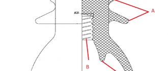
Support linear rod organosilicon insulators OLSK 6-10, OLSK 12.5-10, OLSK 16-20, OLSK 12.5-35 are a solid insulating ribbed body made of porcelain or a combination of composite materials, reinforced in the lower part with a steel flange. The fundamental difference between rod insulators and pin insulators is their “impenetrability” under all types of electrical influences, since the thickness of the solid insulation between the wire and the grounded flange is commensurate with the lengths of the discharge path through the air and over the surface, and its electrical strength is disproportionately higher than the strength of the air gap. Such an insulator can be blocked during lightning overvoltages on an overhead line, but not pierced, as often happens with pin insulators. The insulating body of rod insulators carries not only the electrical load, but also completely determines the mechanical strength of the insulating unit. The developed surface of the insulators ensures moisture-discharge characteristics of the insulators that exceed the requirements of the PUE for areas of permissible degree of pollution.
Explanation of the symbol for support linear rod organosilicon insulator:
| OLSC | — Support Linear Rod Organosilicon |
| 6; 12,5 | — Normalized breaking force for bending, kN |
| 10;20;35 | — Rated voltage, kV |
| A; B | — Modification index of the insulator head |
| 2; 4 | — Modification index of the insulating part of the insulator |
| Type | Rice. No. | Rated voltage, kV | Normalized breaking force for bending, kN | Normalized mechanical tensile strength, kN | Construction height Н, mm | Insulation height L, mm | Creepage distance, mm | Withstand voltage, kV | Discharge voltage 50 Hz in dirty and wet state, kV | Specific surface conductivity of the contamination layer, µS | Permissible degree of pollution according to PUE | Weight, kg | ||
| full thunderstorm impulse | 50 Hz dry | 50 Hz in the rain | ||||||||||||
| OLSK 6-10-A(B)-2 | 1 | 10 | 6,0 | 4,0 | 213 | 160 | 290 | 120 | 80 | 45 | 13 | 10 | 2 | 1,5 |
| OLSK 6-10-A(B)-4 | 2 | 410 | 30 | 4 | 1,6 | |||||||||
| OLSK 12.5-10-A(B)-2 | 3 | 12,5 | 10,0 | 155 | 280 | 10 | 2 | 1,9 | ||||||
| OLSK 12.5-10-A(B)-4 | 4 | 400 | 30 | 4 | 2,0 | |||||||||
| OLSK 16-20-A(B)-4 | 5 | 20 | 16,0 | 12,0 | 340 | 280 | 780 | 150 | 90 | 60 | 26 | 30 | 4 | 3,3 |
| OLSK 12.5-35A(B)-2 | 5 | 35 | 12,5 | 10,0 | 400 | 340 | 960 | 210 | 165 | 120 | 42 | 10 | 2 | 4 |
Maintenance and operation of insulators
Insulators are selected according to design and characteristics, taking into account operating conditions. During application, these elements of overhead lines or electrical installations are inspected along with other equipment.
The frequency of inspections is determined depending on the characteristics of the elements. The check is carried out at least once every six months if we are talking about external power lines. Insulating elements in installations can be checked less frequently, during the scheduled inspection periods of the units.
If the power line passes through places of heavy pollution or critical areas (industrial areas, residential areas, etc.), the frequency of inspections is reduced to once a quarter.
During the inspection, it is necessary to ensure the integrity of the insulators, the reliability of fastening, and clean the parts from dust and dirt. Defective elements are replaced with intact ones. The inspection is carried out during a power outage.
Electrical insulators are irreplaceable elements of power lines and electrical equipment. But for their reliable operation, proper selection and compliance with current standards during inspection and maintenance are required.
4.2. Reliability requirements
4.2.1. The reliability of an insulator is determined by the average annual failure rate, the probability of failure-free operation and the gamma-percentage service life.
A failure in normal operating mode is considered to be the destruction of an insulator or a decrease in its electrical parameters, leading to flashover at operating voltage.
The average annual failure rate is selected from the following range: 0.000005, 0.00001, 0.00005, 0.0001.
The normalized value of the average annual failure rate must be indicated in the technical specifications for a specific type of insulator.
Probability of failure-free operation P
calculated by the formula
P
(
t
) = 1 —
At
, (1)
where t
— time since the start of operation, year;
A
— average annual failure rate, 1/year.
4.2.2. The gamma-percentage service life of insulators with a probability of 0.999 should be at least 30 years.
4.3. Requirements for the components of insulators
4.3.1. Insulator terminations must comply with the requirements of GOST 12393 and GOST 27396.
4.3.2. The outer and inner surfaces of the ends must be hot-dip galvanized.
The coating must comply with the requirements of GOST 9.307. The thickness of the coating is at least 70 microns.
To obtain the specified size, it is allowed to perform mechanical processing of the internal thread after applying the coating.
4.3.3. The threads of the ends of the retaining insulators must comply with GOST 6357 and be preserved with lubricant in accordance with GOST 1033.
4.6. Package
Packaging of insulators - type S/KU-1, combination of inner packaging with transport containers - TE-0, 1, 3, K/VU-0 in accordance with GOST 23216 for transportation conditions and permissible shelf life specified in section 8.
Boxes for insulators must meet the requirements of GOST 2991.
The weight of boxes with packed insulators is no more than 110 kg.
Polymer materials used for the manufacture of the protective shell of the insulating part of insulators must be classified as PV-0 in terms of combustion resistance according to GOST 28157.
6.2. Acceptance tests
6.2.1. Acceptance tests are carried out according to the indicators, in the sequence and volume specified in tables 4 and 5.
Table 4
| Indicator name | Item number | Sample size | |
| Technical requirements | Test methods | ||
| 1. Surface quality of the insulating part | 4.1.2 | 7.2 | 100 % |
| 2. Mechanical tensile test force for 1 min | 4.1.4 | ||
| 3. Deviations from nominal dimensions and weight | 3.5 | According to table 5 | |
| 4. Destructive mechanical tensile force | 4.1.3 | 7.3 | |
| 5 Quality of zinc coating | 4.3.2 | 7.5 | |
Table 5
In pieces
| Lot size N | Sample size |
| Up to 100 incl. | 3 |
| From 101 to 500 incl. | 5 |
| Over 500 | |
| Note - If the calculation does not yield an integer, then select the next integer. | |
6.2.2. Tests according to points 1, 2 of Table 4 are carried out according to a continuous control plan.
Insulators that do not meet one of the indicators are rejected.
6.2.3. Tests according to points 3-5 of Table 4 are carried out according to a sampling plan. During random control, the sample is completed using the random selection method in accordance with GOST 18321.
Upon receipt of satisfactory test results on all insulators of the first sample, the batch is accepted.
If unsatisfactory test results are obtained on two or more insulators of the first sample, the batch is rejected.
If unsatisfactory test results are obtained on one insulator of the first sample, repeated tests are carried out on a double sample of insulators selected from the same batch. Upon receipt of satisfactory test results on all insulators of the second sample, the batch is accepted.
If unsatisfactory test results are obtained on one insulator of the second sample, the batch is rejected.